Publisher’s version / Version de l'éditeur:
Vous avez des questions? Nous pouvons vous aider. Pour communiquer directement avec un auteur, consultez la première page de la revue dans laquelle son article a été publié afin de trouver ses coordonnées. Si vous n’arrivez pas à les repérer, communiquez avec nous à [email protected].
Questions? Contact the NRC Publications Archive team at
[email protected]. If you wish to email the authors directly, please see the first page of the publication for their contact information.
https://publications-cnrc.canada.ca/fra/droits
L’accès à ce site Web et l’utilisation de son contenu sont assujettis aux conditions présentées dans le site LISEZ CES CONDITIONS ATTENTIVEMENT AVANT D’UTILISER CE SITE WEB.
Paper (National Research Council of Canada. Institute for Research in Construction), 1989
READ THESE TERMS AND CONDITIONS CAREFULLY BEFORE USING THIS WEBSITE. https://nrc-publications.canada.ca/eng/copyright
NRC Publications Archive Record / Notice des Archives des publications du CNRC :
https://nrc-publications.canada.ca/eng/view/object/?id=80ea6fc8-8fe1-4466-917b-17dfa49c3788 https://publications-cnrc.canada.ca/fra/voir/objet/?id=80ea6fc8-8fe1-4466-917b-17dfa49c3788
NRC Publications Archive
Archives des publications du CNRC
This publication could be one of several versions: author’s original, accepted manuscript or the publisher’s version. / La version de cette publication peut être l’une des suivantes : la version prépublication de l’auteur, la version acceptée du manuscrit ou la version de l’éditeur.
For the publisher’s version, please access the DOI link below./ Pour consulter la version de l’éditeur, utilisez le lien DOI ci-dessous.
https://doi.org/10.4224/40001425
Access and use of this website and the material on it are subject to the Terms and Conditions set forth at
Sprinklers in combustible concealed spaces
Lougheed, G. D.; Richardson, J. K.
Ser
TH1
N a t b a l
Research Om8eil nathtdN 2 1 d derecherdretcancrda
no. 1605
c. 2 Institute for lnstitut de B L N . I Research in recherche en
Construction construction
Sprinklers in Combustible Concealed
Spaces
by
G.D. Lougheed and J.K. Richardson.
,.. ..
.r-.71Reprinted from
Journal of Fire Protection Engineering Vol. 1, No. 2, Apr./May/June 1989 p. 49-62
(IRC Paper No. 1605)
La norme
NFPA-
13,
Norme pour l'installation des systhmes d'extincteurs automatiquesB
eau, exige que tous les vides dissimulds de construction combustible soient protdgds par des extincteurs automatiques
B
eau, sauf dans certains cas. L'une de ces exceptions s'applique aux ensembles combustiblesB
solives de bois lorsque la membrane de plafond estB
moins de 6 po (152 mrn) des solives. Deux essais ont dt6 effectu6s pour analyser la propagation du feu dans un plafond de ce type. Une protection par extincteurs automatiquesB
eau a kt6 pdvue pour les essais afin de ddterminer son efficacitdB
limiter la propagation du feu dans les vides pour lesquels cette protection n'est pas obligatoire en vertu de l'exception.Les essais effectuCs indiquent que les vides dissimulCs de
6 po (152 mrn)
non protbges entre . la membrane de plafond et les solives constituent une voie majeure de propagation du feu dans tout le bbtiment. L'omission d'extincteurs dans ces vides ne doitStre
envisagee que si l'aire de ces vides est limitde par des coupe-feu ou si d'autres moyens sont prbws pour emficher que le feu ne se propage. Ces essais ont aussi d6montd que les extincteurs automatiquesB
eau ont une efficacitd limit&.J. of Fire Prot. E n g ~ , i
(Z),
1989, PP 49-62Sprinklers in Combustible Concealed Spaces
G.D. Lougheed and
J.K.
RichardsonFire Research Section
Institute for Research in Construction National Research Council Canada
Ottawa, Ontario
SUMMARY
NFPA 13
-
Standard for the Installation of Sprinkler Systems requires that all combustible concealed spaces be protected with sprinklers, with certain exceptions. One exception is for combustible wood joist assemblies where the ceiling membrane is within 6 inches (152 mm) of the joists. Two tests were carried out to .examine fire spread in such an assembly. Automatic sprinkler protection was included in the tests to determine its effec- tiveness in containing fire spread in spaces permitted to be unsprinklered by the excep- tion.The present tests indicate that unsprinklered 6 inches (152 mm) concealed spaces
between the ceiling membrane and joists represent a major path for fire spread through- out a building. Omitting sprinklers in such a space should only be considered if such spaces are limited in areal extent by fire stopping or some other means is used for limit- ing fire spread. These tests also show that sprinkler protection has limited effectiveness
Concealed spaces in buildings are an inevitable aspect of some types of construction with crawl spaces created by construction of floors over uneven ground, dropped ceilings installed to conceal piping or ductwork, or ceilings lowered i n rooms modified to suit changing needs. Whatever the reason for their presence, com- bustible concealed spaces create special prob- lems for those concerned with fire protection in buildings. A fire established in a concealed space containing combustibles may be complete- ly out of reach of hose streams and other fire fighting efforts and can thereby spread to other parts of the building. If the fire subsequently emerges in several sprinklered areas, many sprinklers may be activated and the water supply may be over-taxed. As a result, even buildings equipped with automatic sprinklers may be lost if a fire becomes established in an unsprinklered combustible concealed space.
There has been long standing recognition of the need to sprinkler concealed spaces. The National Fire Protection Association Standard on the Installation of Sprinkler Systems, NFPA-13,l requires in Subsection 4-4.4 that all combustible concealed spaces be protected by sprinklers. It has been recognized, however, that sprinkler
installation is not always practical, and several exceptions have been incorporated into the stan- dard to eliminate the need to make an "experi- enced judgement" each time a situation is encoun- tered. Most of these exceptions appear to have been incorporated in NFPA 13 on the basis of their reasonableness in the context of specific sit- uations. Unfortunately, the specific conditions that justified the exception may not be present in all the situations to which it is applied.
Prior to 1985, the Standard permitted sprinklers
to be omitted fiom combustible concealed spaces formed between a ceiling and the joists above if the ceiling membrane was attached directly to the underside of the joists. An exception was added in 1985 to include concealed spaces creat- ed by suspending a ceiling membrane within 6
in. (152 mm) of the underside of combustible wood joists. This exception was included in recog- nition of the difficulty of installing sprinklers in
spaces less than 6 in. (152 mm) deep
-
a recogni- tion that had been traditionally extended to pitched roof spaces a t the eaves. The exception does not require the installation of fire stopping or other fire protection.Laughed & Richardson, Sprinklers in Combustible Concealed Spaces
/'-
;omst Soace N u m b e r s S t e e i Bsa- 7
2 4 2 3 22. 21 20 14 i 9 :? :5 :5 : c i 3 !2 :! 10 9 8 7 6 5 4 3 2 I
Table 1. Material and Equipment Specifications
S p r r k ! ? + S y i t e i S t e e i Bean Item Joists Floor Ceiling Test 1 Test 2 Sprinklers Wood S t u d W a ~ l Specifications
2 in x 1 0 in x 24 ft (50.8 mm x 254 mm x 8.7 m) spruce with 9% moisture
content.
5/8 in. (16 mm) waferboard with flame spread rating# of 232.
1/4 in (6 mm) plywood with a flame spread rating# of 211 mounted in an alu- minum T-bar assembly with 4 ft x 4 ft (1.2 m x 1.2 m) spacing.
3/8 in. (9.5 mm) gypsum board with a flame spread rating# of 17 on the Con- cealed space side of the ceiling assembly, and mounted in an aluminum T-bar assembly with 4 ft x 4 ft (1.2 m x 1.2 m) and 2 ft x 4 ft (0.6 m x 1.2 m) spac- ings.
165°F (74°C) Grinnell Duraspeed upright sprinklers with a 1/2 in. (12.5 mm) orifice on a light hazard "above and below" wet pipe schedule (no sprinklers were mounted below the ceiling assembly).
_/ 24 23 22 21 20 I 9 I 8 I 7 16 I5 : 4 13 12 11 10 T h e r n o c o u p l e i o c a t 8 o n s
'
~ r 0 ~ a n e 5 Bu:ner3'
@J S p r , n k l e r L o c a t o n s & S p r , n k i e r V a l v e @ P r e s s u r e Gauge# The flame spread ratings were measured using the standard tunnel test. Samples were tested On the side which was exposed to the concealed space.
Space Numbers
Figure 1. Plan view of the ceiling assembly showing the location of the propane burner, sprinklers and thermocouples for Test 1.
J. of Fire Prot. E n g ~ , i (2), 1989, pp 49-62
nature of fire spread in a concealed space creat- ed by a ceiling assembly suspended 6 in. (152 mm) below the wood joists. The space was pro- tected by sprinklers even though not required by NFPA 13. The automatic sprinkler protection was included in order to determine its effective- ness in containing fire spread in the confined space produced when the ceiling is suspended within the limits permitted by the Standard.
Test Facility
A 24 R long by 32 R wide (7.3 m x 9.8 m) ceiling assembly was constructed with nominal 2 in. by 10
in. (51 mm by 254 mrn) spruce joists spaced 16 in. (406 mm) on centres and a 518 in. (16 mm) thick waferboard subfloor. An aluminum T-bar ceiling was suspended below the joists using wires with a
6 in. (152 mm) space created between the bottom of the joists and the top of the ceiling panels. The specifications for the materials used in the test assembly are given in Table 1.
The plan view of the assembly used for the test is shown in Figure 1. The relative positions of the sprinklers and the thermocouples are also indicated. The joists a t the south end- of the assembly were supported by a gypsumboard on wood stud wall which enclosed that end of the joist spaces. The remaining three sides of the concealed space between the joists and the ceil- ing were open. The joists were also supported along the center and the open (north) side of the assembly by 6 in. (152 mm) deep steel beams
mounted on concrete block columns.
The sprinkler piping layout and relative sprin- kler locations are shown in Figures 1,2 and 3. A light hazard "above and below" pipe schedule (no sprinklers were installed below the ceiling) was used with a 130 ft2 (12.1 m2) spacing in the concealed space using Grinnell Duraspeed upright sprinklers on a wet system. The sprin- kler deflectors were located 1 in. (25 mm) below the bottom of the joist.
Ignition
Source
Ignition was provided through a 1 R x 3.5
ft
(0.3 m x 1.1 m) opening in the ceiling membrane by a 3.4 x 10⁵ B t u h r (100 kW) propane sand burner with dimensions of 6 in. x 30 in. (150 mm x 760 mm). This source approximates the3.1 x 105 Btuthr (90 kW) ignition source intensi- ty used in the Steiner tunnel test.2 The top of the burner was located 28.5 in. (720 mm) below the bottom surface of the waferboard flooring with the flame just able to reach that surface a t full propane flow. The burner was centered on a joist space with some overlap into the two a@a-
cent spaces. The location of the ignition source relative to the sprinklers for the first test is shown in Figure 1 and in Figure 9 for the second test.
Instrumentation
Temperatures were measured using 26 gauge
I !
k
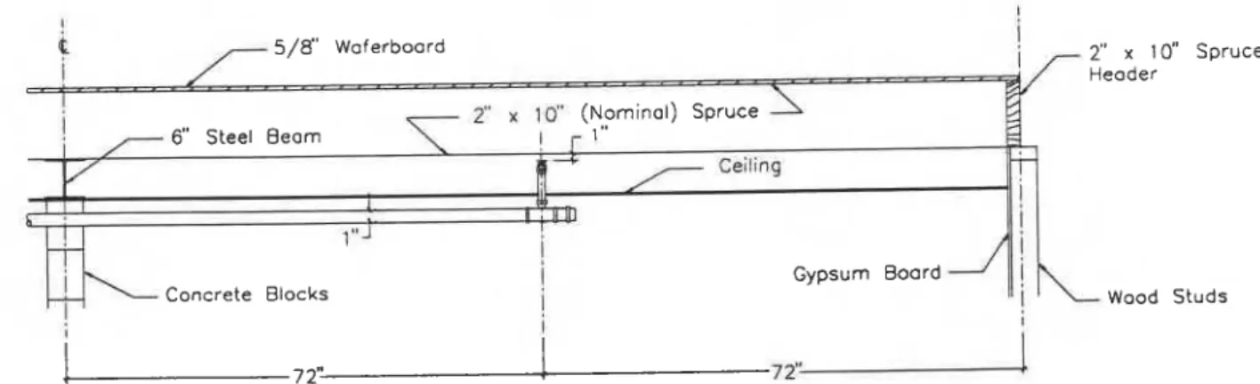
5/8" Waferboard j L- - \ I 2" r 10" (Nominal) Spruce /-- 6" Steel Beam ! r l "i4
r
Ceiling 7- t I I b I ,11101!
I.
" 1 I I Gypsum Board1
I
k-
Wood studsFigure 2. Cross-section of the ceiling assembly viewing normal to the joists showing the relatiave position of the spnnkler.
Lougheed & R i i s o n , Sprinklers in Combustible Concealed Spaces
chromel-alumel thermocouples installed 2 in. (51 mm) below the bottom surface of the floor- ing. In the first test, the thermocouples were mounted in alternate joist spaces a t distances of 3, 9, 15 and 21 R (0.9, 2.7, 4.6, and 6.4 m) from the support wall. In the second test, further thermocouples were included in the joist space on which the ignition source was centered a s well as a t the sprinklers.
Other instrumentation included a closed circuit event timer to record sprinkler activation times, a paddle-wheel flowmeter (Signet Accum-U- Flow) to monitor water flow and a digital pres- sure gauge to measure the water pressure. Video records were made with two cameras located to view the ceiling assembly parallel and normal to the line of the joists.
Test Procedure
The sprinkler piping was precharged with water by using the inspector's test connection a t the hydraulically most remote point.
The propane sand burner was ignited and the flame was allowed to develop fully (approxi- mately 10 s ) before t h e commencement of timing for the test. The burner was set to deliv- er 3.4 x 10⁵ Btuhr (100 kW) output. The burner was turned off after 3.5 minutes of fire expo- sure.
The sprinkler control valve was adjusted to maintain 12 psi (87 kPa) pressure a t the valve after the operation of the first sprinkler and a s
additional sprinklers opened. The minimum allowable residual pressure a t that location for
4 sprinklers operating in this configuration is 10.5 psi (76 kPa). This minimum allowable pres- sure is based on the NFPA 13 criterion that 7 psi (kPa) pressure be maintained a t the most remote sprinkler. At the minimum operating pressure, the calculated total flow with fopr sprinklers operating is approximately 62 US gpm (235 Lfmin).
Test
1Both the floor membrane and the ceiling panels (plywood) had high flame spread ratings. The flame spread ratings of 232 for the waferboard subfloor and 211 for the ceiling panels were measured in the standard tunnel test. The flame front moved rapidly along the ignited joist space with fire visible out of the open end, 24
fk
(7.3 m) from the burner position, within 97 s and flames extending 3 m outside the assembly after 176 s.
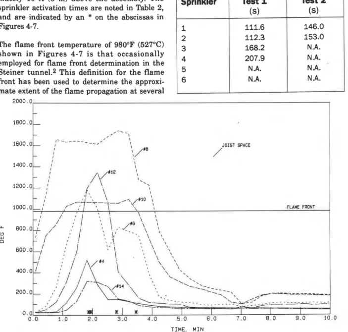
As noted previously, thermocouples were mounted in alternate joist spaces to monitor temperatures. In Test 1, the ignition source was centered on Joist Space 9 (with no thermocou- ples) and extended partially into Joist Spaces 8 and 10. After sprinkler activation, the maxi- mum temperatures decreased rapidly in the direction normal to the joists. This is illustrated in Figure 4 by the temperature profiles mea- sured by the thermocouples mounted in the
5/8" Waferboard 7 (Nominal) 6" Steel Beam T Bar ceilingJ 1- 0 2
Figure 3. C r ~ s S - S e ~ t i ~ n of the ceiling assembly viewing parallel to the joists showing the relative positions of the
J. of Fire Prot. Engc, 1 (2), 1989, PP 4462
first, third and fiRh joist spaces on either side of the ignition source and 3 f t (0.9 m) from the support wall. Temperatures did not exceed 600°F (315°C) by the fifth joist space.
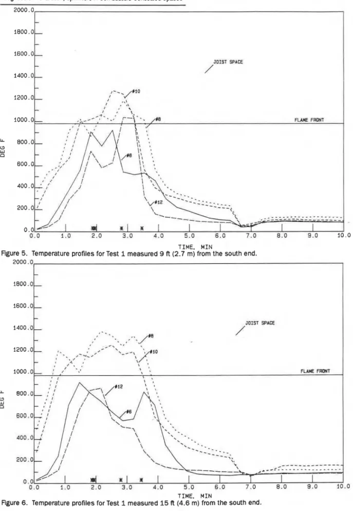
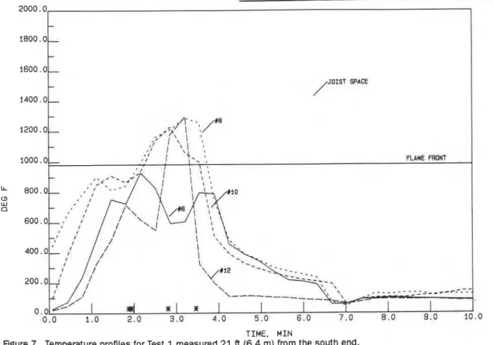
Figures 5-7 show the temperatures measured a t 9,15 and 21 ft (2.7, 4.6, 6.4 m) from the south wall in the first and third joist spaces on either side of the ignition source. These profiles indi- cate that a high temperature jet moved rapidly along the channel formed by the joists. At 75 s, the flame was observed a t the open end of Joist Space 8, and by 3 min, fire was emerging from Joist Spaces 7-12 with flames reaching approxi- mately 10 f t (3 m) above the assembly. The sprinkler activation times are noted in Table 2, and are indicated by an
*
on the abscissas in Figures 4-7.The flame front temperature of 980°F (527°C) shown in Figures 4-7 i s t h a t occasionally employed for flame front determination in the Steiner tunnel.2 This definition for the flame front has been used to determine the approxi- mate extent of the flame propagation a t several
times during the test (Figure 8). The rapid development of the flame front along the chan- nels formed by the joists is illustrated. On the other hand, the flame spread across the joists was much slower.
Four sprinklers were eventually activated in Test 1. An activated sprinkler is indicated by the large circles in Figure 8 with the radius, R,
representing t h e maximum distance t h e droplets would attain under ideal conditions. Assuming the droplets fall a distance y (in this
TIME. M I N
Figure 4. Temperature profiles for Test 1 measured 3 R (0.9 m) from the south end.
Table 2. Sprinkler Activation Times Test 2
(s)
146.0 153.0 N.A. N.A. N.A. N .A. Sprinkler 1 2 3 4 5 6 I Test 1(9
111.6 112.3 168.2 207.9 N .A. N .A.Lcugheed & Richardson, Sprinklers in Combustible Concealed Spaces 2000.0
TIME. M I N
Figure 5. Temperature profiles for Test 1 measured 9 R (2.7 m) from the south end.
TIME. MIN
J. of Fire Prot. E n g ~ , 1 (Z), 1989, pp 49-62
TIME. MIN
Figure 7. Temperature profiles for Test 1 measured 2 1 ft (6.4 m) from the south end.
- 1200 .o- - 1000.0, FLARE FRONT LL 800.0, a W a - - -
-
* *- .
_-- - -- -
-
-.---. # 8.0 9.00 Seconds 26 Seconds 4 7 Seconds
10.0
6 6 Seconds 8 4 Seconds 108 Seconds
Sprinkler L o c a t i o n s
0
A c t i v a t e d Sprinkier-,
Propane B u r n e r126 Seconds 150 Seconds 210 Seconds
Lougheed & R i i s o n , Sprinklers in Combustible Concealed Spaces S t e e l Yeon 2 3 2 2 21 20 I9 !8 ! 7 16 ! 5 : t 13 12 I! 10 9 8 7 6 5 4 3 2 1 I i I I I : Sprfnkier S y s t e n Wood S t u d Wall @ S p r i n k i e r L o c a t i o n s ob S p r i n k l e r V a t v e @ P r e s s u r e Gauge
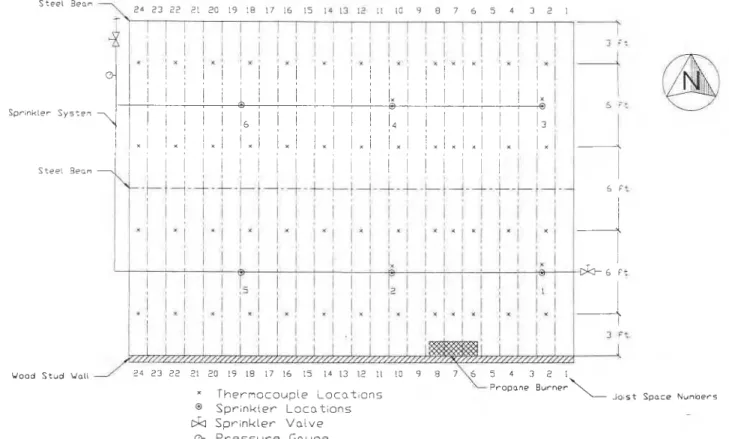
Figure 9. Plan view of the ceiling assembly showing the location of the propane burner, sprinklers and thermocouples for Test 2.
2000.0
TIME. MIN
J. of Fire
Prot.
E n g ~ , f(Z),
1989, PP 49-62'case 5 in. (127 mm)) acted on only by gravity, the maximum distance attained is given by
where g is the acceleration due to gravity, Q is
the nozzle volume flow, and D is the nozzle
diameter.3 (The maximum distance measured experimentally is usually only 75-80% of the idealized estimate.) For the present ceiling con- figuration, the direct sprinkler coverage is limit- ed to a 64 in. (1.6 m) diameter area. Deflected droplets, hot gas turbulence and steam genera- tion in the confined space will extend the effec- tive coverage of the sprinklers.
The sprinkler activation was not sufficiently fast to limit the flame spread along the joist channel. The two sprinklers nearest the fire source did not operate until after the fire had reached the open end of the assembly. The sprinklers did, however, limit the flame spread across the joists and eventually reduced the extent of the fire.
Test 2
In the second test, a low flame spread material (gypsumboard) was substituted for the plywood as the ceiling panels. The propane burner was centered on Joist Space 7. The sprinklers were
also moved to maintain the same relative dis-
tance from t h e burner a s t h e first t e s t . Thermocouples were added in the Joist Space on which the burner was centered, and a t the sprinkler locations. The remainder of the test
arrangement was identical to that in the first
test. The plan view for the assembly used for Test 2 is shown in Figure 9.
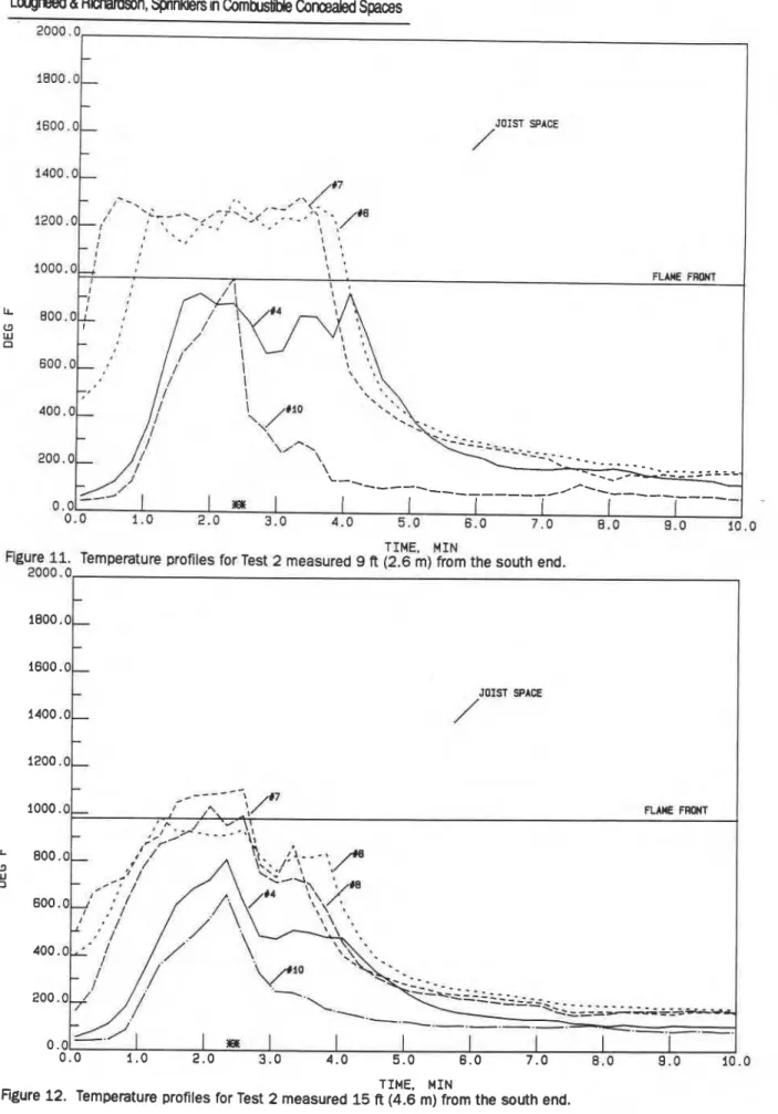
Figures 10-13 show the temperatures measured in the joist spaces (4,6,7,8 and 10) on which the burner was centered. Some thermocouples were damaged during the test, and thus the tempera- ture is not shown for all joist spaces in some fig- ures. The flame front moved along the joist spaces ahead of sprinkler activation. However, the movement was much slower than in the first test with only minor burning at the open
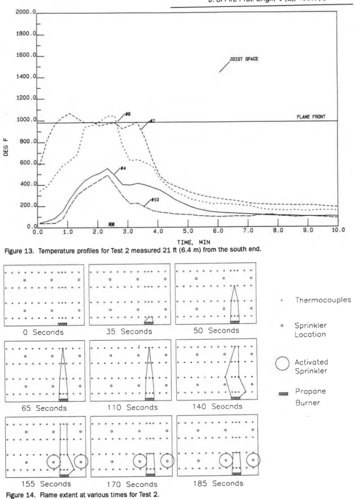
end of the structure. A comparison of the flame extent at several times during Test 2 shown in Figure 14 with the results shown in Figure 8 for
Test 1 further illustrates the slower flame
spread in the second test. For the joist spaces partially exposed to the propane burner, the flame front required 140 s to reach the thermo- couples located at 21 ft (6.4 m) compared with 84 s for the first test. Some fire was observed a t the north end of these spaces after 155 s. The fastest flame spread, as would be expected, was along Joist Space 7 on which the burner was centered with only 65 s required for the temper- ature measured a t the end thermocouple to reach 950°F (527°C). The fire was observed at the north end of this joist space at 98 s with flames approximately 3 f t (0.9 m) above the assembly by 110 s.
The flame also spread across the joists with suf- ficiently high temperatures for the two sprin- klers nearest the burner to operate with the activation times noted in Table 2 and indicated
by an
"
on the abscissas of Figures 10-13. Noother sprinklers were activated during the test. The horizontal flame spread was halted by the two sprinklers which did activate. However, up to 150 s after sprinkler activation was required
before cooling was observed in some areas of the
test assembly (see Figure 10 Joist Space 4). The
temperature at the north end of the assembly
did decrease rapidly after sprinkler activation with no flame observed out the open joist chan- nels &r 225 s.
Discussion
Flame spread along the joist channels can be
compared to a situation reported in the litera-
ture: flame spread along corridor ceilings.4*5~6 In
these tests carried out at the Fire Research
Station in the U.K, a flame from a porous bed
gas burner was allowed to impinge on the closed end of an inverted channel with a variety of noncombustible and combustible ceiling linings tested.
The 1.7 x 10⁵ Btuhr (50 kW) ignition source used in the tests documented by Hinkley et.al.6 with
combustible ceiling materials is comparable to the
-
1400.0- 7 I - - .. .
I '2,,,. 4.
,--' I 1 .<*-.7*.:<. ;-
-'
- -,,.
I , r * I I I ' I ' - 0-.
I ' I I I ' ' ~ O O O . O ~ ' '. FLAME FCRWlLougheed & R i i s o n , Spmkkrs in Combuslitie Concealed Spaces 2000.0
TIME, M I N
Figure 11. Temperature profiles far Test 2 measured 9 R (2.6 m) from the south end. 2000 "0
1
1800.0-
TIME. M I N
Figure 12. Temperature profiles for Test 2 measured 15 ft (4.6 m) from the south end. - 5 8 -
J. of Fire Prot. E n g ~ , f (2), 1989, pp 4462
2000 .0, 1
TIME. MIN
Figure 13. Temperature profiles for Test 2 measured 2 1 R (6.4 m) from the south end.
0 Seconds 65 Seconds 35 Seconds t + + * + + * f + + 1 1 0 Seconds 5 0 Seconds Thermocouples 0 Sprinkler Location
--\:d
* . * + + + * * + + + 140 Seocnds Propane Burner155 Seconds 170 Seconds 185 Seconds
Figure 14. flame extent at various times for Test 2.
Lougheed & Rimson, SpMlWers in Combustible
Concealed
Spaces propane sand burner. The flame in those tests very quickly (approximately 60 s for a 14.8 R (4.5m) length) reached the end of the channel assem- bly and extended 16.5-23 ft (5-7 m) beyond the end of the channel. In Test 1 (reported previously) with the sprinklered ceiling assembly, flames extended up to 10 ft (3 m) beyond the end of the joist channel (24 ft (9 m) length) a t 167 s. The peak temperatures 1470°F (800°C) in the joist channels are comparable to the combustible ceil- ing tests, and considerably higher than the 1llO"F (600OC) obtained with noncombustible lin- i n g ~ . ~ The channel tests also indicated a fast rise, high intensity radiation exposure b 6 . 3 x 10³ Btu/hr/ft2 (20 kWIm2)) to a wood floor with a resulting high flame spread. This is similar to the first test where a rapid flame spread is observed along the combustible ceiling material.
A major difference with the tests reported in this paper compared with the corridor situation is the close proximity of the ceiling to the joist channel which may further limit the air flow to the fire located in the joist spaces. There were indications with the relatively open channel structures that fuel rich combustion dominated with the hot gas layer extending 6-8 in. (150-200 mm) below the ceiling. Ventilation-limited combustion could account for the slow flame spread in the second test with a noncombustible ceiling material even though the flooring material above the ceiling had a high flame spread rating.
The sprinklers did halt the fire spread across the joists, but were ineffective in slowing the fire spread along the joist channels. In fact in Test 1, the fire had already spread beyond the end of the structure by the time the nearest sprinklers opened. The use of a low flame spread material for the ceiling tiles did alleviate the problem to some extent, but did not prevent the fire from spreading to the end of the assem- bly. The steam generated by the contact of the water droplets with the hot fire gases had a sig- nificant effect in the confined spaces and would be expected to suffocate the fire even beyond the direct penetration of the sprinkler droplets.
These tests were nm primarily to examine the
exception for sprinkler protection in concealed spaces formed by ceiling membranes suspended within 6 in. (152 mm) of the joists of a com- bustible ceiling assembly a s permitted by
NFPA
13. The tests conducted indicate that sprinkler protection does not afford adequate protection against fire spread along the joist channels, especially if a combustible material is used for the ceiling panels. However, once the sprinklers are activated, the resulting steam cloud does limit lateral spread of the fire and does s a o - cate the fire beyond the limits of direct sprin- kler spray penetration.
The characteristics for flame spread in the con- cealed ceiling assembly a r e similar to t h a t found for corridors with combustible ceilings. The joist spaces act a s a channel for the rapid transport of the fire gases to the open (north) end of the assembly. For the first test, there was rapid flame spread along the joist channel enhanced by the burning of the combustible ceiling membrane. The extended flame obsefved in the second test was due to ventilation limited combustion i n t h e ceiling assembly. T h e decrease in the extent of the flame once the two sprinklers near the burner were activated was due to suffocation of the fire by steam even though these sprinklers should have had mini- mal or no direct effect on a fire situated near the open end of the assembly.
Further tests are required to determine the spacing a t which adequate control of the fire spread can be obtained. Variations in the sprin- kler system such a s the use of quick response sprinklers or staggered sprinkler layouts should also be considered.
There is a definite need for further protection in ceiling assemblies with concealed spaces. For example, the use of fire stops to minimize flame spread along the joists or filling the space between the suspended ceiling and the joists with noncombustible insulation should be con- sidered. Exception 4 of Subsection 4-4.4.1 does allow for no sprinkler protection for composite wood construction if the joist channels are fire- stopped into volumes not exceeding 160 cu ft
(4.53 m3) or do not exceed 300 sq ft (27.9 m2) channel area. However, this exception stipulates
J. of Fire Prot. Engc, 1 (2), 1989, pp 4962
t h a t the ceilings should be attached directly to the composite wood joist construction, a n d would have to be modified before it could be applied to a suspended ceiling with wood joist construction. Tests a r e required with com- bustible ceiling assemblies to determine the
effectiveness of fire stopping i n controlling flame spread along the joist space for ceilings suspended below the joists.
1. NFPA 13, "Standard for the Installation of Sprinkler Systems", National Fire Protection Association, Qulncy, MA, 1987.
2. CAN4-S 102-M83, "Standard Method of Test for Surface Burning Characteristics of Building Materials", Underwriters Laboratory of Canada, 1983.
3. Wendt, B., and Prahl, J.M., "Discharge Distribution Performance for An Axisyrnmetric Model of A Fire Sprinkler Head", National Bureau of Standards Report, NBS-GCR-86-517,1986. 4. Atallah, S., "Fires in a Model Corridor with a
Simulated Combustible Ceiling, P a r t I
-
Radiation, Tem erature and Emissivity Measurements", &re Research Note 628, Fire Research Station, Borehamwood, 1966.
5 Hinkley P.L.,Wraight, H,G. H. andTheobald, C.R,, '?he Contrlbntion of klames Under Ceilings to Fire S mad in Compartments, Part I
- Incombustible geiiings1', Fire Research Note
712, fire Research Station, Borehamwood, 1968. 6. Hinkley, P.L., a n d Wrai h t , H.G.H., "The
Contribution of Flames ~ n s e r Ceiling8 to Fire
Spread in Compartments, Part I1 - Combustible
Ceiling Linings", Rre Remarch Note 743, Frre
This paper is being distributed in reprint form by the Institute for
Research in, Consrruction. A list of building practice and research publications available from the Institute may be. obtained by writing to
the PubIications Section, Institute for Research in Construction. National Research Council of Canada,, Ottawa, Ontario, KIA OR6.
Ct document est distribue sous forme de M-A-part par 1'Institut de
recherche en construction. On p u t obtenir une lisle des publications de
1'Institut portant sur les techniques ou les recherches en matiEre de
bitirnent en h i v a n t la Section des publications, Institut de recherche
en construction, Conseil national de recherches du Canada, Ottawa