Publisher’s version / Version de l'éditeur:
Interface, Roof Consultants Institute (RCI), 20, November 11, pp. 16-20,
2002-11-01
READ THESE TERMS AND CONDITIONS CAREFULLY BEFORE USING THIS WEBSITE. https://nrc-publications.canada.ca/eng/copyright
Vous avez des questions? Nous pouvons vous aider. Pour communiquer directement avec un auteur, consultez la première page de la revue dans laquelle son article a été publié afin de trouver ses coordonnées. Si vous n’arrivez pas à les repérer, communiquez avec nous à [email protected].
Questions? Contact the NRC Publications Archive team at
[email protected]. If you wish to email the authors directly, please see the first page of the publication for their contact information.
NRC Publications Archive
Archives des publications du CNRC
This publication could be one of several versions: author’s original, accepted manuscript or the publisher’s version. / La version de cette publication peut être l’une des suivantes : la version prépublication de l’auteur, la version acceptée du manuscrit ou la version de l’éditeur.
Access and use of this website and the material on it are subject to the Terms and Conditions set forth at
Wind uplift ratings of mechanically-attached single-ply modified
bituminous roofing systems
Baskaran, B. A.; Sexton, M.; Molleti, S.
https://publications-cnrc.canada.ca/fra/droits
L’accès à ce site Web et l’utilisation de son contenu sont assujettis aux conditions présentées dans le site LISEZ CES CONDITIONS ATTENTIVEMENT AVANT D’UTILISER CE SITE WEB.
NRC Publications Record / Notice d'Archives des publications de CNRC:
https://nrc-publications.canada.ca/eng/view/object/?id=a1448e49-d277-4d59-a97c-987165f1dbb4 https://publications-cnrc.canada.ca/fra/voir/objet/?id=a1448e49-d277-4d59-a97c-987165f1dbb4http://www.nrc-cnrc.gc.ca/irc
Wind uplift ra t ings of m e c ha nic a lly-a t t a c he d single -ply m odifie d
bit um inous roofing syst e m s
N R C C - 4 5 6 7 6
B a s k a r a n , B . A . ; S e x t o n , M . ; M o l l e t i , S .
N o v e m b e r 2 0 0 2
A version of this document is published in / Une version de ce document se trouve dans:
Interface, Roof Consultants Institute (RCI), 20, (11), November, pp. 16-20,
November 01, 2002
The material in this document is covered by the provisions of the Copyright Act, by Canadian laws, policies, regulations and international agreements. Such provisions serve to identify the information source and, in specific instances, to prohibit reproduction of materials without written permission. For more information visit http://laws.justice.gc.ca/en/showtdm/cs/C-42
Les renseignements dans ce document sont protégés par la Loi sur le droit d'auteur, par les lois, les politiques et les règlements du Canada et des accords internationaux. Ces dispositions permettent d'identifier la source de l'information et, dans certains cas, d'interdire la copie de documents sans permission écrite. Pour obtenir de plus amples renseignements : http://lois.justice.gc.ca/fr/showtdm/cs/C-42
,."
mャjHェゥヲゥセゥj「wィイイゥNNᆱ
•'••.ーNァゥセᄋ
one of tbe fastest grow-ing systems for commercial and industrial applications, It occupies the middle ground between the traditional built up roof (BUR) systems and the new generation single ply roof (SPR) systems, Originally developed in Europe, modi-fied bituminous membranes were introduced In the 1970sdefense
wa'fL<
The cap sheet's upper
sャNャGNAGゥ[Nエッゥャエ・Hェセゥエィ
UliIleriHgrarl'-ules, metal foils, or variousllq\lid coatings, Itincreases the membrane's weatherability and UV resistance, Installation of the cap sheet can be done in different ways, It can be torched, hot-mopped, cold-applied, or self-adhered to the base sheet.A· 1.5', B· 2" , C. 0,5"
+-I-!---- Cap shaet seam Cap sheet fully torched , Fastener & plate
- Base sheet seam " - - - Base sheet
- - - Insulation
' - - - Deck
イMMMMMMMMMMMMMMMMMMMセ NEW DEVELOPMENT
Advancements in material research facili-tated development of a new SBS modified bituminous membrane, The manufacturer claims this new generation membrane is heavy duty and that a single membrane layer is expected to perform the function of the tra-ditional base and cap sheets, There is no change in the membrane width - 39-3/8"
(1000 mm) - and top surfaces are coated with colored mineral granules or foils, However, the single-layer modified bitumi-nous sheet has a different thickness and den-sity: 0,2" (5 mm) and 468 pef (7500 kg/m')
Figure 1: Tlvo-ply system with mechanically-attached base sheet (not to scale),
to the North American market. Membranes are made by modifying bitumen with synthet-ic polymers - either styrene butadiene styrene (SBS) or atactic poiypropylene (APP] , They are reinforced with polyester, fiberglass, or a combination of both, This combination enhances the membranes' physical character-Istics and adds セエイ・ョァエィ to the overall system, Conventionally, a mechanically-attached, modified bituminous system consists of two membrane layers - base sheet and cap sheet
(Figure 1), The base sheet is installed as the first layer over the insulation with or without a cover board, Mechanical attachment is used to fix the base sheet to the structural deck. It mcludes fasteners, metal plates of different shapes or sizes, or metal batten strips, At the overlapping, seams are formed either by torchmg or self-adhering, A "cap sheet," as the name suggests, acts as a top layer to the base sheet and may provide a second line of
->.''--Single-ply top sheet Fastener&plate Torched seam
" - - - Single-ply bottom sheet
' - - - Insulation
" - - - , Decl'
. - - - Torched Seam , - - - Single-ply top sheet
GイGnGNjBBGゥセセZゥヲ[[[[[[MMMM Single-ply bottom sheet
セiG
-1:f:::::::=i
_
' Overlap 8"
Figure2: Single-ply, mechanically-attached systems (l" • 25,4mm; not to scale).
16· Interface November 2002
I
4: Seam Torching
s: System Ready for Testing respectively. lypical
mechanical properties (as determined in accordance with CGSB 37 56M97) are as follows: • Maximum Load [kN/m (kilo Newton/ meter)] MD: 16 [1 kif (kilopound/linear foot)]; XD: 15 (l kif) • Ultimate Elongation (%): MD: 74; XD: 68 • Strain Energy (kN/m): MD: 12 (0.8 kif); XD: 9 (0.6 kIf) • Tear Resistance (N): 125 (28 lbf) • Static Puncture (N): 440 (99 lbf)
According to the manu-facturer, the new single-ply, mechanically-attached mod-ified bituminous systems should be used on roofs with slopes greater than three percent. Any roof with slopes of less than three percent must use two-ply systems (refer to Figure
i). The new system is also claiming several advantages
such as: reduced applica- 3: Seam Attachment tion and material costs,
application with less torch-ing, and reduction in con-struction waste.
Nevertheless, there are questions about its wind uplift resistance. To quanti-fy the wind rating of these new systems, experiments were carried out by the National Research Council of Canada (NRCC) and the Special Interest Group for Dynamic Evaluation of Roofing Systems (SIGDERS,
a research group co- Figure3: installation ofa single-ply, mechanically-attached system at the Dynamic Roofing
sponsored by RCI). Facility laboratory.
EXPERIMENTAL APPROACH
overlapped by about 8" (203 mm). Mechanical fasteners Tested System were used at the bottom sheet to secure it to the steelFollowing the manufacturer's installation procedures, deck. Fasteners were 2-7/8" (73 mm) long with a 3"-square the roof applicator installed the system on the SIGDERS (76 mm) metal plate. Of the 8" (203 mm) overlaps, only 4" table. 1.5"-thick (81 mm) ISO insulation boards were loose- (101 mm) were torched to form seams. Fasteners were laid over nominal 22 gao steel deck (Figure2). The single- placed along the seam from 12-inch (305 mm) to 24-inch ply, modified bituminous membrane sheet was unrolled (610 mm) intervals, depending on the system, and expen-over the insulation. To maintain continuity, sheets were ments were conducted on four systems.
November 2002 Interface •
17
---Static Wind Uplift Rating
For the static test, the Factory Mutual (FM) pro-cedure was used at the SIGDERS table'. In the FM load test, an initial pressure of 30 psf (1436 PaJ was applied and maintained for one minute. The pres-sure was then increased at a rate of 15 psf (718 Pal per minute until failure was observed in the test panel. For example, the windstorm classification 1-90is obtained if the test assembly successfully passes the 90 psf (4309 Pal pressure.
Facility
Wind uplift rating investigations for the above were conducted in the Dynamic Roofing Facility lab (DRF) of the National Research Council of Canada
(Figure 3). Using this facility, both static and
dynamic test protocols can be simulated. Three sys-tems were subjected to static test, and the fourth was tested under dynamic conditions.
Dynamic Wind Test Protocol
For dynamic testing, the SIGDERS test protocol' was used. As shown in Figure 4, the SIGDERS dynamic protocol has five rating levels (A to E). To evaluate a roof assembly for a specific wind resis-tance, all the gusts corresponding to Level A must
t
t
t
t
Figure 4: SIGDERS dynamic wind uplift test protocol.
⦅ゥゥヲイZセ
15 " " - - - ' 0 2 3 4 5 6 7 8 Loading Sequence Grou 1 Grou 2QセQ
__
o_-JiJl"
BQQセQ
F
1.75 100 50セUP
21
5/25 105 1.31 79 0.88 250 53 0.44 0 0 0 27 0 ' - - - - L..--lIJOLIII --' 0i
セゥセQ
Qセ"
uJ"
ゥャGャセ
Hr
ro
セ
0.94 150セiNゥャゥャャセ
57 0.83111ft
セ 38 0.31 0 0 19o
0 1.00 0.75 0.50 0.25o
18. Interface November 2002Interface • 19
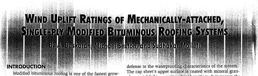
Figure 5: Static wind uplift performance of single-ply,
mechanically-attached system.
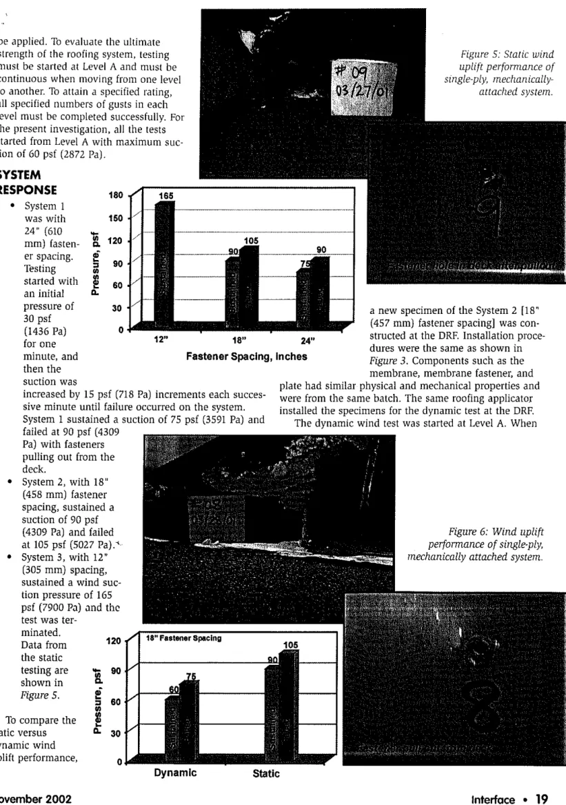
Figure 6: Wind uplift
perfonnance of single-ply, mechanically attached system.
24"
a new specimen of the System2 [18" (457 mm) fastener spacing] was con-structed at the DRF. Installation proce-dures were the same as shown in
Figure 3. Components such as the
membrane, membrane fastener, and plate had similar physical and mechanical properties and were from the same batch. The same roofing applicator installed the specimens for the dynamic test at the DRF. The dynamic wind test was started at Level A. When
Static
18"
Fastener Spacing, Inches
165 12"
o
30 180 150 120i
90セ
セ 60!
30 • System 1 was with 24" (610 mm) fasten-i
120 er spacing.PI
Testingill
90 started with セ 60 an initial -pressure of 30psf (1436 Pal for one minute, and then the suction wasincreased by 15 psf (718 Pal increments each succes-sive minute until failure occurred on the system. System 1sustained a suction of75 psf (3591 Pal and failed at 90 psf(4309
Pal with fasteners pulling out from the deck.
• System 2, with 18" (458 mm) fastener spacing, sustained a suction of90 psf (4309 Pal and failed at 105 psf(5027 Pa).' • System 3, with 12"
(305 mm) spacing, sustained a wind suc-tion pressure of165 psf (7900 Pal and the test was
ter-minated. Data from the static testing are shown in Figure 5.
be applied. To evaluate the ultimate strength of the roofing system. testing must be started at Level A and must be continuous when moving from one level to another. To attain a specified rating, all specified numbers of gusts in each level must be compieted successfully. For the present investigation, all the tests started from LevelA with maximum suc-tion of60psf (2872 Pal.
SYSTEM
RESPONSE
To compare the static versus dynamic wind uplift performance, 0セLBNi1
Dynamic November 2002-subjected to dynamic wind loading, the system sustained 60 psf (2872 Pal suction and failed at 75 psf (3591 Pa). In other words, the system passed all2200 gusts of Level A and failed at the Sequence4at Level B of the SIGDERS load cycle. The observed failure mode was fasteners pulling out from deck. Data from the dynamic testing are shown in
Figure 6.
SUMMARY
Wind performance of newly developed single ply mechanically attached modified bituminous roof assem-blies was investigated in both static and dynamic environ-ments. Simulated wind dynamics by the SIGDERS protocol reduced the wind uplift rating by 30psf (1436 Paj, com-pared to static testing. Fastener pullout was the only observed failure mode irrespective of the static and dynam-ic test. This inddynam-icates that the weakest link was the fasten-er engagement with the deck. Thfasten-ere are two ways to strengthen the link: l) use a high tensile strength deck;
and 2) adapt a fastener that has differently-engineered thread design.
ACKNOWLEDGEMENT
Data presented in this paper are taken from an ongoing joint research project between NRC and Soprema Canada. The authors thank Martin Cote of Soprema Canada and
William Lei of NRC for their help during system installa-tion. •
1. Baskaran, A., and F. Nabhan, (2000), "Standard Test Method for the Dynamic Wind Uplift Resistance of Mechanically Attached Membrane Roofing Systems,"
Internal Report IRC-IR 699, National Research
Council, Canada.
2. Baskaran, A.; Chen, Y., Vilaipornsawai, U. "A New dynamic wind load cycle to evaluate fiexible mem-brane roofs," ASTM,Journal of 'Jesting and
Evaluation 27(4), 1999, pp. 249-265.
ABOUT THE AUTHORS