A Cavity-Stabilized Diode Laser for Dipole
Trapping of Ytterbium
by
David Levonian
Submitted to the Department of Electrical Engineering and Computer
Science
in partial fulfillment of the requirements for the degree of
Master of Engineering in Electrical Engineering and Computer Science
at the
MASSACHUSETTS INSTITUTE OF TECHNOLOGY
September 2015
c
○
David Levonian, MMXV. All rights reserved.
The author hereby grants to MIT permission to reproduce and to
distribute publicly paper and electronic copies of this thesis document
in whole or in part in any medium now known or hereafter created.
Author . . . .
Department of Electrical Engineering and Computer Science
August 18, 2015
Certified by. . . .
Vladan Vuletić
Lester Wolfe Professor of Physics
Thesis Supervisor
Accepted by . . . .
Dr. Christopher J. Terman
Chairman, Masters of Engineering Thesis Committee
A Cavity-Stabilized Diode Laser for Dipole Trapping of
Ytterbium
by
David Levonian
Submitted to the Department of Electrical Engineering and Computer Science on August 18, 2015, in partial fulfillment of the
requirements for the degree of
Master of Engineering in Electrical Engineering and Computer Science
Abstract
Bad-cavity lasers using a gain medium with a narrower linewidth than the laser cavity have the potential to achieve very narrow linewidths and extremely long coherence times. Such lasers could serve as active frequency standards or enable very-long-baseline interferometric telescopes at optical frequencies. The 6s6p3P
0 to 6s21S0
ground state transition in 171Yb is a promising candidate for the gain medium of a
bad-cavity laser due to its 44 mHz linewidth. For ytterbium to be used efficiently as a gain medium, its inhomogeneous broadening must be suppressed to a level lower than the linewidth of its gain transition.
In this thesis, I design, implement, and characterize an optical lattice trap for ytterbium atoms. The trap consists of a diode laser which is frequency stabilized to an adjustable-length cavity where the ytterbium atoms are trapped. The length of this cavity is then locked by comparison of the laser frequency to a stable reference cavity. The resulting standing wave has high enough intensity that the recoil energy of the gain transition is smaller than the energy spacing between motional modes of the trapped atoms. This situation is known as the Lamb-Dicke regime and means that there is an absence of recoil broadening. The large spacing between motional modes of the trap also enables sideband resolved cooling of the atoms, which allows cooling to temperatures of 3 𝜇𝐾, near the ground state of the trapping potential. Additionally, if the wavelength of the optical lattice is chosen to be at the magic wavelength for ytterbium, where the relative AC Stark shift for the two levels of the gain transition is zero to first order, there is no broadening due to varying intensity in the trap. Since the Doppler effect, recoil broadening and the AC Stark shift are the main sources of inhomogeneous broadening, this trapping scheme is expected to suppress inhomogeneous broadening to a level of 1 Hz.
Thesis Supervisor: Vladan Vuletić Title: Lester Wolfe Professor of Physics
Acknowledgments
I would like to thank the senior grad students on the project, Boris Braverman and Akio Kawasaki, and our postdoc, Daisuke Akamatsu, for help inside and outside the lab, stimulating conversation, and wise mentoring. I would like to thank my current labmates Andre Heinz, Grace Zhang and Chris Sanfilippo and my former labmates Yasunari Susuki and Tamara Sumarac. I thank my advisor Vladan Vuletić for his valuable experimental and professional advice and my academic advisor Charlie Sodini. I would also like to thank the MIT department of electrical engineering and computer science for their financial support and top notch training in electrical engineering and the MIT physics department for the education they gave me. I would like to thank group members, Zach Vendeiro, Hao Zhang, and Kristi Beck, and Professors Baldo and Ram for the various bits of scientific advice they gave me. I wouldn’t have been able to do it without the support of my parents, Mark and Nancy, and my brother Matt.
Contents
1 Introduction 13 1.1 Technical Challenges . . . 18 1.2 Thesis Contributions . . . 19 2 Superradiance 23 2.1 Theory of Superradiance . . . 242.1.1 Classical Treatment of the Bad-cavity Laser . . . 26
2.1.2 Quantum Treatment of Transient Superradiance . . . 29
2.2 Experimental Implementation . . . 32
2.2.1 Trapping . . . 33
2.2.2 Cooling . . . 34
2.3 Requirements for the Optical Lattice . . . 37
2.3.1 Heating . . . 38
2.3.2 Magic Wavelength . . . 40
3 Laser Construction 43 3.1 Laser Diode and Optics Configuration . . . 44
3.2 Output Coupling . . . 48
3.3 Intrinsic Linewidth . . . 49
3.4 Optical Feedback . . . 51
3.5 Current Controller . . . 53
3.6 Temperature Controller . . . 54
4 Optical Cavities 63
4.1 Coupling Light to Cavities . . . 65
4.2 Reference Cavity . . . 66 4.3 Science Cavity . . . 68 4.4 Pound-Drever-Hall Locking . . . 68 5 Laser Feedback 75 5.1 Feedback . . . 75 5.2 Frequency Discriminator . . . 78
5.3 Lockbox Design and Optimization . . . 82
5.4 Piezo Feedback . . . 89
5.5 Initial Locking . . . 91
5.6 RF Feedback . . . 92
5.7 Lock Performance . . . 92
List of Figures
1-1 Superradiant vs Conventional Laser . . . 17
2-1 Phase diffusion caused by spontaneous emission . . . 25
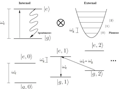
2-2 The ladder of Dicke states . . . 31
2-3 Ytterbium transition wavelengths and linewidths. . . 32
2-4 Positioning of the optical lattice beam and the MOT . . . 34
2-5 Sideband resolved cooling . . . 36
3-1 The a schematic of the entire lattice trapping system. . . 45
3-2 A labeled diagram of the lattice laser and its splitting station. . . 46
3-3 The beam profile of the laser beam at various points. . . 49
3-4 Frequency Spectral Noise Density . . . 51
3-5 Optical feedback regimes . . . 52
3-6 Voltage reference, filtering, primary current source, and current monitor. 53 3-7 Modulation path, piezo output, initial filters and regulators. . . 54
3-8 Current Controller Noise Spectrum . . . 55
3-9 Laser chip heat flows . . . 55
3-10 Schematic Bode plot of the temperature controller system . . . 58
3-11 Temperature controller thermistor current supply and buffer . . . 58
3-12 Temperature controller proportional-integral controller . . . 59
3-13 Temperature controller TEC driver . . . 60
3-14 Step response of the temperature controller . . . 60
4-1 PDH schematic . . . 64
4-2 Reference cavity resonance vs temperature . . . 67
4-3 Cavity Reflection Terms . . . 69
4-4 PDH error signals . . . 71
5-1 Laser feedback loop schematic . . . 76
5-2 The frequency spectral noise density of the laser . . . 77
5-3 Capacitively coupled avalanche photodiode circuit . . . 80
5-4 The loop gain of the PDH lock . . . 84
5-5 Lockbox input buffer and filter . . . 85
5-6 Lockbox PI controller . . . 86
5-7 Lockbox transfer function . . . 87
5-8 Laser mount transfer function . . . 88
5-9 Laser mount schematic . . . 89
5-10 HV Amplifier Input . . . 90
5-11 HV Amplifier Output . . . 90
5-12 Piezo transfer function . . . 91
5-13 Lead-lag filter transfer function . . . 93
5-14 Transmitted Light Spectral Noise Density . . . 94
5-15 PDH error spectral noise density . . . 95
List of Tables
1.1 Linewidths of cavities, atoms and lasers. . . 15 5.1 PDH RF components SNR, gain, and bandwidth . . . 82
Chapter 1
Introduction
Atomic clocks are the most precise time-keeping instruments in the world [1][2][3]. They rely on the fact that the frequency of an electron oscillating between two atomic orbitals does not vary between atoms of a particular isotope and is constant in time. If an atom at rest in the lab frame is shielded from external electric and magnetic fields and collisions with other atoms, the only thing that can perturb the frequency of its electronic transitions is the relativistic effect of gravity 1 [4].
Electron oscillations between atomic orbitals do not last indefinitely. The oscil-lation lifetime is determined by how fast the electrons radiate away their energy as electromagnetic waves, which is in turn determined by how much the center of the electron cloud moves during the oscillation. Large movement of charge during the oscillation produces higher amplitude waves which radiate energy away faster. Since a quickly decaying oscillation produces a broader Fourier-transformed frequency peak, atomic clocks usually use electronic transitions with long lifetimes. Alkali-earth-like elements like ytterbium and mercury have dipole-forbidden transitions between their excited and ground states. Electron transitions between these states have near zero movement of the center of charge and take a long time to decay. One transition in ytterbium takes 3.6 seconds to decay which corresponds to a frequency linewidth of 44 mHz [5]. Since the frequency of the transition is 519 THz, this corresponds to a 1Atomic clocks on GPS satellites are compensated for this effect, as well as relativistic effects
timekeeping uncertainty of 10−18 after 100 seconds of averaging 2 for a single atom
with a lifetime-limited interrogation time.
In order to turn electron oscillations between atomic energy levels into a usable time-keeping signal, atomic clocks tune a very stable clock laser to the clock transition frequency by searching for the frequency that is the most effective at exciting an electron to the excited clock state. To measure how many atoms have been excited by the laser, clock experiments usually use another laser to excite electrons from the upper state to another, shorter-lived excited state and then measure the fluorescence as they decay back to the ground state. Over multiple experimental cycles, the clock laser can be tuned to produce the greatest fluorescence signal. The clock laser can then be used to stabilize an optical frequency comb, which in turn produces a very stable signal at frequencies in the MHz, suitable for conventional electronics [1].
The linewidth of the clock laser has a big effect on the performance of the atomic clock. If we tried to center a laser that produces frequencies over a 100 Hz range on the 44 mHz wide transition in Yb, there would be very little contrast between the laser frequency centered on the clock transition and the laser frequency centered 1 Hz away from the clock transition [6]. In this case, we would have to average over many probing cycles to achieve a precision limited by the linewidth of the transition, not the laser.
Conventional lasers have been produced with frequency linewidths as narrow as 40 mHz [9][10]. However, the linewidth of conventional lasers is fundamentally limited by the Schawlow-Townes limit [11]
Δ𝜈 = ℎ𝜈4𝜋P𝜅2
out
where 𝜅 is the cavity loss rate, ℎ𝜈 is the photon energy, Δ𝜈 is the full-width at half maximum (FWHM) of the laser line and Pout is the power output of the laser. Since
we cannot increase the power of lasers indefinitely, the only improvement can come from having a narrower cavity linewidth. While great strides have been made in cavity 2To put this in perspective, a clock with this precision would gain or lose at most one second in
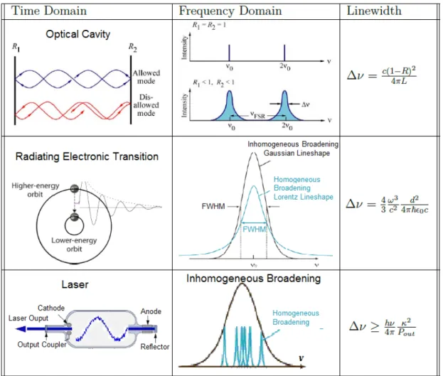
Table 1.1: A comparison of the linewidths of cavities, atoms, and lasers. In cavities, only wavelengths that fit evenly in the cavity resonate and are transmitted. [7] The reflectivity of the mirrors determines how precise the fit needs to be and thus the linewidth of the transmission peaks. An atomic transition emits a wave that exponen-tially tapers off. In the frequency domain this creates a Lorentzian lineshape whose width is inversely proportional to the lifetime of the emission (homogenous broadening.) A laser is made up of many radiating atoms at slightly different frequencies. Together, they emit light with a Gaussian lineshape (inhomogeneous broadening) [8].
stability, cavities have limitations of their own, such as Brownian motion of their mirrors [12]. Other clever tricks like locking the laser to a passive reference cavity with feedback can produce narrower lasers, but are still ultimately limited by the linewidth of optical cavities.
Therefore, to exploit narrow linewidth atomic transitions for more accurate time-keeping, we need to develop narrower linewidth sources of light. Bad-cavity lasers are one potential source. In conventional lasers, atoms in the gain medium emit photons one at a time into an oscillating electric field in the laser cavity. The emission events happen quickly compared to the rate at which photons leak out of the cavity, so the phase of the laser beam is determined by the phase of the electric field inside the cavity.
In bad-cavity lasers, all the atoms in the gain medium oscillate at once, in phase with each other, in a phenomenon known as superradiance 3. Emission of photons
happens very slowly compared to the rate at which photons leak out of the cavity. This means there are on average very few photons circulating in the cavity and the phase of the emitted light is mostly determined by the collective phase of the emitting atoms. In this bad-cavity limit, the linewidth of the laser is determined by the linewidth of the atomic transition powering it, rather than the quality of the cavity [13][14]. The linewidth of the emitted light depends on the linewidth of the atomic transition of the gain medium, not the linewidth of the cavity.
A superradiant laser using a narrow linewidth atomic transition would produce narrow linewidth light free of drifts caused by a changing laser cavity. This absolute stability means it could be used as an active frequency reference, becoming both the atomic reference and clock laser of an atomic clock. More conventionally, such a narrow linewidth laser would allow atomic clocks to reach higher precisions with less averaging time. The ultimate goal of our lab is to build a superradiant laser with a gain medium of ytterbium atoms to realize these time keeping advantages.
Figure 1-1: Superradiant vs Conventional Laser: a) In a conventional laser, the phase of the wave is stored in the electric field of the cavity and is sensitive to mirror vibrations. b) In a superradiant laser, the phase of the laser is stored in the phase of the gain medium, making the laser less sensitive to mirror vibration [15].
1.1
Technical Challenges
In a superradiant laser, the coherence between the atoms of the gain medium is maintained by their interaction with photons in the cavity. For superradiant collective emission to occur, photons need a high probability of interacting with several atoms before leaving the cavity. A factor C known as the cooperativity compares the atom-photon interaction rate with the rate at which atom-photons leave the cavity or are scattered incoherently by atoms.
𝐶 ≡ 𝑔 2 𝜅𝛾
where 𝑔 is the single photon Rabi frequency, 𝜅 is the cavity loss rate and 𝛾 is the inverse lifetime of the atomic state. If 𝑁𝐶 > 1, where N is the number of atoms in the gain medium, then photons emitted by each atom are more likely to encounter other atoms than they are to leave the cavity, and superradiant lasing can occur. In addition to this condition, the gain medium of a bad-cavity laser must be spectrally narrower than its cavity 𝛾 ≪ 𝜅. The long lifetime of the transition in Yb atoms guarantees that 𝛾 is small. 𝜅 depends primarily on the mirrors of the laser cavity: higher reflectivity mirrors mean longer photon lifetime which reduces 𝜅. 𝑔 describes the rate of interaction between photons and atoms. In order to make 𝑔 large, we need light to be highly focused on the atoms. Our experimental cavity4 is designed with
highly reflective mirrors and a fundamental mode that focuses down to a narrow waist where it can strongly interact with atoms. These geometric factors, together with the long lifetime of the ytterbium transition, make superradiant lasing possible.
These conditions are not sufficient for superradiance, however; the interaction of all the atoms with the cavity photons must be identical to support superradiant lasing. If the energy levels of some atoms are slightly shifted, then their electrons will oscillate at different rates. This will destroy the coherence of the collective atomic state - a condition necessary for superradiant lasing. Processes that reduce the degree to which all the atoms radiate collectively are called inhomogeneous broadening. There are two primary causes of inhomogeneous broadening in our experiment. One is the AC Stark
shift, the change of atomic orbitals’ energies in the presence of light and consequent impact on the frequency of transitions. If different atoms of the gain medium are exposed to different intensities of light, then the energy levels of the clock transition will vary and different atoms will radiate at different frequencies. The second cause of inhomogeneous broadening is the Doppler shift. Atom velocity can vary due to finite temperature or due to recoil from emitting photons. If some atoms are moving at different velocities then they will emit different frequencies of light, destroying the collective effects. This increase in linewidth is known as Doppler broadening.
To prevent Doppler broadening, we would like to trap atoms in a place where the laser cavity mode is most intense and prevent their relative movement. The most effective way to tightly confine atoms in a small space is with an optical lattice of counter-propagating laser beams. This presents a conundrum: we would like to trap atoms with lasers to prevent Doppler broadening, but exposing them to light will cause AC Stark shifts. Fortunately, there is a wavelength of light, known as the magic wavelength, which shifts the two atomic energy levels of the clock transition by the same amount 5. An optical trap operating at this wavelength can trap atoms and
prevent Doppler broadening without causing Stark shifts in the atoms.
1.2
Thesis Contributions
My master’s thesis is the implementation of an optical trap for ytterbium atoms at the magic wavelength. By bouncing laser light between the two high-reflectivity mirrors of the superradiant laser cavity 6, we form an optical lattice. Atoms are attracted to
the intensity maxima of this beam of light. Atoms are attracted to the anti-nodes of the standing wave, which form pancake shaped potential wells, defined by the extent of the beam in the radial dimensions and the nodes and anti-nodes of the beam in the axial direction. The sharp potential wells in the axial direction lead to large energy separation between quantized motional modes of the trapped atoms. If the difference
5i.e. the first order shifts in intensity will be the same.
6The science cavity mirrors are designed to be highly reflective both at the magic wavelength of
between these modes is larger than the kinetic energy of recoil from emitting a photon, the atoms will be unable to recoil, a condition known as the Lamb-Dicke regime. An additional cooling laser can create velocity-dependent slowing of the atoms, which cool atoms down, eliminating the Doppler shift due to thermal velocity. The cooling laser is turned off during the superradiance experiment to prevent AC Stark shifts.
The main challenge in creating an optical lattice in a cavity is control of the laser’s frequency. Although lasers emit primarily one frequency of light, the frequency drifts and jumps on a time scale of microseconds. In addition to causing AC Stark shifts in the atoms, these deviations cause the laser to drift in and out of resonance with the optical cavity, changing the intensity of the optical lattice, and exciting atoms to nonzero velocities. While the cooling laser is on, these excited atoms are quickly cooled back down, but during the main experiment, the excited atoms can cause Doppler broadening and interfere with superradiant lasing.
The Pound-Drever-Hall (PDH) frequency lock is a way to keep a laser’s frequency stable [16]. It does this by using feedback to keep the laser close to the resonant frequency of a stable optical cavity. If light shines on the cavity at the frequency of a resonant mode, it bounces between the mirrors such that it is transmitted. Otherwise the light is reflected. If the mirrors are highly reflective, the range of frequencies that are transmitted through the cavity is very small, which makes it useful for keeping a laser’s frequency very stable.
Predecessors of the PDH locking scheme rely on measuring the intensity of the transmitted light through the cavity to measure the frequency of the laser [17]. If the laser frequency moves, then the intensity of the transmitted light changes, and corrective action can be taken. However, if the power of the laser fluctuates, the system may be fooled into thinking the laser frequency has moved. This method also has a bandwidth limited by the linewidth of the cavity: the frequency is only corrected once the amount of light in the cavity has diminished sufficiently to be detected.
The PDH lock avoids these sources of error by using the phase of the light instead of its intensity. The laser is first sent through a modulator which creates two additional frequencies of light, equally spaced above and below the main laser frequency. When
the main laser frequency on resonance, the two side frequencies are reflected back with opposite phases. The reflected light is collected and then mixed back to the central frequency by another modulator and cancel each other out, because they have opposite phases. Even a slight change in the main laser frequency changes the phases of the side frequencies and stops them from canceling. This signal is used as feedback to adjust the laser. This makes PDH locking at once extremely sensitive to frequency fluctuations and immune to intensity fluctuations, because when the laser is on resonance the error signal is zero, regardless of intensity. The PDH lock bandwidth also exceeds the cavity linewidth, as it looks at the reflected signal, which is a combination of light from the cavity and laser light. Frequency drifts immediately cause detectable interference between the two.
My optical lattice laser uses two separate PDH locks to reduce inhomogeneous broadening due to the trapping laser. The first PDH lock keeps the laser resonant with the mode of the superradiant laser cavity where the ytterbium atoms are trapped. This way, there are no changes in the intensity of the optical lattice due to drifts in laser frequency. The length of this cavity is adjustable by piezoelectric stacks to allow greater flexibility in the experiment. Because the resonant frequency of the superradiant laser cavity can vary, I use a second PDH lock to a reference cavity to keep the optical lattice at the magic wavelength. The error signal of the second PDH lock is fed back to the piezos of the superradiant laser cavity. If the resonant mode of the laser cavity drifts from the magic wavelength, the first PDH lock pulls the laser with it. The second PDH lock detects this change in laser frequency and corrects the cavity length.
In my masters thesis, I first analyze the requirements for an optical lattice trap in a superradiance experiment. I then design and build the trapping laser and the two PDH locks needed to keep it at the magic wavelength and on resonance with the superradiant laser cavity. Finally, I measure its performance by comparing it to a separate, low-drift laser in our lab, and show that it meets the requirements of absolute and short-term stability.
Chapter 2
Superradiance
A laser has two essential elements: a gain medium, which amplifies light through stimulated emission, and a cavity, which confines the laser light. The effects of the gain medium and cavity both depend on the frequency of the light. For example, a typical cavity might consist of two partially reflective mirrors, which have a frequency response of 𝐹(𝜔) = ⃒ ⃒ ⃒ ⃒ 1 1 − 𝑅𝑒𝜔𝐹 𝑆𝑅𝑖𝜔 ⃒ ⃒ ⃒ ⃒ 2
where 𝑅 is the mirror reflectivity, 𝜔 is the frequency of incident light, and 𝜔𝐹 𝑆𝑅 is the
free spectral range of the cavity. Likewise, a typical gain medium might be an excited atomic gas. In the case of a homogeneously broadened gain medium, the frequency response would be 𝐺(𝜔) = 𝑔 1 +(︁(𝜔−𝜔 0) 𝛾 )︁2
where g is the gain at the peak gain frequency 𝜔0 and 𝛾 is the linewidth of the gain
transition.
In conventional lasers, the cavity has a narrower frequency response than the gain medium. As a result, the cavity determines the lasing frequency and linewidth. This means that fluctuations in cavity length caused by vibrations affect the laser’s frequency. In precision measurement applications, it is important for the laser’s frequency to be as independent as possible from the environment.
A bad-cavity laser has a gain medium with a linewidth narrower than the linewidth of its cavity. This can be achieved with long lifetime transitions (and correspondingly narrow gains) in rare-earth-like elements like ytterbium and mercury. A laser using these atoms as its gain medium lases at the linewidth of the atoms not the cavity. Also, since the lasing frequency depends on the frequency of the atomic transition, it is relatively insensitive to changes in cavity length [18][19][20].
In this chapter, we first derive the narrower linewidth enjoyed by a bad-cavity laser classically. Then we treat the gain medium using quantum mechanics to find the transient behavior of the superradiant laser. The long lifetime of the transition means that the atoms all undergo stimulated emission, driven by their collective field. Unlike a conventional laser, where atoms emit photons quickly and independently from one another, the atoms of the superradiant laser radiate in sync with each other. Since the power of the light is determined by the square of the electric field, the synchronous radiation of the atoms boosts the power of the laser enormously. This is fortunate, as the long lifetime of the lasing transition would otherwise cause it to radiate very weakly. Following the theoretical treatment of superradiance, we describe the implementation of a superradiant laser with ytterbium atoms and calculate the characteristics of the optical lattice trap needed for the experiment.
2.1
Theory of Superradiance
In a conventional laser, the electric field inside the cavity can be described with phasor notation as
𝐸 = 𝐸0𝑒𝑖𝜔𝑡
where 𝐸0 is the magnitude of the cavity field, which depends on the square root
of the intracavity intensity, and 𝜔 is the laser frequency. Spontaneous emission events give kicks to this phasor, adding small random vectors to it (see figure 2-1.) When these random vectors are parallel to the main field vector, they manifest as intensity fluctuations. Intensity fluctuations are damped out as the laser gain saturates, quickly returning the intensity to its equilibrium value. Spontaneous emission vectors
Figure 2-1: Spontaneous emission of photons causes phase diffusion in the laser [11].
𝛽 is the electric field phasor, normalized by the single-photon cavity field.
perpendicular to the main vector manifest as fluctuations in the phase of the laser. There is no corrective mechanism that counteracts these fluctuations so they cause diffusion of the phase of the laser over time. In the frequency domain, this phase diffusion becomes the finite linewidth of the laser.
The formula for this linewidth, originally derived by Schawlow and Townes [21] and simplified in a paper by Henry [11], is quite simple. The degree of phase diffusion in a laser is simply the rate of spontaneous emission events divided by the length of the main field vector, which corresponds to the number of intracavity photons and multiplied by one half to account for the fraction of spontaneous emissions that influence intensity instead of phase.
In steady state, the spontaneous emission events balance out the loss of photons through the facets of the laser so the linewidth is the ratio of the cavity loss to the number of circulating photons:
Δ𝜔 = 𝜅 2𝐼0
We can rewrite1 the linewidth in terms of the power output of the laser and the cavity
1Using 𝑃
loss rate as
Δ𝜈 = ℎ𝜈 4𝜋
𝜅2 𝑃𝑜𝑢𝑡
As expected, a narrower cavity linewidth leads to a small laser linewidth.
2.1.1
Classical Treatment of the Bad-cavity Laser
A bad-cavity laser is a laser where the lifetime 𝛾 of individual atoms in the gain medium is longer that the lifetime 𝜅 of photons in the laser cavity. In other words:
𝛾 ≪ 𝜅
The effect of this inequality on the laser linewidth can be interpreted two equivalent ways. Examining the gain medium in the frequency domain, we see that it is very narrow. Using the Kramers-Kronig relations, we can see that the highly-peaked gain leads to a very slow group velocity near its peak. This slow group velocity means that small fluctuations in the field envelope of the laser from spontaneous emission events arrive at the end facet of the laser at a much slower rate. Therefore, the emitted light field sees less phase kicks than it would otherwise.
An equivalent interpretation is that the long lifetime of the induced polarization of the gain medium mean that the polarization of the gain medium is no longer proportionate to the instantaneous electric field. These memory effects can be inserted into the wave equation for the field inside the laser:
𝜕2𝐸 𝜕𝑧2 − 1 𝑐2 𝜕2𝐸 𝜕𝑡2 = 1 𝑐2𝜖 0 (︂𝜕2 𝜕𝑡2[𝑃𝑖𝑛𝑑+ 𝑃𝑠𝑝] )︂
where 𝑃𝑖𝑛𝑑 is the polarization induced by the electric field and 𝑃𝑠𝑝 is the polarization
from spontaneous emission events. The left hand side of the equation can be elucidated by using
the slowly-varying envelope approximation for the electric field in the laser. 𝐿𝐻𝑆= 𝜕 2𝐸 𝜕𝑧2 − 1 𝑐2 [︂ − 𝜔2 ℓ𝐸+ 2𝑖𝜔 𝜕𝐸 𝜕𝑡 ]︂
The right hand side can simplified using the identity
𝜕𝑃 𝜕𝑡 = −𝑖𝜔ℓ𝑃 + 𝜕(𝜔𝜒) 𝜕𝜔 |(𝜔=𝜔ℓ) 𝜕𝐸 𝜕𝑡𝑒 −𝑖𝜔ℓ𝑡
Which is derived in [22]. Dropping the ℓ prefix on omega,
𝑅𝐻𝑆 = −1 𝑐2 [︂ 𝜔2𝜒𝐸+ 2𝑖𝜔(𝜒 + 𝜔𝜕𝜒 𝜕𝜔)𝜕𝐸𝑡 ]︂ − 𝜔 2 𝑐2𝜖 0 𝑃𝑠𝑝
and equating the two sides,
𝜕2𝐸 𝜕𝑧2 + (1 + 𝜒) 𝜔2 𝑐2𝐸(𝑟, 𝑡) + 2𝑖𝜔 𝑐2 (︂ 1 + 𝜒 + 12𝜔𝜕𝜒 𝜕𝜔 )︂𝜕𝐸 𝜕𝑡 = − 𝜔2 𝑐2𝜖 0 𝑃𝑠𝑝 𝜕𝜒
𝜕𝜔 can be redefined in terms of the group index of refraction: 𝑛𝑔𝑟 = 𝑛 + 𝜔 𝜕𝑛 𝜕𝜔 𝜕𝜒 𝜕𝜔 = 2𝑛(𝑛𝑔𝑟− 𝑛) 𝜔
Inserting this into the wave equation, considering only waves traveling in the positive z direction, and dividing through by a factor of 2𝑖^𝑘 we find:
𝜕𝐸 𝜕𝑧 + 𝑛𝑔𝑟 𝑐 𝜕𝐸 𝜕𝑡 − 1 2𝑔𝐸 = 𝑖𝜔 2𝑐𝜖0𝑛 𝑃𝑠𝑝
This equation describes changes in the envelope of the electric field propagating outward with speed 𝑣𝑔𝑟. This differs from the laser considered in the Schawlow-Townes
equation in that fluctuations propagate at the phase velocity, near c, in a conventional laser. The phase kicks that had previously happened with a frequency of 𝜅 now happen with a frequency 𝜅/𝑛𝑔𝑟. Therefore, the linewidth in the bad-cavity laser is reduced by
a factor of 𝑛2
𝑔𝑟. In a homogeneously broadened gain medium, the imaginary part of
the dielectric susceptibility has a Lorentzian frequency response:
𝜒= 𝜒′+ 𝑖𝜒′′ 𝜒′′ = 𝑔 1 + (𝜔−𝜔ℓ 𝛾 )2 𝜒′ = 𝑔( 𝜔−𝜔ℓ 𝛾 ) 1 + (𝜔−𝜔𝑙 𝛾 )2
Where g is the gain per length in the laser. This gives
𝑑𝑛 𝑑𝜔|𝜔=𝜔ℓ = 𝑔 2𝑛𝛾 Given that 𝑛 ≈ 1: 𝑛𝑔𝑟 = 1 + 𝑔𝜔 2𝑛𝛾 = 1 + 𝜅 2𝛾 = 𝛾+12𝜅 𝛾
Therefore, the conventional Schawlow-Townes formula is modified to
Δ𝜈 = ℎ𝜈4𝜋 1
𝑃𝑜𝑢𝑡
(︂ 𝛾𝜅
𝛾+ 12𝜅
)︂2
For 𝛾 ≪ 𝜅 the cavity linewidth is replaced by the gain medium linewidth:
Δ𝜈 ≈ ℎ𝜈4𝜋 𝛾2
𝑃𝑜𝑢𝑡
According to this classical interpretation, a laser using the clock transition in ytterbium can have a linewidth narrower than the good-cavity Schawlow-Townes limit. To achieve this linewidth, however, several other experimental conditions need to be met. First, frequency broadening of the gain profile due to anything but the lifetime of the atoms needs to be suppressed to a level lower than 𝛾 = 44mHz. This so-called inhomogeneous broadening includes variable shifts in the clock transition due to atoms being exposed to different intensities of the optical lattice. Secondly, the cavity resonance frequency needs to be less than a linewidth away from the gain transition. Otherwise, photons
emitted by the atoms will not be confined by the cavity.
2.1.2
Quantum Treatment of Transient Superradiance
In order to realize a steady-state superradiant laser, we need to make sure our cavity resonance frequency is centered on the gain transition. To search for this frequency, we need to use the transient behavior of the superradiant laser. If the atoms in the gain medium start in an excited state and the cavity is in resonance with the gain transition, they will emit a pulse considerably more intense than we would classically expect, scaling with the numbr of atoms squared, N2, rather than N. This behavior is
a signature of superradiance. To demonstrate why this is the case, we first consider two particles with two states each that can interact with the electromagnetic field via a dipole operator which describes the transitions between excited and ground state due to emission or absorption of photons:
⃗ 𝑑= ∑︁
𝑖=1,2
|↑𝑖⟩ ⟨↓𝑖| − |↓𝑖⟩ ⟨↑𝑖|
If we look at the eigenstates of the angular momentum 𝜎𝑧 in one direction and the
total angular momentum operator
𝐽2 = 𝜎2𝑥+ 𝜎𝑦2+ 𝜎2𝑧
where the 𝜎 operators are the sums of the Pauli spin matrices for the two particles, we find that a basis of four states, three of which have 𝐽2 = 1:
|1⟩ = |↑↑⟩ , |0⟩ = √1
2(|↓↑⟩ + |↑↓⟩), |−1⟩ = |↓↓⟩
These are the triplet states. The fourth state has 𝐽2 = 0 and is called the singlet
state:
1 √
If we examine the action of the dipole operator on the triplet states we see that it couples them together in ladder:
⟨1|⃗𝑑|0⟩ =√2, ⟨0|⃗𝑑| − 1⟩ =√2
The coupling between these states a factor of √2 stronger than the dipole coupling between the excited and ground states of a single particle. The singlet state does not couple to any other states through the dipole operator, so it is incapable of radiating photons. However, if both particles start in the excited state, they will radiate two photons faster than two independent excited particles would.
This is the simplest example of superradiance; multiple particles collectively interacting with the electromagnetic field have a basis of states, some of which radiate faster than independent particles (superradiant states), others of which do not radiate at all (subradiant states) [23].
We can extend this result, by considering the Hamiltonian of N atoms interacting with a cavity mode:
𝐻 = ~Ω 𝑛 ∑︁ 𝑗=1 𝜎𝑧𝑗 − 𝐸 · ^𝑑 ^ 𝑑= 𝑛 ∑︁ 𝑗=1 𝑖𝜎𝑦𝑗
where 𝜎𝑖 are the Pauli operators for the pseudospin of the clock transition, ~Ω
is the energy difference between the escited and ground states, 𝐸 is the electric field at the atoms and ^𝑑 is the collective dipole moment of the atoms. Since 𝐽2 = 𝜎2
𝑥 + 𝜎𝑦2 + 𝜎2𝑧commutes with H, we can use the formalism for addition of angular
momentum to define eigenstates of 𝐽2 with eigenvalues 𝑟(𝑟 + 1) where
|𝑚| ≤ 𝑟 ≤ 1 2𝑛
and m is the total angular momentum. These states have a degeneracy of
𝑛!(2𝑟 + 1)
(1
2𝑛+ 𝑟 + 1)!( 1 2 − 𝑟)!
Figure 2-2: Dicke states [23]. The superradiant lasing transitions are the tranisitions between the latter of states where L=N/2.
and ⟨𝑟, 𝑚|𝑖𝜎𝑦|𝑟′, 𝑚′⟩ = 0 unless 𝑟 = 𝑟′, 𝑚 = 𝑚′±1. These states form ladders with
field interaction matrix elements of
⟨𝑟, 𝑚|𝑖𝜎𝑦|𝑔, 𝑚 ∓1⟩ =
1 2
√︁
(𝑟 ± 𝑚)(𝑟 ± 𝑚 + 1)
The spontaneous radiation rates are given by the square of the matrix elements:
𝐼 = 𝑁𝐶𝛾(𝑟 + 𝑚)(𝑟 − 𝑚 + 1)
The mean time for the entire superradiant pulse is simply the sum of the mean emission times of each transition
¯ 𝑇 = 1 𝑁 𝐶𝛾 + . . . + 4 𝑁2𝐶𝛾 + . . . + 1 𝑁 𝐶𝛾
This harmonic sum can be approximated as
¯
𝑇 ≈ ln(N) 𝑁 𝐶𝛾
Figure 2-3: Optical transition frequencies and linewidths of ytterbium. The clock transition is 578 nm. The cooling transitions are 399 and 556nm.[24]
Assuming optimal loading into the trap, there should be 10,000 atoms in the optical lattice. 𝐶 = 0.1 and 𝛾 = 44mHz. This gives a superradiant pulse duration of 250ms. In order to observe superradiant pulses, the rate at which the phase of individual atoms decays, known as T2 must be longer than the length of the superradiant pulses.
2.2
Experimental Implementation
Ytterbium is an excellent element for implementing a superradiant laser. It has two transitions that are good for optical cooling 2 at 555.8 nm and 398.9 nm. It also has
a very narrow transition from the 6s6p3P
0 sublevel to the ground state at 578.4 nm,
which has a small dipole moment, so it radiates very slowly.
2i.e. they are fairly broad in frequency and the electrons quickly relax back exclusively to the
2.2.1
Trapping
In our experiment, we use an electrically heated sample of ytterbium to produce a beam of atoms. We then slow and trap these atoms in a magneto-optical trap (MOT), first with a combination of 399 nm and 556 nm light, which can catch atoms with a greater spread of velocities, and then at 556 nm which is a narrow transition more suitable for cooling already-trapped atoms to a lower temperature. [25] Once the atoms are in the second MOT they have a temperature of 30 𝜇𝐾. From the second MOT, they are loaded into a red-detuned optical lattice which is produced by a standing wave between the mirrors that will be used for the superradiant laser.
The superradiant laser cavity must have room for the initial magneto-optical trap while also having regions where atoms will have large coupling to the field mode. Since enhanced coupling is achieved by confining the cavity mode to a smaller space to produce high fields, these two requirements seem to be at odds with one another. However, several cavity designs can achieve high coupling between atoms and cavity modes without being too small. For example, a confocal cavity can be large, but concentrate the cavity field at its focus to a region several wavelengths across. Confocal cavities can be difficult to align however, so we use an asymmetric design with one highly curved micromirror, etched with a CO2 laser and one larger, flatter mirror.
This design is easier to align, but preserves a region of intense cavity field near the smaller mirror that allows high coupling to atoms.
To create the conditions for superradiant lasing, we need to trap the atoms in a potential created by optical dipole forces from light at the magic wavelength. We can then use sideband-resolved Doppler cooling to cool these atoms into the motional ground state of the potential. To use the atoms as the gain medium for a superradiant laser, all this must occur in an optical cavity with a sufficiently high coupling constant. One way to trap the atoms in a laser cavity and make the cooling and trapping process easier is to use the science cavity to make the dipole trap as well.
Figure 2-4: Positioning of the optical lattice beam and the MOT. The counterprop-agating beams of the MOT in two of its dimensions are formed by bouncing the trapping light off the surface that the smaller cavity mirror is imbedded in. Credit to poster designed by Boris Braverman and Akio Kawasaki.
2.2.2
Cooling
In this case, we couple our trapping laser to a fundamental mode of the science cavity, forming a standing wave inside the cavity. Since our trapping laser is red-detuned, atoms are attracted to regions of high average field intensity. We can model these forces with a trapping potential that is linear with the intensity of the trapping light [26]: 𝑈𝑑𝑖𝑝𝑜𝑙𝑒 = 𝛼𝐼 2𝜖0𝑐 = 2 × 10 −8eV𝜇m2 𝑊 𝐼
When atoms are near the minima of the trap, the potential formed by this standing wave of light can be approximated by a series of anisotropic harmonic oscillators with associated frequencies, 𝜔𝑥, 𝜔𝑦, 𝜔𝑧, the trapping frequencies in each dimension. The
the trapping potential and the mass of the atom. 𝜔𝑥 = √︃ 𝜕2𝑈 𝜕𝑥2 1 𝑚
When the optical lattice confines atoms very tightly, effects from the quantization of motion states become apparent. If the spacing of the energies of motional modes in the trap is larger than the kinetic energy gained by an atom emiting a photon, the atoms enter a regime known as the Lamb-Dicke regime.
Δ𝐸 = ~𝜔𝑧 ≪ (~𝑘 𝑐)2
2𝑚
where k is the momentum of the emitted photon. Atoms in the lower motional states are unable recoil when they emit photons, meaning that they emit photons only at the frequency of the clock transition. Higher motional modes of the trap have increasingly less energy separation, so atoms must be cooled to sufficiently low motional modes to be in the Lamb-Dicke regime.
The atoms are trapped 500 𝜇m from the waist of a gaussian beam standing wave with a 10 𝜇m focus. We can approximate the trap potential for atoms sitting in its minimum as a harmonic potential in three dimensions. The two radial dimensions of confinement are defined by the gaussian intensity profile of the beam. The axial dimension of confinement is provided by the nodes and anti-nodes of the standing wave. The potential is
𝑈 = −𝑈𝑑𝑖𝑝𝑜𝑙𝑒𝑐𝑜𝑠2(𝑘𝑧) [︂ 1 − 2(︁ 𝑟 𝑤0 )︁2 −(︁ 𝑧 𝑧𝑅 )︁2]︂
where k is the wavenumber of the trapping light, 𝑤0 is the radius of the beam and 𝑧𝑅is
the Rayleigh range, essentially the length over which intensity drops off from the focus. Since the confinement in the axial direction is on the length scale of half a wavelength, approximately 400 nm, it is much tighter than the radial confinement. This means that the energy spacing between axial motional modes is much larger than radial motional modes. The Lamb-Dicke regime for axial motion can be achieved with much
Figure 2-5: By red detuning our cooling laser by the trap frequency 𝜔𝑧, we can push
the atom into lower energy motional states of the trapping potential [28].
lower intensities than for the radial dimensions. Fortunately, the superradiant light will only be propagating along the axis of the cavity, so the constraints on intensity are somewhat relaxed.
~𝜔𝑧 ≪
(~𝑘𝑐)2
2𝑚
Prior to being loaded into the dipole trap, the atoms are cooled in a magneto-optical-trap which uses the 6𝑠6𝑝3𝑃
1 to ground green transition at 555.8 nm. This
Doppler cooling is able to cool to [27]:
𝑘𝑇 = ~Γ
2
Once the atoms are in the trap, we can apply sideband-resolved cooling to cool them further [27]. Sideband cooling light is red-detuned from the atomic transition by the trapping frequency. Since this light is detuned by exactly the trapping frequency, every photon that interacts with an atom knocks it into a lower motional state and carries away one motional quantum of energy. Sideband cooling is only possible if the
trapping frequency is greater than the linewidth of the cooling transition:
Γ𝑐 ≪ 𝜔𝑧
Sideband resolved heating is limited to cooling the atoms to an average motional mode of
¯𝑛 ≈(︁Γ𝑐
𝜔𝑧 )︁2
We must keep the trapped atoms in a low motional state for the entire experiment or they will cause Doppler shifts and possibly be heated into motional modes with insufficient energy spacing to be in the Lamb-Dicke regime.
2.3
Requirements for the Optical Lattice
There are three main requirements for the lattice laser in the superradiance experiment: the optical lattice must not cause dephasing due to relative Stark shift between the clock states on the timescale of the superradiant pulse, the atoms must remain at a low enough temperature to minimize Doppler shift and the atoms must remain in the Lamb-Dicke regime so they lase only at the clock frequency.
In order to minimize the relative Stark shift of the clock states, the laser must remain near the magic wavelength. How near depends on the distribution of optical lattice intensities seen by the atoms, the duration of the superradiant pulse, and the degree to which dephasing attenuates the superradiant pulse. For the laser to remain near the magic wavelength, the stability of the reference cavity must be high and the laser’s linewidth compared to the reference cavity must be small.
To keep the atoms in the Lamb-Dicke regime throughout the duration of the superradiant pulse, we need to make the optical trap sufficiently tightly confining and minimize the heating rate of atoms in the dipole trap. When these atoms are loaded into the optical lattice, they are cooled by red-detuned Doppler cooling beams. However, these beams are turned off at the start of the experiment. Therefore, the heating rate of the optical lattice must be low enough such that the temperature
of the atoms does not increase from the initial laser-cooled temperature out of the Lambe-Dicke regime during the experiment. Additionally, the intensity of the optical lattice needs to be high enough that the motional ground state and first couple excited states have greater energy spacing than the recoil energy.
Since the frequency of the axial motional modes in the optical lattice is 245 kHz and the recoil energy of the clock transition is
(ℎ × 578nm)2
2(171𝐴𝑀𝑈) = 1.44
−11eV
which corresponds to 21.9 kHz, the depth of the optical lattice is sufficient to put the atoms far into the Lamb-Dicke regime as they are cooled near the motional ground state.
2.3.1
Heating
There are two mechanisms by which an optical lattice heats atoms. One is pointing noise, or the shifting of the center of the trap potential. This is would be caused by the dimensions of the optical cavity changing. Therefore, the lock of the cavity length must be good enough to reduce this heating. The second optical lattice heating mechanism is intensity fluctuation. Intensity fluctuations are caused either by the intensity of the trap laser fluctuating or by the frequency of the trap laser moving away from the resonance frequency of the cavity.
The strictness of the heating requirements also depends on the ratio of the initial temperature to the maximum temperature where the atoms remain in the Lamb-Dicke regime. The initial temperature is controlled by the quality of the magneto-optical trap the atoms are loaded from, which is outside the scope of this thesis. The maximum Lamb-Dicke temperature, however, is determined primarily by how deep the potential of the optical trap is. The more powerful the optical lattice, the less stringent the requirements on heating are.
Γ𝑙𝑎𝑡𝑡𝑖𝑐𝑒= 1 𝑡𝑝𝑢𝑙𝑠𝑒 ln(︂𝑇𝐿𝑎𝑚𝑏−𝐷𝑖𝑐𝑘𝑒 𝑇𝑖𝑛𝑡𝑖𝑎𝑙 )︂ = (250𝑚𝑠)−1
To give ourselves a safety buffer, we increase this constraint to a time constant of 1 second.
Intensity noise caused by relative drift of the cavity resonance and the laser frequency causes changes in the trapping potential of the form
𝐻 = 𝑝 2 2𝑀 + 1 2𝑀 𝜔2𝑡𝑟[1 + 𝜖(𝑡)] 2𝑥2
Using time-dependent perturbation theory [29][30], the heating rate is
Γ𝜖 = 𝜔𝑡𝑟
4 𝑆𝜖(2𝜔𝑡𝑟)
where S is the one-sided power spectral density of the intensity noise
𝑆𝜖(𝜔) = 2 𝜋 ∫︁ ∞ 0 𝑑𝜏 𝑐𝑜𝑠(𝜔𝜏) ⟨𝜖(𝑡)𝜖(𝑡 + 𝜏)⟩
To achieve the heating rate required to stay in the Lamb-Dicke regime, the laser intensity fluctuation of the trap is constrained to a level of 10−11𝐻𝑧−1
2 at twice the
trap frequency of 245 kHz. We can measure intensity fluctuations in the cavity by measuring the intensity fluctuations of the transmitted light from the cavity. The ratio of the fluctuations to intensity of this light will be equal to the ratio of the light inside the cavity.
Fluctuation of the trap center of the form
𝐻 = 𝑝 2 2𝑀 + 1 2𝑀 𝜔2𝑡𝑟[𝑥 − 𝜖(𝑡)] 2
can also cause a heating rate[29] of
Γ𝑥= 𝜔𝑡𝑟
4
𝑆𝜖(𝜔𝑡𝑟)
⟨𝑥⟩2
of the optical trap than it will shifts of the trap center. For example, a shift of a thousandth of a wavelength in the relative position of the mirrors, a mere nanometer of change, will cause the light in the cavity to drop by a factor of 3. Common mode motion of the mirrors, however, can cause shifts in the trap center without changing the cavity resonance.
We have done little to estimate the effect of such motion so far, but a general estimate can be arrived at by assuming that mechanical noise in the chamber follows a 1/f distribution. In the case of the stable 556 nm laser, we do not observe significant fluctuations in transmitted power when the laser is aligned with the cavity resonance. Since vibration at low frequency is significicantly smaller than a wavelength, we arrive at an upper bound of
𝑆𝑥(245𝑘𝐻𝑧) = 10−24 𝑚2
𝑠
at the relevant trap frequencies. Position noise at this level would cause a heating rate of 1𝑠−1, which is dwarfed by heating due to intensity noise.
2.3.2
Magic Wavelength
Ideally, the lattice laser would be at the magic wavelength, where the relative Stark shift between the clock states is zero. If the wavelength of the laser shifts away from the magic wavelength, then there will be an intensity dependent change in the energy spacing between the clock levels. This spread of energy levels will cause a spread of frequencies between atoms during the experiment, known as inhomogenous broadening. If the spread of frequencies is greater than the atomic linewidth, the linewidth of the superradiant laser will increase drastically. Additionally, inhomogenous broadening on the order of the linewidth of the atomic transition will extinguish any superradiant pulses.
Assuming the atoms are confined near the center of the trap, the intensity difference among them could be as much as a Watt. Previous measurement [5] of the atomic
polarizability of the states of the clock transition revealed a shift of
𝑑𝛼 𝑑𝜈𝑚𝑎𝑔𝑖𝑐
= −221mHz/ErGHz
where 𝐸𝑟 is the lattice depth in terms of the recoil energy at the lattice frequency.
Using our lattice depth of 6.05 × 10⁻¹¹𝑒𝑉 and a recoil energy of
𝐸𝑟 = (~𝑘𝑚𝑎𝑔𝑖𝑐)2 2(171𝐴𝑀𝑈) 1𝐻𝑧(︂ 𝑑𝛼 𝑑𝜈𝑚𝑎𝑔𝑖𝑐 𝑈𝑑𝑖𝑝 𝐸𝑟 )︂−1 = 1𝑀𝐻𝑧
To achieve this level of absolute stability requires a temperature-stabilized reference cavity and a laser with a linewidth on the order of 1 MHz.
Chapter 3
Laser Construction
In order to create an optical lattice in the science cavity at the magic wavelength of the clock transition, we need to be able to maintain the laser at the magic wavelength and keep it in resonance with the cavity. This implies two important properties. First, the laser frequency must stay tuned to a resonant frequency of the cavity. This task requires excellent short term stability, as any frequency drift from the cavity resonance will manifest as intensity fluctuations in the optical lattice. Intensity fluctuations in the optical lattice heat the atoms, eventually giving them enough kinetic energy to escape the trapping potential.
In addition to short term stability between the laser and cavity resonance, both frequencies need to be kept close to the magic wavelength throughout the experiment. Ideally, we could determine the magic wavelength exactly once, and be able to return the lattice laser to that frequency on demand. This requires long term frequency stability. Since the science cavity needs to change length to conduct different parts of the experiment, it is difficult to use it as a fixed frequency reference. Instead, we use a separate reference cavity to stabilize the frequency of the laser in the long term.
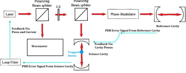
In order to do this, the lattice laser is split and sent along two paths. One path is compared to the stable reference cavity and one path is sent to the science cavity. Since the cavity resonances of the reference cavity don’t necessarily match the magic wavelength, an electrooptic modulator on the path to the reference cavity creates a sideband and adjustable distance from the main laser frequency that can be compared
to the cavity resonance mode.
Since the science cavity length is controlled by piezoelectrics, it changes relatively slowly. The laser, on the other hand, can adjust its frequency very quickly. Oscillations of the intensity of the optical lattice will heat atoms if they are twice the trapping frequency (≈ 490 kHz.) Since changes in laser frequency are converted into intensity fluctuations by the cavity, we need to suppress frequency fluctuations out to at least 500 kHz. On the other hand, tandem drift of the optical lattice and the science cavity is less detrimental, as it does not affect the dipole trap and will not cause Stark shift broadening large enough to quench the superradiance as long as the total frequency drift does not exceed ≈ 1 MHz. Since the drift between the science cavity and the laser needs to be controlled more tightly than the drift between the laser frequency and the magic wavelength, it makes sense to move the laser frequency to match the science cavity resonances and adjust the science cavity length to keep this resonance at the magic wavelength.
To achieve this, we use the PDH error signal generated from the reflected lattice laser at the science cavity to correct the laser frequency directly, locking the frequency of the laser to the resonance of the science cavity, and then use the PDH error from the lattice laser at the reference cavity to correct the science cavity length. There are two main negative feedback loops involved in the optical lattice system. One loop measures the frequency of the laser in relation to the science cavity with the PDH method and corrects by changing the optical feedback path piezo and the current to the laser. Another loop monitors the lattice laser frequency (now offset by some amount) relative to the reference cavity and corrects by adjusting the lengths of the science cavity with piezos.
3.1
Laser Diode and Optics Configuration
A Photodigm 760 nm distributed Bragg reflector diode laser produces the light for the optical lattice. This diode consists of a AlGaAs double well gain medium with a Fabry-Pérot cavity formed by two Bragg reflectors, one of which is partially transmissive.
Figure 3-1: The a schematic of the entire lattice trapping system.
The body of the laser also contains a thermoelectric cooling element for temperature control and a thermistor for measuring the diode temperature. 1
The light leaves the laser diode traveling at a broad range of solid angles. A collimating lens, held at a fixed distance from the laser by optics rails, focuses this into a collimated beam. Because the laser gain medium is horizontally wide but vertically narrow, the laser far field, which is essentially a Fourier transform of the intensity profile at the output of the laser chip, is wider in one direction than the other. In order to match this beam to the symmetric Gaussian profile of a fiber mode, we use an anamorphic prism pair to narrow the broader dimension of the collimated laser beam without changing its curvature.
A beam splitter splits off some of the collimated, symmetric beam for optical feedback. After the beam splitter, the laser passes through an isolator which attenuates any light passing through it in the wrong direction by 60dB, blocking any back reflections that might make the laser unstable. After the isolator, the laser beam passes through a half-wave plate and polarization beam splitter. The PBS ensures the laser light that is coupled into the output fiber is purely linearly polarized and matches with one of the axes of the polarization preserving fiber. The half wave plate allows adjustment of the laser output power. Finally the laser beam is coupled into a 1[31] is an excellent reference for all parts of the construction and frequency stabilization of diode
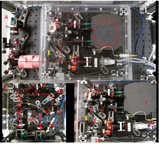
Figure 3-2: Pane A: The lattice laser enclosure: 1 is a fiber coupler which couples the laser into a fiber that runs to the splitting station. 2 is a polarizing beam splitter (PBS) that guarantees the laser polarization is along one of the axes of the polarization preserving fiber. 3 is a half wave plate which, along with the PBS, allows adjustment of output power. 5 is an optical isolator that uses Faraday rotation.
Pane B: The splitting station: 1 is a fiber coupler. 2 and 3 and 4 and 5 are pairs
of half wave plates and PBS that allow adjustable splitting of the laser power. 6,7,8 and 9,10,13 are half wave plate, mirror, and fiber coupler combinations which send light to the reference cavity and wavemeter. 14 is an AOM that allows rapid on-off switching of light sent to the cavity. 16 is the EOM for the reference cavity PDH lock.
Pane C: Close up of the inner lattice laser enclosure: 1 is the laser and collimating
lens. 2 is the anamorphic prism pair. 3 is a 90-10 beam splitter for the optical feedback. 10 is a photodiode to measure the power of the optical feedback. 4 is a PBS to guarantee the light is polarized along an axis of the polarization maintaining fiber. 5 is an iris to minimize back reflection from the fiber coupler, 6. 7 is the foam encasing the feedback fiber. 9 is the piezo actuated feedback mirror. 11 is the RF input to the laser. At far left is a RF low pass filter.
polarization-preserving, single-mode fiber.
This entire laser structure is mounted on a half-inch thick aluminum optics bread-board which sits on a layer of sorbothane rubber on the main experimental optics table. The laser breadboard is enclosed in a nearly air-tight acrylic box which is mounted on the optics table and has no contact with the laser breadboard. The acrylic box prevents air currents and sound waves from perturbing the laser. The cables that supply the laser current, TEC current and piezo voltage as well as the fiber optic that carries the laser light out all pass through a small hole in the acrylic box. All of the cables pass through a strain reliever both inside and before entering the box, reflecting vibrations they may be carrying.
For further vibration isolation, all parts to the laser prior to the optical isolator are mounted on another aluminum breadboard inside the laser box. This breadboard has another layer of sorbothane under it and another acrylic box around it to further isolate it from noise. Finally, the feedback fiber is coiled inside a block of packing foam to further isolate it from vibration.
The laser travels through the output fiber to the splitting station, shown in Pane B of figure 3-2, where the light is split and sent to the science cavity, reference cavity, and wavemeter. The splitting is done with two pairs of polarizing beam splitters and half wave plates. This allows the power splitting to be adjusted. Like the laser itself, the splitting station is mounted on a half inch aluminum breadboard which rests on a sorbothane pad. The entire splitting station is enclosed in an acrylic housing.
The optical path to the science cavity passes through an acousto-optic modulator (AOM) which allows fast on-off switching of the light to the cavity. The output fiber is aligned so that light from the first order mode of the AOM is coupled. This means that light only reaches the science cavity when RF is applied to the AOM. An 80 MHz signal for the AOM is produced by an AD9959 direct digital synthesizer and amplified to 20dBm by RF amplifiers. By carefully adjusting the angle of the AOM and the RF power supplied, I achieve 80% coupling efficiency of the first order mode.
The optical path to the reference cavity passes through an EOM which is used to create the offset frequency between the science and reference cavities as well as
the sidebands for the PDH lock. The EOM is mounted inside the splitting station to reduce the fiber length between the PBS and the EOM. This is beneficial because the performance of the EOM depends heavily on the purity of polarization of incoming light. Although the PBS isolates exactly linear polarization and the EOM input fiber is polarization preserving, vibration of the fiber can rotate the polarization, degrading the EOM performance.
3.2
Output Coupling
To efficiently couple light from the laser diode to the output fiber, I carefully chose the positions of the collimating lens, the anamorphic prism pair, and the optical isolator. To choose the position of the collimating lens, I placed a beam profiler in the far field of the laser (approximately 30 mm from the end facet) and observed the beam profile in real time as I adjusted the lens position. I adjusted the lens position for the smallest possible beam size while also minimizing diffraction peaks. In the end, I was able to achieve a beam size of 0.5 mm with only a first order diffraction peak, probably due to insufficient numerical aperture of the collimating lens in the wider beam dimension.
Following a similar procedure, I carefully adjusted the position of the anamorphic prism pair while observing the beam profile. I adjusted the position and angle of the APP to make the dimensions of the beam equal to each other, while trying to minimize diffraction peaks. While I was able to make the dimensions of the beam equal overall, some asymmetry remained, probably due to the asymmetric geometry of the laser diode end facet.
Finally, I adjusted the optical isolator while measuring the power of the beam. After I had optimized for maximum beam power, I measured the beam profile. The isolator blocked the extra diffraction peaks of the beam, leaving a mostly Gaussian profile. The laser diode to output fiber coupling efficiency was 45%, comparable to other diode lasers in our lab.
Figure 3-3: Lattice laser beam profiles with distances in microns. The beam profile before the collimator is very broad, as the laser is diverging rapidly from the small end facet. The laser profile after the collimating lens is narrower, but still much broader in one dimension than the other. The anamorphic prism pair corrects the difference in dimensions at the cost of some small diffraction fringes. The narrow isolator blocks these additional fringes, making the profile symmetric and Gaussian.
3.3
Intrinsic Linewidth
A laser’s frequency can vary over a wide variety of timescales. Very fast variation (i.e. faster than the relevant time scale, in this case, the residence time of light in the science cavity) contributes to the laser’s linewidth. Frequency variation slower than the cavity residence time manifests as jitter - drift of the laser frequency. Another way of putting this is that the laser frequency rapidly varying over a range of frequencies is equivalent to the laser emitting all frequencies in the range simultaneously.
One way to quantify the variation in the laser’s frequency is with the frequency spectral noise density, defined by the Fourier transform of the auto-correlation function of its frequency.
𝑆𝜈(𝜔) = ∫︁
𝑑𝜏 𝑒𝑖𝜔𝜏Γ𝜈(𝜏)
Γ𝜈(𝜏) = ⟨𝜈(t)𝜈(t − 𝜏)⟩
to the side of a transmission fringe of a low finesse cavity with a very low bandwidth feedback loop. Since the bandwidth of the lock is low, the spectral noise density is only affected at very low frequencies. Meanwhile, the transmission function of the low finesse cavity, effectively converts frequency fluctuations into amplitude fluctuations, which can then be measured by a photodiode.
To measure the free-running spectral noise density of the lattice laser, I locked a Thorlabs SA200 Fabry-Pérot cavity, which has a finesse of roughly 200, to the laser. For my feedback actuator, I used the piezo-adjustable cavity, with a feedback bandwidth of 10 Hz. The resulting power fluctuations of the light transmission were measured with a DC-coupled APD with a bandwidth of 20MHz and fed into a spectrum analyzer. The resulting spectrum is shown in figure 3-4.
To keep the laser’s frequency equal to the cavity resonance frequency, we can compare the laser frequency to the resonance of the cavity and use electronic feedback to correct the laser’s frequency. The maximum speed at which the feedback can correct the laser determines the bandwidth of frequencies over which the feedback works. If the feedback bandwidth is less than the cavity finesse, the laser’s linewidth will not be modified, but laser jitter will be suppressed and the laser frequency will be centered at the cavity resonance. If the feedback bandwidth is greater than the interaction frequency, then the linewidth of the laser will be narrowed. Greater feedback bandwidth leads to smaller linewidth until the bandwidth reaches a saturation frequency 𝑓𝑐≈1.78ℎ0 determined by the intrinsic level of noise in the laser ℎ0. At this
point the feedback has narrowed the laser linewidth as much as possible and mechanical noise in the reference cavity is the primary contributor to the laser linewidth.
The linewidth of the Photodigm laser is 3 MHz in the absence of feedback. There-fore, to narrow the linewidth of the laser we would need electronic feedback with a bandwidth of at least 3 MHz. This poses several technical challenges. The first is that the active electronics that don’t add phase delay above 1 MHz are expensive and complicated. The bigger challenge, however, is that the effect of laser diode current modulation changes past 1 MHz. At lower frequencies, additional injection current heats the laser diode, causing the gain medium to expand slightly and increasing the
Figure 3-4: Optical feedback in Regime 3 suppresses the phase noise of the laser at frequencies above the FSR of the optical feedback path.
wavelength of emitted light. At higher frequencies, injected current does not have time to heat the diode, so the primary mechanism of action is an increase in the index of refraction caused by higher electron density. This causes the emitted wavelength to be shorter. It is difficult to design feedback around these conflicting effects.
3.4
Optical Feedback
Fortunately, we can use optical feedback to narrow the laser’s linewidth to 1 MHz and simplify the design of the electrical feedback [32]. To remove the higher frequency noise, we use a technique known as optical feedback. Inserting a beam splitter in the laser’s path we split off some of the light and send it down and optical fiber. At the end of the optical fiber the light is reflected back along the same path by a mirror whose position can be changed very precisely by a piezoelectric stack. This light then reenters the laser. The photons of the returning beam, which were emitted hundreds of nanoseconds prior, stimulate more emission in the laser’s gain medium. These returning photons guarantee that the laser will emit a frequency very close to the one it was emitting hundreds if nanoseconds ago.

![Figure 2-1: Spontaneous emission of photons causes phase diffusion in the laser [11].](https://thumb-eu.123doks.com/thumbv2/123doknet/14207969.481367/25.918.308.615.111.405/figure-spontaneous-emission-photons-causes-phase-diffusion-laser.webp)
![Figure 2-2: Dicke states [23]. The superradiant lasing transitions are the tranisitions between the latter of states where L=N/2.](https://thumb-eu.123doks.com/thumbv2/123doknet/14207969.481367/31.918.138.777.107.403/figure-dicke-states-superradiant-lasing-transitions-tranisitions-states.webp)