Publisher’s version / Version de l'éditeur:
Vous avez des questions? Nous pouvons vous aider. Pour communiquer directement avec un auteur, consultez la
première page de la revue dans laquelle son article a été publié afin de trouver ses coordonnées. Si vous n’arrivez pas à les repérer, communiquez avec nous à [email protected].
Questions? Contact the NRC Publications Archive team at
[email protected]. If you wish to email the authors directly, please see the first page of the publication for their contact information.
https://publications-cnrc.canada.ca/fra/droits
L’accès à ce site Web et l’utilisation de son contenu sont assujettis aux conditions présentées dans le site LISEZ CES CONDITIONS ATTENTIVEMENT AVANT D’UTILISER CE SITE WEB.
Internal Report (National Research Council of Canada. Institute for Research in
Construction), 1998-05-01
READ THESE TERMS AND CONDITIONS CAREFULLY BEFORE USING THIS WEBSITE.
https://nrc-publications.canada.ca/eng/copyright
NRC Publications Archive Record / Notice des Archives des publications du CNRC :
https://nrc-publications.canada.ca/eng/view/object/?id=785a34f5-1001-41a9-8e5f-53fb09b06c52 https://publications-cnrc.canada.ca/fra/voir/objet/?id=785a34f5-1001-41a9-8e5f-53fb09b06c52
NRC Publications Archive
Archives des publications du CNRC
For the publisher’s version, please access the DOI link below./ Pour consulter la version de l’éditeur, utilisez le lien DOI ci-dessous.
https://doi.org/10.4224/20331574
Access and use of this website and the material on it are subject to the Terms and Conditions set forth at
Results of Fire Resistance Tests on Full-Scale Floor Assemblies
Results of Fire Resistance Tests on Full-Scale Floor Assemblies
Sultan, M.A.; Séguin, Y.P.; Leroux, P.
IRC-IR-764
i
RESULTS OF FIRE RESISTANCE TESTS ON FULL-SCALE FLOOR ASSEMBLIES
by
M. A. Sultan, Y.P. Séguin and P. Leroux
ACKNOWLEDGEMENTS
The National Research Council of Canada wishes to acknowledge the technical and financial contributions of the partners in this Joint Research Project. The partners include:
• Boise Cascade
• Canada Mortgage and Housing Corporation
• Canadian Home Builders Association
• Canadian Portland Cement Association
• Canadian Sheet Steel Building Institute
• Canadian Wood Council
• Cellulose Insulation Manufacturers Association of Canada
• Forintek Canada Corporation
• Gypsum Association
• Gypsum Manufacturers of Canada
• Louisiana-Pacific Corporation
• Nascor Inc.
• Ontario New Home Warranty Program
• Ontario Ministry of Housing
• Owens-Corning Canada
• Roxul Inc.
• Trus Joist MacMillan
ii
RESULTS OF FIRE RESISTANCE TESTS ON FULL-SCALE FLOOR ASSEMBLIES
by
M. A. Sultan, Y.P. Séguin and P. Leroux
SUMMARY
This report presents the results of 32 standard fire resistance tests conducted on full-scale floor assemblies as part of the collaborative industry-government research program investigating the effects of subfloor material, gypsum board screw spacing from board edges, wood-I-joist type, method of fastening the gypsum board butt ends,
insulation type, joist type, number of gypsum board layers, joist spacing, resilient channel installation, resilient channel spacing, addition of concrete topping, steel/concrete
composite systems and structural load. The results of the full-scale tests showed that: 1. The type of subfloor (oriented strand board and plywood) did not affect the fire
resistance of the assembly.
2. An assembly with screws 38 mm from the gypsum board edges provided a significant increase in fire resistance compared to an assembly with screws at 10 mm from the gypsum board edges.
3. For non-insulated wood-I-joist assemblies, the joist flange configuration and size affected the fire resistance of the assembly. An assembly with flanges 64 mm wide by 38 mm deep provided 16% more fire resistance than an assembly with flanges 38 mm wide by 38 mm deep and 8% more than an assembly with flanges 38 mm wide by 64 mm deep.
4. The method of fastening the gypsum board face layer butt ends to the resilient channels in wood-I-joist assemblies with two layers of gypsum board affected the fire resistance. An assembly with Type G screws used to fasten the face layer to base layer at the butt ends provided 7% more fire resistance than an assembly with steel screws used to fasten the gypsum board face layer to the base layer and resilient channels.
5. Assemblies with fasteners at the butt ends provided 57% more fire resistance than the assembly without fasteners (floating butt ends).
6. For assemblies with solid wood joists and a single layer gypsum board ceiling finish, glass fibre insulation reduced the fire resistance by 20% while rock and cellulose fibre insulation increased the fire resistance by 33% and 31%, respectively,
compared to a non-insulated assembly. For assemblies with a double layer gypsum board ceiling finish, glass, rock and cellulose fibre insulation reduced the fire
resistance by 16%, 10% and 7.5%, respectively, compared to a non-insulated assembly.
7. For floor assemblies with wood-I-joists and a single layer gypsum board ceiling finish, rock fibre insulation increased the fire resistance by 10% while cellulose fibre insulation increased the fire resistance by 24% compared to a non-insulated
assembly. For assemblies with a double layer gypsum board ceiling finish, glass fibre insulation reduced the fire resistance by 7% and rock fibre insulation increased the fire resistance by 7% compared to a non-insulated assembly.
8. The installation of a second layer of gypsum board to a floor assembly with a single layer gypsum board ceiling finish increased the fire resistance by 77% for
iii
9. For wood-I-joist floor assemblies with glass fibre insulation and a double layer gypsum board ceiling finish, joist spacing (406 mm o.c. and 610 mm o.c.) affected the fire resistance. An assembly with 610 mm o.c. joist spacing provided 16% more fire resistance than an assembly with 406 mm o.c. spacing.
10. For wood-I-joist floor assemblies with glass fibre insulation and a double layer of gypsum board ceiling finish, resilient channel spacing (410 mm o.c. and 610 mm o.c.) affected the fire resistance. An assembly with 406 mm o.c. channel spacing provided 14% more fire resistance than an assembly with 610 mm o.c. spacing. 11. For floor assemblies with steel joists and a double layer gypsum board ceiling finish,
the installation of glass fibre in the floor cavity reduced the fire resistance by 8% compared to a non-insulated assembly.
12. For steel joist floor assemblies with glass fibre insulation and a double layer of gypsum board ceiling finish, joist spacing (406 mm o.c. and 610 mm o.c.) did not affect the fire resistance.
13. Adding concrete topping to an assembly with steel joists and a double layer of gypsum board ceiling finish reduced its fire resistance.
14. The structural load (75% and 100% of maximum design load) affected the fire resistance of solid wood joist assemblies.
15. A steel/concrete composite floor protected by two layers of gypsum board provided 105 min fire resistance.
1
RESULTS OF FIRE RESISTANCE TESTS ON FULL-SCALE FLOOR ASSEMBLIES
by
M. A. Sultan, Y.P. Séguin and P. Leroux
1.0 INTRODUCTION
In recent years, there have been a number of efforts to improve the quality of residential building environments in North America to meet public demands for better acoustic isolation. More stringent acoustic requirements were recently adopted in Canadian building codes and have necessitated changes in traditional construction practices. In addition, new construction materials have been developed and many construction practices and product specifications have changed over the past several years. Such changes may alter the fire resistance of floor assemblies. Consequently, there was a need to reaffirm existing fire resistance data for common floor constructions. This includes the information contained in Part 9, "Housing and Small Buildings",
Appendix A-9.10.3.1.B of the National Building Code of Canada (NBCC), 1995 Edition [1] which provides architects, building officials and fire protection engineers with simple detailed information on sound and fire resistance ratings for floor assemblies commonly used in the construction of housing in Canada.
In response to the changes noted above, the National Research Council of Canada (NRC), in collaboration with industry and government partners, carried out a research program to measure the acoustic and fire performance of floor assemblies. The objectives of this research is to reaffirm existing fire resistance ratings in the current NBCC and to develop cost-effective and innovative floor assemblies. This report
describes the results of the fire study. The results of the acoustic tests are presented in a separate NRC report [2].
This report presents the results of thirty-two full-scale fire resistance tests conducted at the Institute for Research in Construction (IRC), NRC, as part of the Joint Research Project on the fire and acoustical performance of floor assemblies. The parameters investigated in this fire study include:
• the subfloor material (oriented strand board (OSB) and plywood)
• gypsum board screw spacing from board edges (10 mm versus 38 mm)
• wood-I-joist type
• method of fastening the gypsum board butt ends (with and without screws)
• insulation type (glass, rock and cellulose fibre)
• joist type (solid wood, wood-I and steel)
• number of gypsum board layers, joist spacing (406 mm o.c. and 610 mm o.c.)
• resilient channel installation
• resilient channel spacing (406 mm o.c. and 610 mm o.c.)
• addition of concrete topping
• steel/concrete composite systems and
2
The floor assemblies tested are not exactly identical in every detail to those assemblies currently described in the NBCC [1]. Direct comparisons of the results to current listed assemblies are not possible in every case.
2.0 DESCRIPTION OF TEST ASSEMBLIES
Thirty-two full-scale test assemblies were constructed. Details on the assemblies are described below.
2.1 Dimensions
Thirty-two, 4840 mm long by 3950 mm wide, floor assemblies were constructed: fourteen with solid wood joists, twelve with wood-I-joists, five with C-steel joists and one composite steel deck/concrete assembly. The assemblies had various depths
depending on the number of gypsum board layers, joist depth and subfloor thickness. The specific dimensions are shown in Figures 1 to 96.
2.2 Materials
Materials used in the assemblies were as follows: 2.2.1 Ceiling Finish
Type X gypsum board, 12.7 mm and 15.9 mm thick, conforming to the requirements of CAN/CSA-A82.27-M91 [3], was used.
2.2.2 Framing
Three types of framing were used: solid wood joist, wood-I-joist and C-steel joist. The solid wood joists were nominal 2x10 (38 mm wide by 235 mm deep SPF S-Dry) conforming to CSA 0141-1970 [4]. The wood-I-joists were nominal 10 inches (240 mm deep) supplied by different partners. The different wood-I-joists used include: 38 mm wide by 38 mm deep laminated veneer lumber (LVL) flanges and 9.5 mm thick plywood web, 38 mm wide by 38 mm deep LVL flanges and 9.5 mm thick OSB web, 38 mm wide by 64 mm deep lumber flanges and 9.5 mm thick OSB web, 38 mm wide by 38 mm deep lumber flanges and 9.5 mm thick OSB web and 64 mm wide by 38 mm deep lumber flanges and 9.5 mm thick OSB web. The C-steel joists were nominal 2x8 (203 mm deep, 18 gauge) conforming to CAN/CGSB-7.1 [5].
2.2.3 Insulation
Three types of insulation were used: glass fibre batts, 90 mm thick; rock fibre batts, 90 mm thick; and cellulose fibre insulation sprayed wet, 59 mm to 122 mm thick. The glass, rock and cellulose insulation used satisfy CSA A101 [6], CAN/ULC S702 [7] and CGSB 51.60 [8], respectively.
3
2.2.4 Subfloor
Two subfloor materials were used: Canadian softwood plywood (CSP) tongue and groove, 15.9 mm and 19.0 mm thick and OSB tongue and groove, 15.9 mm thick. 2.2.5 Resilient Channels
The resilient channels used in the assemblies consisted of sections of 0.18 mm thick galvanized steel. The channels consisted of a 34 mm web and one flattened 18 mm flange lip.
2.2.6 Concrete
The concrete used had a 19 mm coarse aggregate and a density of 2406 kg/m3. The slump during the pouring of the concrete was 75 mm. The concrete strength was 25 MPa after 28 days.
2.3 Fabrication
Thirty-two floor assemblies, 3950 mm wide by 4840 mm long, were constructed: fourteen assemblies with solid wood joists, twelve with wood-I-joists, five with steel joists and one with composite steel deck/concrete. Details on these assemblies are given below. On some assemblies, the gypsum board ceiling finish was directly attached to the joists, with Type S drywall steel screws, 25 mm long. In other assemblies, the gypsum board was attached to resilient channels mounted perpendicular to the joists, with 32 mm long Type S steel screws for the base layer and 41 mm long Type S steel screws for the gypsum board face layer in accordance with CAN/CSA-A82.31-M91 [9] and input from the research partners. For some assemblies, Type G screws (38 mm long) were used in fastening the butt ends of the face layer of the gypsum board to the base layer.
2.3.1 Solid Wood Joist Floor Assemblies
Fourteen floor assemblies were constructed using solid wood joists: seven assemblies with a single layer of gypsum board (Assemblies No. NRC-01, No. FF-01, No. FF-01A, No. FF-02A, No. FF-07, No. FF-08 and No. FF-09) and seven assemblies with a double layer of gypsum board (Assemblies No. FF-03, No. FF-03A, No. FF-04A, No. FF-05, No. FF-06, No. FF-28 and No. FF-29). Details for these assemblies are given in Table 1.
The solid wood joist frames were constructed using nominal 2x10 joists spaced 406 mm o.c. with one row of wood cross bracing, 19 mm thick by 64 mm wide, placed at the centre of the assembly between the joists. Details on the joist layout are presented in Figure 1.
Two types of subfloor material were used: CSP plywood and OSB, 15.9 mm thick. The subfloor board was attached to the wood joists with common nails, 64 mm long around the perimeter of the assemblies and 51 mm long in the field. The board layout and nail pattern are shown in Figures 2 to 5.
4
The assemblies were constructed with and without the installation of resilient channels. Assemblies No. NRC-01, No. FF-01 and No. FF-01A had no resilient channels while Assemblies No. 02A, No. 03, No. 03A, No. 04A, No. 05, No. FF-06, No. FF-07, No. FF-08, No. FF-09, No. FF-28 and No. FF-29 had resilient channels attached perpendicular to the joists. For those assemblies with resilient channels, there was one arrangement of resilient channels for the assemblies with a single layer of gypsum board (Figure 6) and two arrangements of resilient channels for the assemblies with a double layer of gypsum board (Figures 7 and 8). For assemblies with a single layer of gypsum board, the arrangement of resilient channels was chosen to allow the gypsum board butt ends to be fastened to the resilient channels with screws 38 mm from the board edges. For assemblies with a double layer of gypsum board,
two arrangements of resilient channels were chosen to allow both the base and face layer butt ends to be fastened to the channels with screws either 25 mm or 38 mm from the board edges.
Assemblies No. NRC-01, No. 01, No. 01A, No. 02A, No. 07, No. FF-08 and No. FF-09 had a single layer of gypsum board ceiling finish while Assemblies No. FF-03, No. FF-03A, No. FF-04A, No. FF-05, No. FF-06, No. FF-28 and No. FF-29 had a double layer of gypsum board (base layer and face layer).
Two gypsum board thicknesses were used: 12.7 mm and 15.9 mm. The
thickness of the board for each assembly is given in Table 1. Details on the board layout, screw spacing and their locations from the board edge for assemblies with a single layer of gypsum board are shown in Figures 9 to 17. In double layer gypsum board
assemblies, the board joints for the face and base layers were staggered. Details on the gypsum board layout, screw spacing and locations from the board edge are shown in Figures 18 to 25.
In Assembly No. FF-03 with two gypsum board layers, the face layer butt end joints were centered between two rows of resilient channels and were not fastened to the gypsum board base layer (floating butt ends). Details on the board layout, screw spacing and locations are shown in Figures 18 to 21. In Assemblies No. FF-03A, No. FF-04A, No. FF-05, No. FF-06, No. FF-28 and No. FF-29, the face and base layer gypsum board butt end edges were attached to separate resilient channels with screws 38 mm from board edges. Details on the board layout, screw spacing and screw locations from the board edge are shown in Figures 22 to 25.
The assemblies were constructed with and without insulation in the floor cavity. For insulated assemblies, the insulation (glass or rock fibre batts) was placed above the resilient channels between the joists as shown in Figures 26 and 27. The cellulose fibre insulation was sprayed wet on the side of the joists and on the underside of the subfloor as shown in Figures 28 and 29.
2.3.2 Wood-I-Joist Floor Assemblies
Twelve floor assemblies were constructed using wood-I-joists: three assemblies with a single layer of gypsum board (Assemblies No. FF-14, No. FF-16 and No. FF-19) and nine assemblies with a double layer of gypsum board (Assemblies No. FF-10, No. FF-11, No. FF-12, No. FF-13, No. FF-15, No. NRC-02, No. FF-17, No. FF-18 and No. FF-20). Details on these assemblies are given in Table 1.
5
The wood-I-joist frames were constructed using 2x10 nominal (240 mm deep) joists spaced 406 mm o.c. and 610 mm o.c. Details on the joist layout are shown in Figures 30 and 31.
The subfloor material used was CSP plywood board, 15.9 mm thick for joists spaced at 406 mm o.c. and 19 mm thick for joists spaced at 610 mm o.c. The subfloor boards were attached to the wood-I-joist with glue (PL premium construction adhesive) and common nails, 64 mm long around the perimeter of the assemblies and 51 mm long in the field. The board layout and nail pattern are shown in Figures 32 to 35. Details on the wood-I-joist/end plate connections are shown in Figures 36 to 38.
The assemblies had resilient channels attached perpendicular to the joists spaced at 406 mm for all wood-I-joist assemblies except Assembly No. FF-20 in which the channels were spaced 610 mm o.c. There were five arrangements of resilient channels (see Figures 39 to 43) used for the double layer of gypsum board assemblies and one arrangement used for the single layer gypsum board assemblies (see
Figure 44). For assemblies with a double layer of gypsum board, the first arrangement of resilient channels (Figure 39) was chosen to allow the butt ends for both the base and face layers of gypsum board to be fastened to the channels spaced at 406 mm o.c. (wood-I-joists spaced at 406 mm o.c.) with screws 38 mm from the board butt edges. The second arrangement of resilient channels (Figure 40) was chosen to allow the butt ends of the gypsum board base layer to be fastened to the channels spaced at 406 mm o.c. (wood-I-joists spaced at 406 mm o.c.) with screws 38 mm from the board edges while the butt ends of the face layer were fastened to the base layer with Type G screws, 38 mm long. The third arrangement of resilient channels (Figure 41) was chosen to allow the butt ends of the gypsum board base layer to be fastened to the channels spaced at 406 mm o.c. (wood-I-joists spaced at 610 mm o.c.) with screws 38 mm from the board edges while the butt ends of the face layer were fastened to the base layer with Type G screws, 38 mm long. The fourth arrangement of resilient channels (Figure 42) was chosen to allow the butt ends of the gypsum board base layer to be fastened to the channels spaced at 406 mm o.c. (wood-I-joists spaced at 610 mm o.c.) with screws 10 mm from the board edges while the butt ends of the face layer were fastened to the base layer with Type G screws, 38 mm long. The fifth arrangement of resilient channels
(Figure 43) was chosen to allow the butt ends of the gypsum board base layer to be fastened to the resilient channels spaced at 610 mm o.c. (wood-I-joists spaced at 610 mm o.c.) with screws 10 mm from the board edges while the butt ends of the face layer were fastened to the base layer with Type G screws, 38 mm long. For assemblies with a single layer of gypsum board, the arrangement of resilient channels (Figure 44) was chosen to allow the butt ends of the gypsum board to be fastened to the channels
spaced at 406 mm o.c. (wood-I-joists spaced at 406 mm o.c.) with screws, 32 mm long, 38 mm from the board edges.
Assemblies No. FF-14, No. FF-16 and No. FF-19 had a single layer of gypsum board while Assemblies No. FF-10, No. FF-11, No. FF-12, No. FF-13, No. FF-15, No. NRC-02, No. FF-17, No. FF-18 and No. FF-20 had a double layer of gypsum board. The gypsum board thickness used in these assemblies was 12.7 mm thick. In the double layer gypsum board assemblies, the board joints for the face and base layers were staggered. Details on the gypsum board layout, screw spacing and locations for the single and double layer gypsum board assemblies are shown in Figures 45 to 67.
6
The assemblies were constructed with and without insulation in the floor cavity. For insulated assemblies (see Table 1), the insulation (glass or rock fibre batts) was placed above the resilient channels between the joists as shown in Figures 68, 69 and 70. The cellulose fibre insulation was sprayed wet on the side of the joists and on the underside of the subfloor as shown in Figure 71.
2.3.3 Steel Joist Floor Assemblies
Five floor assemblies were constructed using steel joists: one assembly with a single layer of gypsum board (Assembly No. FF-25) and four assemblies with a double layer of gypsum board (Assemblies No. FF-22, No. FF-23, No. FF-24 and No. FF-27). Details on these assemblies are given in Table 1.
The steel frames were constructed using nominal 2x8 joists (203 mm deep, 18 gauge) in Assemblies No. FF-22, No. FF-23, No. FF-24, No. FF-25 and No. FF-27). The steel joists were spaced 406 mm o.c. for all assemblies except Assembly No. FF-24 where the joists were spaced 610 mm o.c. Details on the joist layout are shown in Figures 72 and 73. Details on steel joist/end connections and blocking as well as track joints are shown in Figures 74 to 76.
The subfloor material used for the steel joist floor assemblies was tongue and groove CSP, 15.9 mm thick. The subfloor boards were attached to the steel joists with No. 10 bugle head steel screws, 32 mm long. The board layout and screw pattern are shown in Figures 77 and 78 for assemblies with the joists spaced at 406 mm o.c. and in Figures 79 and 80 for assemblies with the joists spaced at 610 mm o.c.
The assemblies constructed had resilient channels attached perpendicular to the joists spaced at 406 mm for all steel joist assemblies (see Figure 81) except for
Assembly No FF-24 where the joists were spaced 610 mm o.c. (see Figure 82). There were two resilient channel arrangements (Figures 81 and 82) used for the double layer gypsum board assemblies and one for the assembly with a single layer of gypsum board (Figure 83). For the assemblies with a double layer of gypsum board (joists spaced at 406 mm o.c. and at 610 mm o.c.), the resilient channel arrangements shown in
Figures 81 and 82 were chosen to allow the gypsum board base layer butt ends to be fastened to the resilient channels with screws 10 mm from the board edges. The butt ends of the face layer were centered between two rows of resilient channels and fastened to the base layer with Type G screws, 38 mm long. The resilient channel arrangement shown in Figure 83 was chosen to allow the gypsum board butt ends of the single layer of gypsum board to be fastened to the channels with screws 38 mm from the board edges.
Assemblies No. FF-22, No. FF-23, No. FF-24 and No. FF-27) had a double layer (base layer and face layer) of gypsum board as the ceiling finish, while Assembly No. FF-25 had a single layer of gypsum board. The gypsum board was 12.7 mm thick Type X. Details on the gypsum board layout, screw spacing and locations are shown in Figures 84 to 89. In the assemblies with two gypsum board layers, the gypsum board base layer butt ends were attached to the resilient channels with Type S screws, 3.2 mm long, and the face layer butt end joints were centered between two rows of resilient channels and were fastened to the gypsum board base layer with Type G screws, 38 mm long.
7
The assemblies were constructed with and without insulation in the floor cavity. For the insulated assemblies (see Table 1), the insulation (glass or rock fibre batts) was placed above the resilient channels between the joists as shown in Figures 90 to 93.
The construction details for Assembly No. FF-27 were similar to Assembly No. FF-23. In addition, regular concrete, 54 mm thick, was poured on the plywood subfloor. The assembly was stored for 30 days prior to the fire test. Details for this assembly are given in Table 1 and shown in Figure 93.
2.3.4 Steel/Concrete Composite Floor Assembly
Assembly No. FF-26 was constructed using corrugated steel deck , 0.91 mm thick. Regular weight concrete was poured on the deck as shown in Figures 94 and 95. Welded wire mesh, 152 mm by 152 mm and 3.8 mm diameter, was located inside the concrete (see Figure 95). The assembly was stored for three months for the concrete to cure.
After curing, resilient channels were attached perpendicular to the corrugated steel deck (see Figure 96) with 11 mm long pan head steel stud framing screws.
Two layers of gypsum board were attached to the resilient channels. The gypsum board layout and screw pattern are shown in Figures 84 to 87. The gypsum board base layer butt ends were attached to the resilient channels with Type S screws, 32 mm long, located 10 mm from the board edges as shown in Figure 85. The face layer butt end joints were centered between two rows of resilient channels and were fastened to the gypsum board base layer with Type G screws, 38 mm long, located 38 mm from the board edges as shown in Figure 87.
3.0 INSTRUMENTATION
Type K (20 gauge) chromel-alumel thermocouples, with a thickness of 0.91 mm, were used for measuring temperatures at a number of locations throughout each
assembly. The thermocouple locations inside the test assemblies are documented in References 10 to 12. Nine thermocouples were installed on the unexposed surface to measure the unexposed surface temperature for each assembly. The thermocouple locations on the unexposed surface are shown in Figure 97.
The floor deflection was measured by nine deflection gauges connected by wires to the unexposed surface at the locations shown in Figures 98 and 99. The deflections were recorded using the electro-mechanical method described in Reference 13.
8
4.0 LOADING SYSTEM
The loading device consisted of a steel frame with thirty hydraulics jacks. Each jack transferred the load to the specimen through three circular steel pads, 178 mm in diameter and 12.7 mm thick. The loading arrangement is shown in Figure 100. Details on the loading system are presented in Reference 14. The loading frame was attached to the test assembly frame as shown in Figures 101 and 102.
The live load used for each assembly was provided to NRC by the partners. The load used for each assembly is given in Table 1. The load for the solid wood joist assemblies was determined using the L/360 deflection criterion, where L is the joist length, except for Assemblies No. FF-28 and No. FF-29. For these assemblies, the load was determined using the bending criterion (100% maximum strength load).
The loads for some wood-I-joist assemblies were determined using the
L/360 deflection criterion [No. FF-11 (94% maximum strength); No. FF-15 and No. FF-19 (74% maximum strength); No. FF-14 and No. FF-17 (93% maximum strength)]. The loads for Assemblies No. FF-10, No. FF-12, No. FF-13, No. FF-16, No. FF-18 and No. FF-20 were determined using the bending criterion (100% maximum strength).
The loads for steel joists assemblies were determined using the bending criterion (100% maximum strength).
5.0 TEST APPARATUS
The floor tests were carried out by exposing the assemblies to heat using the propane-fire horizontal furnace shown in Figures 101 and 102. Details on the furnace are given in Reference [14]. Each assembly was sealed at the edges against the furnace using ceramic fibre blankets. The furnace temperature was measured by nine (20 gauge) shielded thermocouples in accordance to CAN/ULC-S101-M89 [15]. The average of the nine thermocouple temperatures was used to control the furnace temperature.
Three video cameras were used to record the test observations; two of which viewed the fire-exposed surface from the East and West ends of the furnace while the other viewed the unexposed surface.
6.0 TEST CONDITIONS AND PROCEDURE
6.1 Fire Exposure
The floor assemblies were exposed to heat in such a way that the average temperature of the floor furnace, recorded by 9 thermocouples located 305 mm below the exposed surface of the sample, followed as closely as possible the CAN/ULC-S101-M89 [15] standard time-temperature curve. This time-temperature curve is similar to the ASTM E119 [16] time-temperature curve.
9
6.2 Failure Criteria
The failure criteria were derived from CAN/ULC-S101-M89 [15]. The assembly was considered to have failed if a single point temperature reading measured by one of the nine thermocouples under the insulation (see Figure 97) rose 180°C above the ambient temperature or the average temperature measured by the 9 thermocouples under insulating pads on the unexposed surface rose 140°C above the ambient
temperature or there was passage of flame or gases hot enough to ignite cotton waste.
7.0 RECORDING OF RESULTS
The temperatures of the furnace and floor assemblies were recorded at 1 minute intervals using Labtech Notebook* data acquisition software and Fluke Helios-I* data acquisition system. The temperature measurements inside the test assemblies and the average furnace temperature as well as the deflection measurements are given in References 8 to 10.
The average temperatures for the solid wood joist assemblies with a single layer of gypsum board were measured at the surface between the gypsum board and wood joists (SL/WJ), the gypsum board surface facing the cavity (SL/Cav), the joist mid-height (Mid. Jst), the subfloor surface facing the cavity (SF/Cav) and the surface between subfloor and joists (SF/WJ).
The average temperatures for the solid wood joist assemblies with a double layer of gypsum board were measured at the surface between the gypsum board face layer and the base layer under the wood joists (FL/WJ), the surface between the gypsum board face layer and the base layer under the cavity (FL/Cav), the joist mid-height (Mid. Jst), the surface between the base layer and the wood joists (BL/WJ), the gypsum board surface facing the cavity (BL/Cav), the subfloor surface facing the cavity (SF/Cav) and the surface between the subfloor and the joists (SF/WJ).
The average temperatures for the wood-I-joist assemblies with a single layer of gypsum board were measured at the surface between the gypsum board and wood-I-joists (SL/WIJ), the gypsum board surface facing the cavity (SL/Cav), the joist mid-height (Mid. Jst), the subfloor surface facing the cavity (SF/Cav) and the surface between the subfloor and the wood-I-joists (SF/WIJ).
The average temperatures for the wood-I-joist assemblies with a double layer of gypsum board were measured at the surface between the gypsum board face layer and the base layer under the wood joists (FL/WIJ), the surface between the gypsum board face layer and the base layer under the cavity (FL/Cav), the joist mid-height (Mid. Jst), the surface between the base layer and the wood-I-joists (BL/WIJ), the gypsum board
surface facing the cavity (BL/Cav), the subfloor surface facing the cavity (SF/Cav) and the surface between the subfloor and the wood-I-joists (SF/WIJ).
* Certain commercial products are identified in this report in order to adequately specify the experimental procedure. In no case does such identification imply recommendations or endorsement by the National Research Council, nor does it imply that the product or material identified is the best available for the purpose.
10
The average temperatures for the steel joist assemblies with a single layer of gypsum board were measured at the surface between the gypsum board and the steel joists (SL/SJ), the gypsum board surface facing the cavity (SL/Cav), the joist mid-height (Mid. Jst), the subfloor surface facing the cavity (SF/Cav) and the surface between the subfloor and the steel joists (SF/SJ).
The average temperatures for the steel joist assemblies with a double layer of gypsum board were measured at the surface between the gypsum board face layer and the base layer under the wood joists (FL/SJ), the surface between the gypsum board face layer and the base layer under the cavity (FL/Cav), the joist mid-height (Mid. Jst), the surface between the base layer and the steel joists (BL/SJ), the gypsum board surface facing the cavity (BL/Cav), the subfloor surface facing the cavity (SF/Cav) and the surface between the subfloor and the steel joists (SF/SJ).
8.0 RESULTS AND DISCUSSION
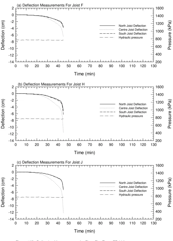
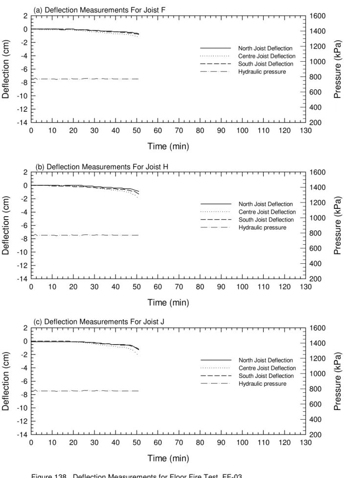
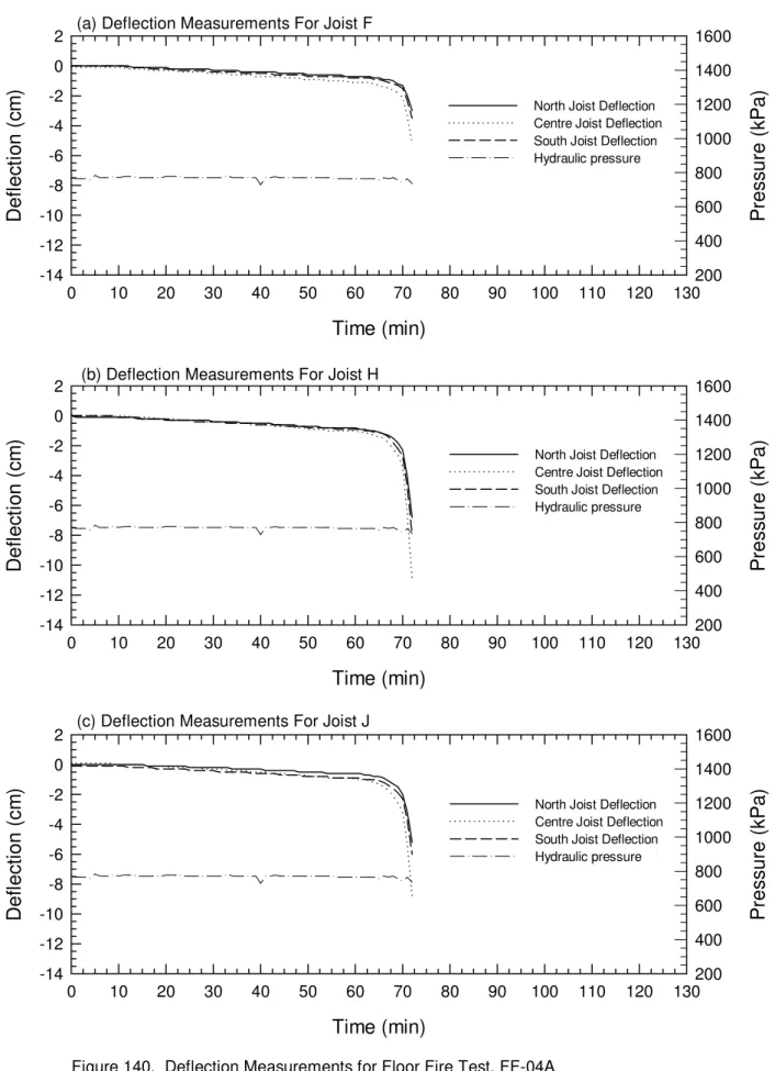
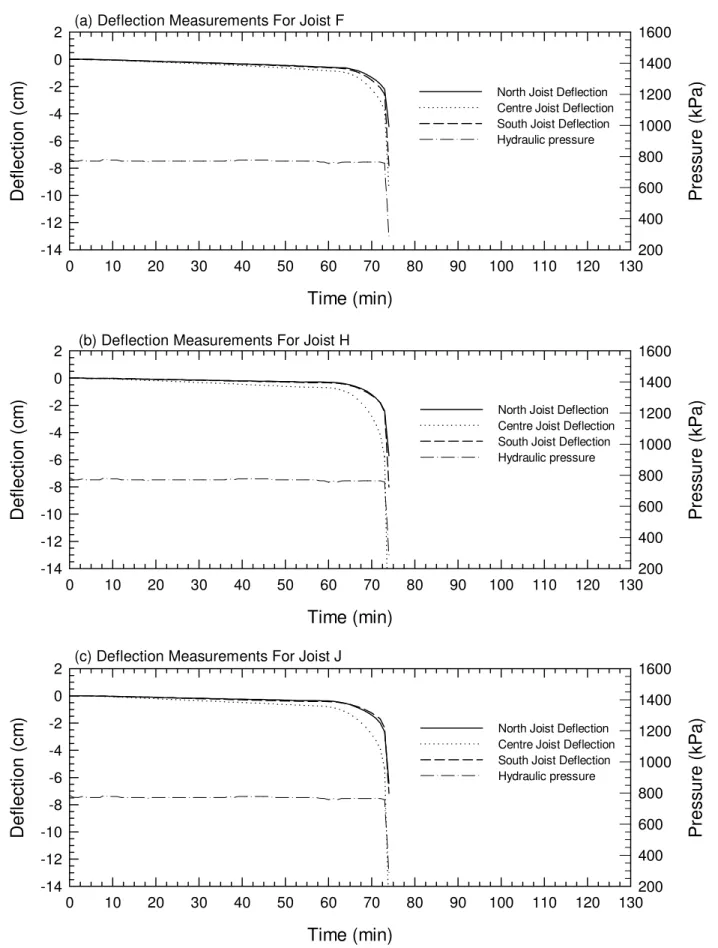
The results of the thirty-two full-scale fire resistance floor tests are summarized in Table 1 in which the fire resistance and mode of failure are given for each assembly. The average temperatures at different surfaces in each assembly and furnace average temperatures (Furnace Temp) as well as the unexposed surface temperatures (unExp) for the assemblies tested are plotted in Figures 103 to 134. The deflection
measurements for all assemblies tested are plotted in Figures 135 to 165. The effects of different parameters on the fire resistance of floor assemblies are discussed below.
8.1 Effect of Subfloor Type
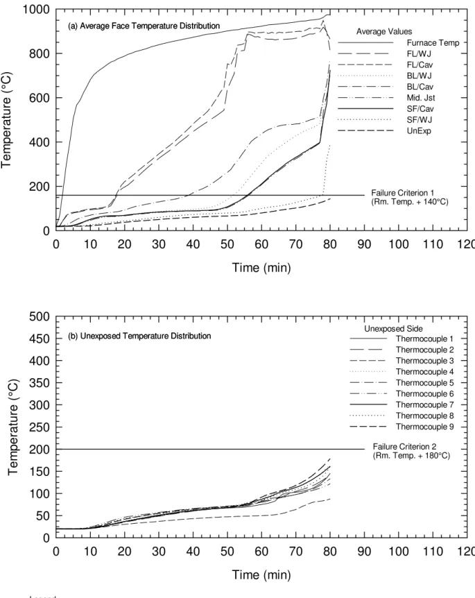
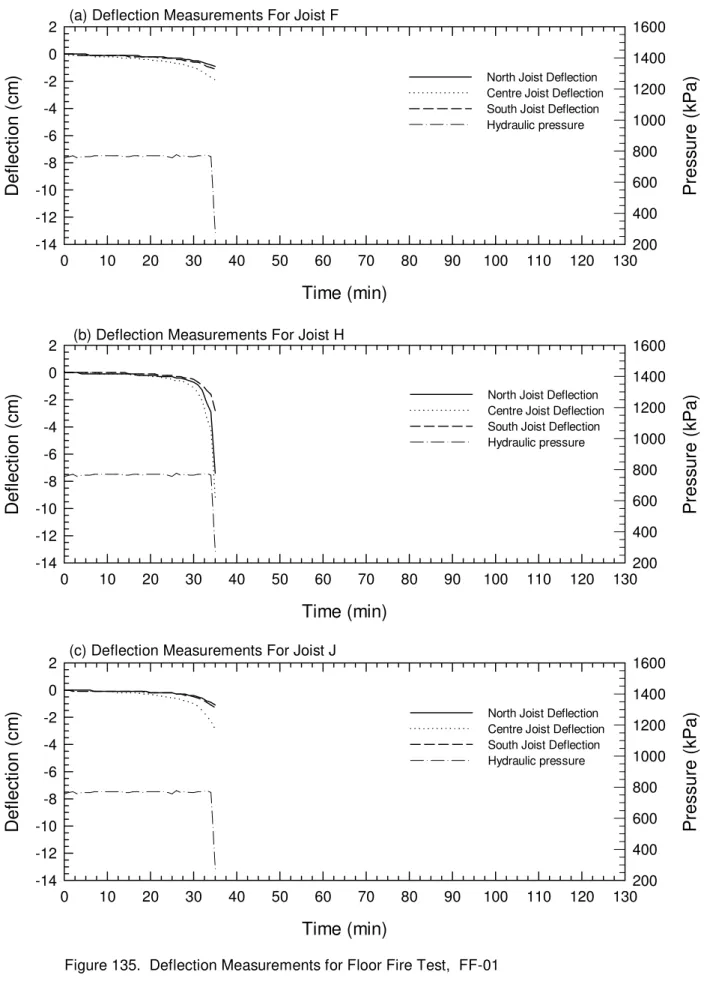
Assemblies No. NRC-01 (plywood) and No. FF-01 (OSB) were tested to investigate the effect of the subfloor type on the fire resistance of the assembly. Assembly No. NRC-01 provided 33 min fire resistance while Assembly No. FF-01 provided 35 min fire resistance.
The failure mode in both tests was flame penetration through the subfloor. These assemblies were tested with different live loads. However, because the failure mode was flame penetration, it was assumed that the load was not a governing factor in the fire resistance performance of these assemblies.
There is a difference in the fire resistance of the two assemblies. The gypsum board fell off at 28 min in Assembly No. NRC-01 and at 30 min in Assembly No. FF-01. The temperature distributions shown in Figures 109 and 110 indicate that the time difference between when the gypsum board fell off and flame penetration at the unexposed surface was approximately 5 min in both assemblies. Therefore, the difference in the fire resistance of the two assemblies was due to the difference in the performance of the gypsum board and thus, the effect of the subfloor type on the fire resistance was considered insignificant.
8.2 Effect of Gypsum Board Screw Spacing from Board Edges
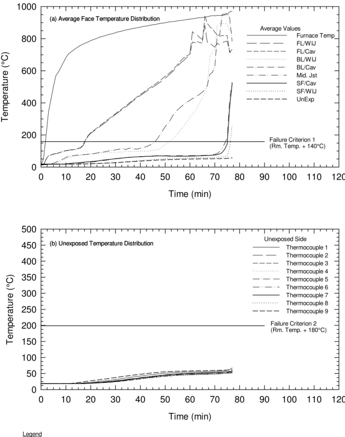
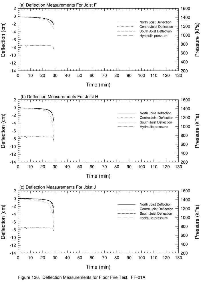
Floor Assemblies No. FF-01A and No. FF-02A were tested to investigate the effect of gypsum board screw spacing (10 mm versus 38 mm , respectively, from the board edges) on the fire resistance of a floor assembly with a single layer of gypsum
11
board ceiling finish. Assembly No. FF-01A provided a 30 min fire resistance while Assembly No. FF-02A provided 45 min. These results showed that, by moving the screws away from the board edges (from 10 mm to 38 mm), the fire resistance increased by 50%.
There are two factors which affected the fire performance of the gypsum board edges. First, the gypsum board core in the vicinity of the screw heads calcined faster than in the field of the board due to rapid heat transfer by the steel screws to the gypsum core around them. Second, the gypsum board core had less free and crystallized water at the board edges than in the field of the board due to the drying process during
manufacturing. The board, therefore, shrank faster at the edges than in the field of the board. These combined effects (shrinking at the edges and heating by the screws) caused the edges of the board to pull away earlier from the joists in the assembly with the screws 10 mm from the board edges. This accelerated the burning of the joists and subfloor and caused the assembly to fail earlier. The temperature distributions in Figures 105 and 106 indicate that the gypsum board fell off at 25 min in Assembly No. FF-01A and at 41 min in Assembly No. FF-02A.
8.3 Effect of Wood-I-Joist Type
Assemblies No. FF-10 to No. FF-12 with two layers of gypsum board as a ceiling finish and without insulation in the floor cavity were tested to investigate the effect of three wood-I-joist types (made by different manufacturers) on the fire resistance of the
assembly. Assembly No. FF-10 (wood-I-joists, with 38 mm wide by 38 mm deep LVL flanges and 9.5 mm thick plywood web) provided a 69 min fire resistance. Assembly No. FF-11 (wood-I-joists, with 38 mm wide by 64 mm deep lumber flanges and 9.5 mm thick OSB web) provided a 74 min fire resistance. Assembly No. FF-12 (wood-I-joists, with 64 mm wide by 38 mm deep lumber flanges) provided an 80 min fire resistance. These results showed that the type of wood-I-joists had an effect on the fire resistance of the assembly.
The average temperature distribution at different surfaces inside the assembly (see Figures 115 to 117) are more or less similar for three assemblies. However, the deflections at the centre joist of the assemblies were different as shown in Figures 146 to 148. Assembly No. FF-10 had more rapid deflection at the centre than Assemblies No. FF-11 and No. FF-12 after 60 min and Assembly No. FF-11 had more deflection than Assembly No. FF-12. This may indicate that the difference in the fire resistance is due to the differences in the flange geometry and size.
8.4 Effect of Method of Fastening the Gypsum Board Face Layer Butt Ends to
the Gypsum Board Base Layer
Assemblies No. FF-03 (no fasteners at the gypsum board face layer butt ends, floating butt ends) and No. FF-03A (with fasteners at the gypsum board face layer butt ends) were tested to investigate the effect of fasteners at the gypsum board butt ends (floating butt ends) on the fire resistance of the assembly. Assembly No. FF-03 (without fasteners) provided 51 min fire resistance while Assembly No. FF-03A (with fasteners) provided 80 min. These results showed that, by fastening the butt ends of the face layer, the fire resistance was increased by 57%.
12
Assemblies No. FF-10 (gypsum board face layer butt ends fastened to both the base layer and resilient channels with self-drilling steel screws) and No. FF-13 (gypsum board face layer butt ends fastened to the base layer with Type G screws) were tested to investigate the effect of fastening method of the butt ends face layer to the base layer of the gypsum board. Assembly No. FF-10 provided 69 min fire resistance while assembly No. FF-13 provided 74 min fire resistance. The gypsum board in the assembly with Type G screws remained in place longer and protected the joists (see the temperature distributions in Figures 115 and 118 and the deflection distributions in Figures 146 and 149). These results showed that the method of fastening the gypsum board face layer butt ends to the base layer had an effect on the fire resistance of the assembly.
8.5 Effect of Insulation Type
The effect of insulation type (glass, rock and cellulose fibre) on the fire resistance of floor assemblies with solid wood, wood-I and steel joists are given below.
8.5.1 Floor Assemblies with Solid Wood Joists
Floor Assemblies No. FF-02A (no insulation), No. FF-07 (cellulose fibre),
No. FF-08 (glass fibre) and No. FF-09 (rock fibre) were tested to investigate the effect of insulation type in the floor cavity on the fire resistance performance of floor assemblies with a single gypsum board ceiling finish. The fire resistances of these assemblies are given in Table 1. The temperature distributions inside the assembly and on the
unexposed surface for these assemblies are shown in Figures 106, and 112 to 114. Also, the deflection distribution for the these assemblies are shown in Figures 137 and 143 to 145. The results showed that the installation of the glass fibre insulation in the floor cavity reduced the fire resistance by 20% while the rock and cellulose fibre
increased the fire resistance by 33% and 31%, respectively, compared to a non-insulated assembly.
For the assembly with glass fibre insulation, the negative effect in the fire
resistance is due to the reduction in the heat transfer from the gypsum board to the cavity as shown by the rapid temperature rise on the gypsum board surface facing cavity (SL/Cav) in Figure 113 as compared to the temperature rise in the assembly with no insulation in Figure 106. This caused the gypsum board to calcine faster and fail earlier than in the non-insulated assembly. Also, the glass fibre melted within 2 to 3 min after the gypsum board fell off and was unable to compensate for the early failure of the gypsum board.
For the assemblies with rock and cellulose fibre insulation, there was also a rapid temperature increase on the gypsum board surface facing the cavity compared to the non-insulated assembly. This temperature rise caused the gypsum board to fail earlier in the insulated assemblies. However, the rock and cellulose fibre insulations remained in place after the gypsum board fell off and were able to compensate for the early failure of the gypsum board and protected the wood joists and subfloor for a substantial period.
Floor assemblies No. FF-03A, No. FF-04A, No. FF-05 and No. FF-06 were tested to investigate the effect of the installation of glass, rock and cellulose fibre in the floor cavity on the fire resistance performance of floor assemblies with a double layer of gypsum board ceiling finish. The fire resistance results for these assemblies are given in
13
Table 1. The results showed that the installation of insulation in the floor cavity of the assembly with a double layer of gypsum board reduced the fire resistance by 16% for an assembly with glass fibre insulation, by 10% for an assembly with rock fibre insulation and by 7.5% for an assembly with cellulose fibre insulation compared to an assembly with no insulation in the floor cavity.
In an insulated assembly, with two layers of gypsum board ceiling finish, the time during which the insulation was heated by conductive heat through the gypsum board was much longer than in an insulated assembly with a single layer of gypsum board. Also, the insulation caused the base layer of gypsum board to fail 10 to 20 min earlier (see Figures 108 to 111) than in a non-insulated assembly. The combined effects of insulation deterioration and early failure of the gypsum board resulted in a negative effect on the fire resistance compared to a non-insulated assembly.
8.5.2 Floor Assemblies with Wood-I-Joists
Floor assemblies No. FF-14, No. FF-16 and No. FF-19 were tested to investigate the effect of insulation (rock and cellulose fibre) in the floor cavity on the fire resistance performance of wood-I-joist floor assemblies with a single layer gypsum board ceiling finish. The fire resistance results for these assemblies are given in Table 1. The
installation of insulation in the floor cavity of an assembly increased the fire resistance by 10% for an assembly with rock fibre insulation and by 24% for an assembly with cellulose fibre insulation compared to an assembly with no insulation in the floor cavity.
In assemblies with wood-I-joists, rock and cellulose fibre insulations, there was a rapid increase in temperature on the gypsum board surface facing the cavity compared to that measured for a non-insulated assembly (see Figures 119, 121 and 125). A similar result was obtained for the solid wood joist assemblies. This more rapid temperature rise caused the gypsum board to fail earlier in the insulated assemblies. Both insulations (rock and cellulose fibre) remained in place after the gypsum board fell off and were able to compensate for the early failure of the gypsum board and protected the wood-I-joists and subfloor for a few minutes and, thus, provided a positive effect on fire resistance.
Floor assemblies No. FF-10, No. FF-15 and No. NRC-02 were tested to investigate the effect of the installation of insulation (glass and rock fibre) in the floor cavity on the fire resistance performance of wood-I-joist floor assemblies with a double layer gypsum board ceiling finish. The fire resistance results for these assemblies are given in Table 1. The results showed that the installation of insulation in the floor cavity of the assembly reduced the fire resistance by 7% for an assembly with glass fibre
insulation and increased the fire resistance by 7% for an assembly with rock fibre insulation compared to an assembly with no insulation in the floor cavity.
The glass fibre insulation reduced the fire resistance for this assembly similar to the solid wood joist assembly. The rock fibre insulation increased the fire resistance, unlike the assembly with solid wood joists where rock fibre insulation reduced the fire resistance. This was the result of different failure mechanisms for the two assemblies. The solid wood joist assembly failed by flame penetration through the subfloor while the wood-I-joist assembly failed structurally as fire-attacked the joist web reducing their ability to carry the load. The positive effect of the rock fibre insulation for the wood-I-joist
14
cavity. This is shown by the reduced deflection of the assembly during most of the test (see Figure 151) compared to the deflection measured for the non-insulated assembly (see Figure 146).
8.5.3 Floor Assemblies with Steel Joists
Floor assemblies No. FF-22 (no insulation) and No. FF-23 (glass fibre insulation) were tested to investigate the effect of the installation of insulation in the floor cavity on the fire resistance performance of steel joist floor assemblies with double layer gypsum board ceiling finish. The test results given in Table 1 showed that, like the assemblies with solid wood joists and wood-I-joists, the installation of glass fibre insulation in the floor cavity reduced the fire resistance by 8% compared to an assembly with no insulation in the floor cavity. This negative effect on the fire resistance is due to a reduction in the heat transfer from the gypsum board to the cavity, which increased the temperature of the gypsum board surface facing the cavity compared to a non-insulated assembly (see temperature distributions, BL/Cav, in Figures 127 and 128). This increase in gypsum board temperature caused the gypsum board to calcine faster and fall off earlier.
8.6 Effect of Number of Gypsum Board Layers
The effects of the number of gypsum board layers (single layer versus double layer) on the fire resistance of floor assemblies with solid wood and wood-I joists and no insulation in the floor cavity are given below.
8.6.1 Floor Assemblies with Solid Wood Joists
Floor Assemblies No. FF-02A and No. FF-03A were tested to investigate the effect of the number of gypsum board layers on the fire resistance of solid wood joist assemblies. The fire resistances given in Table 1, showed that the assembly with a double layer gypsum board ceiling finish provided an increase in the fire resistance by 78% compared to an assembly with a single layer gypsum board. The additional layer of gypsum board provided longer fire protection to the joists and this can be explained by the reduction in the temperature measured on the gypsum board surface facing the cavity compared to an assembly with a single layer of gypsum board as shown in Figures 106 and 108.
8.6.2 Floor Assemblies with Wood-I-Joists
Floor Assemblies No. FF-14 and No. FF-10 were tested to investigate the effect of the number of gypsum board layers on the fire resistance of wood-I-joist assemblies. The fire resistances are given in Table 1 and show that the assembly with a double layer gypsum board ceiling finish provided a 71% increase in the fire resistance compared to an assembly with a single layer gypsum board. The additional layer of gypsum board provided longer fire protection to the joists and this can be explained by the reduction in the temperature measured on the gypsum board surface facing the cavity compared to an assembly with a single layer of gypsum board as shown in Figures 115 and 119.
15
The effect of the joist spacing (406 mm o.c. versus 610 mm o.c.) on the fire resistance of floor assemblies with wood-I and steel joists is given below.
8.7.1 Floor Assemblies with Wood-I-Joists
Floor Assemblies No. FF-15 and No. FF-17 were tested to investigate the effect of the joist spacing (406 mm o.c. and 610 mm o.c., respectively) on the fire resistance performance of wood-I-joist floor assemblies with two layers of gypsum board ceiling finish and glass fibre insulation in the floor cavity. Assembly No. FF-15 with 406 mm o.c. joist spacing provided a 64 min while Assembly No. FF-17 with 610 mm o.c. joist spacing provided 75 min.
The assembly with a wider joist spacing had a better fire resistance due to the increased convective cooling inside the larger floor cavities. This slightly reduced the heat build up in the gypsum board core and the insulation compared to the assembly with smaller cavities. This is shown by the temperature measured at mid joist height which was lower in the assembly with a wider joist spacing (see Figures 120 and 123). 8.7.2 Floor Assemblies with Steel Joists
Floor Assemblies No. FF-23 and No. FF-24 were tested to investigate the effects of the joist spacing (406 mm o.c. and 610 mm o.c., respectively) on the fire resistance performance of steel joist floor assemblies with two layers of gypsum board ceiling finish and glass fibre insulation in the floor cavity. Assembly No. FF-23 with 406 mm o.c. joist spacing had a 68 min fire resistance while Assembly No. FF-24 with 610 mm o.c. joist spacing had a 69 min fire resistance. The average temperatures measured on the subfloor surface facing cavity (SF/Cav) shown in Figures 128 and 129 are similar for these two assemblies. This was not the case for wood-I-joist assemblies with 406 mm o.c. and 610 mm o.c. where the wider cavity decreased temperature. The difference in the fire resistance is within the systematic error of the test procedure. These results showed that, unlike the wood-I-joist assemblies, the steel joist spacing did not affect the fire resistance. For these assemblies, the joist spacing did not play a role in the fire resistance due to the heat transfer from the steel joist to the cavity.
8.8 Effect of Resilient Channel Spacing
Floor Assemblies No. FF-18 and No. FF-20 were tested to investigate the effects of the resilient channel spacing (406 mm o.c. and 610 mm o.c.) on the fire resistance performance of wood-I-joist floor assemblies with two layers of gypsum board ceiling finish and glass fibre insulation in the floor cavity. Assembly No. FF-18 with 406 mm o.c. resilient channel spacing provided a 74 min fire resistance while Assembly No. FF-20 with 610 mm o.c. provided a 65 min fire resistance.
16
The assembly with a wider resilient channel spacing provided less fire resistance due to the reduced number of fasteners for the gypsum board. The temperature
distributions on the base layer of gypsum board surface facing the cavity as shown in Figures 124 and 126 were similar in both tests up to 60 min. At this time, the gypsum board base layer fell off in Assembly No. FF-20. In Assembly No. FF-18, the base layer of gypsum board fell off at 69 min. With the increased number of screws, the gypsum board remained in place longer protecting the joists and increasing the fire resistance.
8.9 Effect of Concrete Topping
Assemblies No. FF-23 and No. FF-27 were tested to investigate the effect of concrete topping on the fire resistance of a assembly. Assembly No. FF-23 (without concrete topping) provided a 68 min fire resistance while Assembly No. FF-27 (with concrete topping) provided a 60 min fire resistance. These results showed that adding concrete topping to the assembly reduced its fire resistance.
By adding concrete topping to the assembly, the thermal resistance was increased and thus, reduced the heat transfer across the assembly. As a result, the temperature on the gypsum board base layer surface facing the cavity increased more rapidly and consequently, fell off earlier than in the assembly with no concrete topping (see Figures 129 and 132).
8.10 Effect of Structural Load
Assemblies without insulation (No. FF-03A and No. FF-28) and with glass fibre insulation (No. FF-06 and No. FF-29) were tested to determine the effect of structural load on the fire resistance. Assemblies No. FF-03A and No. FF-06 tested using the serviceability load (75% of maximum load), provided an 80 min and a 67 min fire resistance, respectively, while Assemblies No. FF-28 and No. FF-29, tested using the maximum design load, provided a 69 min and a 65 min fire resistance, respectively. These results showed that when the load increased by 32.5%, the fire resistance
decreased by 14% for non-insulated assemblies and by 3% for insulated assemblies with glass fibre.
8.11 Fire Resistance of Steel/Concrete Composite Floor Assembly Protected
with Two Layers of Gypsum Board
Assembly No. FF-26 was tested to determine the fire resistance of a steel/concrete composite floor protected with two layers of gypsum board. This
assembly provided a 105 min fire resistance. The gypsum board base layer remained in place for approximately 20 min after the face layer fell off. In this case, the concrete acted as a heat sink.
9.0 SUMMARY OF TEST RESULTS
In this report, the fire resistance results of thirty-two full-scale tests, conducted to investigate various parameters on the fire resistance of floor assemblies are presented. Based on the results from the tests, the following conclusions can be drawn:
17
1. The type of the subfloor (OSB and plywood) did not affect the fire resistance of the assembly.
2. By locating the screws at the butt ends, further away from the gypsum board edges (38 mm versus 10 mm), the fire resistance can be improved.
3. For non-insulated wood-I-joist assemblies, the joist flange configuration and size affected the fire resistance.
4. The method of fastening the gypsum board face layer butt ends to the gypsum board base layer (Type G screws versus steel screws) affected the fire resistance.
5. By fastening the gypsum board butt ends, the fire resistance can be improved. 6. For assemblies with solid wood joists and a single layer gypsum board ceiling finish,
glass fibre insulation reduced the fire resistance while rock and cellulose fibre insulation increased the fire resistance. For assemblies with a double layer gypsum board ceiling finish, glass, rock and cellulose fibre insulation reduced the fire
resistance.
7. For floor assemblies with wood-I-joists and a single layer gypsum board ceiling finish, rock and cellulose fibre insulation increased the fire resistance. For assemblies with a double layer gypsum board ceiling finish, glass fibre insulation reduced the fire resistance and rock fibre insulation increased the fire resistance. 8. For floor assemblies with steel joists and a double layer gypsum board ceiling finish,
the installation of glass fibre insulation in the floor cavity reduced the fire resistance. 9. Installation of a second layer of gypsum board to a floor assembly with a single layer
gypsum board ceiling finish significantly increased the fire resistance.
10. For wood-I-joist floor assemblies with glass fibre insulation and a double layer of gypsum board ceiling finish, joist spacing affected the fire resistance.
11. For wood-I-joist floor assemblies with glass fibre insulation and a double layer of gypsum board ceiling finish, resilient channel spacing affected the fire resistance. 12. For steel joist floor assemblies with glass fibre insulation and a double layer of
gypsum board ceiling finish, joist spacing did not affect the fire resistance. 13. Adding concrete topping to an assembly with steel joists and a double layer of
gypsum board ceiling finish reduced its fire resistance.
14. The structural load (75% and 100% of maximum design load) did affect the fire resistance of solid wood joist assemblies.
15. A steel/concrete composite floor protected by two layers of gypsum board provided 105 min fire resistance.
10.0 REFERENCES
1. National Building Code of Canada (Part 9), National Research Council of Canada, Ottawa, 1995.
2. Warnock, A.C.C., Results of Full-Scale Acoustics Floor Tests, (in preparation), Institute for Research in Construction, National Research Council of Canada, Ottawa, Ontario, 1998.
3. CAN/CSA-A82.27-M91, Gypsum Board-Building Materials and Products, Canadian Standards Association, Rexdale, Ontario, 1991.
4. CSA 0141-1970, Softwood Lumber, Canadian Standards Association, Rexdale, Ontario, 1970.
5. CAN/CGSB-7.1-M86, Cold Formed Steel Framing Components, Canadian General Standards Board, Ottawa, Ontario, 1986.
6. CSA-A101-M83, Thermal Insulation, Canadian Standards Association, Rexdale, Ontario, 1983.
18
7. CAN/CGSB-51.60-M90, Cellulose Fibre Loose Fill Thermal Insulation, Canadian Standards Board, Ottawa, Ontario, 1990.
8. CAN/ULC-S702-M97, Standard for Mineral Fibre Thermal Insulation for Buildings, Underwriters' Laboratories of Canada, Scarborough, Ontario, 1997.
9. CAN/CSA-A82.31-M91, Gypsum Board Application, Canadian Standards Association, Rexdale, Ontario, 1991.
10. Sultan, M.A., Séguin, Y.P., Leroux, P., Monette, R.C. and MacLaurin, J.W.,
Temperature Measurements in Full-Scale Fire Resistance Tests on Insulated and Non-insulated Solid Wood Joist Floor Assemblies, Internal Report (in preparation), Institute for Research in Construction, National Research Council of Canada, Ottawa, Ontario, 1998.
11. Sultan, M.A., Séguin, Y.P., Leroux, P., MacLaurin, J.W and Monette, R.C.,
Temperature Measurements in Full-Scale Fire Resistance Tests on Insulated and non-insulated Wood-I-Joist Floor Assemblies, Internal Report (in preparation),
Institute for Research in Construction, National Research Council of Canada, Ottawa, Ontario, 1998.
12. Sultan, M.A., Séguin, Y.P., Leroux, P., MacLaurin, J.W and Monette, R.C.,
Temperature Measurements in Full-Scale Fire Resistance Tests on Insulated and non-insulated Steel Joist Floor Assemblies, Internal Report (in preparation), Institute for Research in Construction, National Research Council of Canada, Ottawa, Ontario, 1998.
13. Lie, T.T. and Berndt, J.E., Remote Measurement of Large Deflections in Fire Tests, Division of Building Research, National Research Council of Canada, Building Research Note No. 84, 1972.
14. Shorter, G.W and Harmathy, T.Z., Fire Research Furnaces at the National Research Council, NRC 5732, National Research Council of Canada, Ottawa, Ontario, Canada, 1960.
15. CAN/ULC-S101-M89, Standard Methods of Fire Endurance Tests of Building Construction and Materials. Underwriters' Laboratories of Canada, Scarborough, Ontario, 1989.
16. ASTM E119-88, Standard Test Method for Fire Tests of Building Construction and Materials, American Society for Testing and Materials, West Conshohocken, PA, 1988.
Table 1. Results of Full-Scale Floor Fire Test Assemblies
Assembly Joist Ceiling Finish Sub-Floor Cavity Insulation Resilient Channels Load Load Fire Mode Number Type Depth Spacing Type Thick Layers Type Thick Type Thick Location Orient. Spacing (lb/ft²) N/m² Resistance of
(mm) (mm) (mm) (mm) (mm) (mm) (min) Failure
NRC-01 WJ 235 406 X 15.9 1 Ply 15.9 *** *** *** *** *** 40 1915 33 Flame FF-01 WJ 235 406 X 15.9 1 OSB 15.9 *** *** *** *** *** 80 3830 35 Flame FF-01A WJ 235 406 X 12.7 1 Ply 15.9 *** *** *** *** *** 80 3830 30 Flame FF-02A WJ 235 406 X 12.7 1 Ply 15.9 *** *** *** Per 406 80 3830 45 Flame FF-03 WJ 235 406 X 12.7 2 Ply 15.9 *** *** *** Per 406 80 3830 51 Flame FF-03A WJ 235 406 X 12.7 2 Ply 15.9 *** *** *** Per 406 80 3830 80 Flame
FF-04A WJ 235 406 X 12.7 2 Ply 15.9 R1 90 B Per 406 80 3830 72 Flame
FF-05 WJ 235 406 X 12.7 2 Ply 15.9 C1 59/122 T Per 406 80 3830 74 Struct
FF-06 WJ 235 406 X 12.7 2 Ply 15.9 G1 90 B Per 406 80 3830 67 Flame
FF-07 WJ 235 406 X 12.7 1 Ply 15.9 C1 86/93 T Per 406 80 3830 59 Flame
FF-08 WJ 235 406 X 12.7 1 Ply 15.9 G1 90 B Per 406 80 3830 36 Flame
FF-09 WJ 235 406 X 12.7 1 Ply 15.9 R1 90 B Per 406 80 3830 60 Flame
FF-10 WIJ 240 406 X 12.7 2 Ply 15.9 *** *** *** Per 406 82 3926 69 Struct FF-11 WIJ 240 406 X 12.7 2 Ply 15.9 *** *** *** Per 406 80 3830 74 Struct FF-12 WIJ 240 406 X 12.7 2 Ply 15.9 *** *** *** Per 406 92 4405 80 Flame FF-13 WIJ 240 406 X 12.7 2 Ply 15.9 *** *** *** Per 406 82 3926 72 Struct FF-14 WIJ 240 406 X 12.7 1 Ply 15.9 *** *** *** Per 406 96 4597 42 Struct FF-15 WIJ 240 406 X 12.7 2 Ply 15.9 G1 90 B Per 406 82.5 3950 64 Struct
FF-16 WIJ 240 406 X 12.7 1 Ply 15.9 R1 90 B Per 406 97 4644 46 Struct
NRC-02 WIJ 240 406 X 12.7 2 Ply 15.9 R1 90 B Per 406 82.5 3950 77 Struct
FF-17 WIJ 240 610 X 12.7 2 Ply 19 G1 90 B Per 406 62 2969 75 Struct
FF-18 WIJ 240 610 X 12.7 2 Ply 19 G1 90 B Per 406 52 2490 74 Struct
FF-19 WIJ 240 406 X 12.7 1 Ply 15.9 C1 102/88 T Per 406 84.5 4046 52 Flame
FF-20 WIJ 240 610 X 12.7 2 Ply 19 G1 90 B Per 610 65 3112 65 Struct
FF-22 SJ 203 406 X 12.7 2 Ply 15.9 *** *** *** Per 406 61.5 2945 74 Struct
FF-23 SJ 203 406 X 12.7 2 Ply 15.9 G1 90 B Per 406 61.5 2945 68 Struct
FF-24 SJ 203 610 X 12.7 2 Ply 15.9 G1 90 B Per 406 37.5 1796 69 Struct
FF-25 SJ 203 406 X 12.7 1 Ply 15.9 R1 90 B Per 406 61.5 2945 46 Struct
FF-26 St/Con *** *** X 12.7 2 *** *** *** *** *** Per 406 100.5 4812 105 Struct
FF-27 SJ 203 406 X 12.7 2 Ply 15.9 G1 90 B Per 406 40 1915 60 Struct
FF-28 WJ 235 406 X 12.7 2 Ply 15.9 *** *** *** Per 406 106 5075 69 Struct
FF-29 WJ 235 406 X 12.7 2 Ply 15.9 G1 90 B Per 406 106 5075 65 Struct
Per - Perpendicular to Wood Joists WJ - Wood Joist Flame - Flame penetration through the subfloor X - Type X WIJ - Wood-I-Joist Struct - Structural failure
G1 - Glass Fibre Insulation Batts SJ -Steel Joist B - Bottom of Floor Cavity C1 - Cellulosic Fibre Insulation (wet sprayed OSB - Oriented Strandboard T - Top of Floor Cavity
on joist sides /subfloor underside) Ply - Plywood St/Con - Steel/Concrete Composite