Design Upgrade for 2.670 Compressed Air
Robot
by
Jeremy P. James
Submitted to the Department of Mechanical Engineering in Partial Fulfillment of the Requirements for the Degree of
Bachelor of Science at the
MASSACHUSETTS INSTITUTE OF TECHNOLOGY May 2009
© 2009 Massachusetts Institute of Technology All rights reserved
Signature of Author: ... ... .. ... ...
-DeparFnt of Mechanical Engineering May 9, 2009
Certified by: ... ...
Dan Frey Robert Noyce Career Development Associate Proessor of Mechanical Engineering and Engineering Systems
Accepted by:...
N ) John H. Lienhard V
Collins Professor of Mechanical Engineering Chairman, Undergraduate Thesis Committee
Design Upgrade for 2.670 Compressed Air Robot
By Jeremy James
Submitted to the Department of Mechanical Engineering on May 11, 2009 in partial fulfillment of the Requirements for the Degree
of Bachelor of Science in Mechanical Engineering
Abstract
2.670 is an introductory Mechanical Engineering course that introduces students to the fundamentals of machine tool and computer tool use through the fabrication of a robot that is powered by compressed air. The compressed air powers two pneumatic actuators that propel the robot forward through interacting with a linkage system that pushes forward a wheel that is fitted with a one-way bearing. An upgrade to this design was developed that eliminates the linkage system. The robot is propelled forward by one actuator and steered by a servomechanism. A prototype was assembled and used to test the functionality of the final design. The design performed well, but more testing needs to be done, particularly with the control system, before a decision is made on whether or not this design or a similar one is to be used for 2.670.
Thesis Supervisor: Daniel Frey
Title: Robert Noyce Career Development Associate Professor of Mechanical Engineering and Engineering Systems
Acknowledgements
I am grateful for all the support and assistance that I was given throughout my work on this project. The work done in this thesis project was mainly building on the work previously performed by others. I would like to acknowledge Professor Frey and the designers of the original 2.670 robot, as the entire motivation and working theory behind my design came from this robot. I would also like to acknowledge Lars Imsdahl, who first presented and prototyped the idea of the single actuator design, a design that was refined in this project.
I would like to thank Dick Fenner and the staff of Pappalardo Lab for allowing me workspace in their lab and offering assistance in the machining and assembling of the prototype.
Lastly, I would like to thank Mitchell Kelley for giving me a more in-depth look at the 2.670 robot assembly process and allowing me access to the robot that he assembled during 2.670 in IAP of 2009.
Table of Contents
1. Introduction... ... 5 11.2.670 ... ... 5 1.2. Original Robot... 6 1.2.1. Wheel Linkage... 6 1.2.2. Pneumatic System... ... 1.2.3. Microcontroller... ... ... 7 1.3. Objectives... ... ... ... 8 1.4. Summary of Results... ... ... ... 6 2. Initial Design ... 10 2.1. First Design ... ... ... ... 10 2.2. Second Design...112.3. Final Design Choice...12
3. Component Design ... ... ... 14
3.1. Actuator... ... ... ... 14
3.2. Main Base... 15
3.3. Front Wheel Block... 16
3.3.1. Block ... ... ... .... 16 3.3.2. Axle Box... ... 17 3.4. Steering Mechanism... ... 17 3.5. Pivot... .. ... ... 18 3.6. Brackets... 20 3.7. Back Axle... ... ... 20 4. Assembled Design... ... ... 22 5. Prototype... ... 24
6. Conclusions and Recommendations... ... ... 25
1. Introduction
1.1 2.670
2.670 is a sophomore Mechanical Engineering course where the goal is to introduce the fundamentals of machine tool and computer tool use. Historically the course has centered on the construction of a sterling engine with the emphasis on introducing the students to machine shop tools while also introducing them to engineering programs and practices.
In 2009 the course was changed to also provide exposure to electronics and embedded programming for microcontrollers. An emphasis would still be placed on introducing students to
machine tools, but as a decision was made to include more instruction of electronics and
microcontrollers in Mechanical Engineering classes, a control element was added. The sterling engine project was successful at introducing students to machining, but there was no feasible way to integrate a microcontroller into the design. A new project was needed for the updated version of the class.
1.2 Original Robot
The new project for the course was a robot that used compressed air to propel itself forward along the ground. The robot works by using compressed air that is stored in a 2-liter bottle to activate two pneumatic actuators. These actuators are attached to a linkage system which is attached to a wheel. When an actuator is fired the linkage system moves its wheel backwards parallel to the plane of the opposite wheel. The wheels are equipped with a one way bearing so that when it is forced backwards the wheel does not turn and the robot is propelled
forward. The wheel is then free to rotate as the actuator pulls it back. The firing of the actuators is governed by a pre-programmed BASIC Stamp Homework Board microcontroller. Through alternatively firing the actuators the robot is able to move across the ground. Before discussing the upgrade to this design, it is useful to first look at the individual components and the purpose they serve. The motivation behind the design choices for the original design are not completely known, but most can either be inferred from the performance of the robot or drawn from the 2.670 instruction booklet.
1.2.1 Wheel Linkage
The robot made use of a linkage system to translate the firing of the actuators to forward motion of the wheels. A four-bar linkage was used that provides a rigid support for the wheel and limits the wheel to one degree of freedom which keeps the wheel parallel with the plane of motion of the robot. A simple schematic of the linkage is shown below. The circles represent pivot points and the arrow represents the force provided by the actuator.
0
0 0
0
0
Figure 1: Schematic describing the motion of the linkage system in the original 2.670 robot Each of the arms in the linkage was made with identical pieces of sheet aluminum that were connected with an aluminum box extrusion. The sheet aluminum that makes up the front
link was pre-cut for the students using the water-jet. The arms are connected at the pivot points using shoulder bolts. The two-tier design of the arms makes them less susceptible to deflection and provides a better connection at the pivot points.
The wheels are both equipped with one way bearings. These are essential to the
performance of the robot. Without the one way bearings the return thrust of the actuator would pull the robot backwards as far as the initial thrust would propel it forwards. The one way bearing is press fit into a hole in the center of each wheel. The bearing has rollers that roll along with the axle as it is moving one direction, but when the rollers are rolled in the other direction they are forced into an angled slot that tightens the rollers onto the axle, preventing its motion. The bearings that were used in the original design interact well with 5/16" diameter shoulder bolts and they were used as axles.
1.2.2 Pneumatic System
The compressed air that is used to drive the robot is stored in a two-liter bottle that is attached to the robot by two polycarbonate brackets. A valve was made for the top of the bottle using an o-ring and a piece of Delrin that was machined with a lathe. This valve served the purpose of preventing the air from leaking and also introduced the students to the lathe, a tool that they will likely use in future mechanical engineering endeavors. The valve was connected to
a single air hose that was equipped with a fitting that allowed the bottle to be filled with air using a standard bicycle pump. The hose was then connected to a t-fitting that splits the hose into two sections, one for each of the actuators. The hose was then run through a solenoid actuated valve before finally being connected to the actuator. The solenoid valve is controlled by the BASIC
Stamp Homework board, which tells the valve when to allow air flow. When the valve is open, the air from the bottle fires the actuator. The actuators used for the original design were single-acting. This means that while the piston was extended using compressed air, it was brought back to its original position by a spring. With the single-acting piston the rod stays extended only as long as the solenoid valve is open. When the valve is closed and air pressure is cut off the spring returns the rod to its original position.
The robot has no manual control system and instead relies on a microcontroller to tell the actuators when to fire. The microcontroller is secured on to the same polycarbonate brackets that are used to hold the two-liter bottle. The students were taught to wire circuits on the controller and write programs to perform several different simple tasks and were ultimately taught to write programs that were capable of controlling their robots. The programs told the controller when to open each solenoid valve and how long to leave it open, which controls the movement of each of the wheel linkages. The controller gave the students the freedom to customize the movement of their robot by changing the frequency and the pattern in which the pistons were fired. While
there is not a manual control system in place, it is possible to program the microcontroller to respond to radio signals. A receiver can be connected to the board and robot controlled through a wireless controller. This was useful in helping the students determine the most efficient way to drive the robot.
Figure 2: 2009 version of 2.670 robot [1] 1.3 Objectives
The new direction the course took in 2009 was successful and the robot performed well. The assembly and programming of the robot guided the students through an educational and
enjoyable engineering experience, but there are improvements that could be made. The basic concept behind the compressed air robot will remain, but there was an interest in attempting a design that was less complex and more robust but would still function in a similar manner and have the same teaching points. The most complex aspect of the current design is likely the linkage system, so the objective is to develop a design for a steerable robot that moves using compressed air and does away with the current two leg system. It is also desirable to make the
robot more compact, as in its current form the robot is wide and can be flimsy at times. In addition to providing a robust and functional robot, the new design should make use of affordable materials and provide an enjoyable and educational experience for the students. 1.4 Summary of Results
A design was chosen that is powered by only one actuator instead of two. The actuator provides the forward thrust and steering is powered by a servomechanism. The robot is split into two sections that are joined by a pivot point. The back section contains the back axle, the
pressurized air supply (2-liter bottle), the microcontroller, the actuator and the servo. The front section only contains the front axle and is attached to the servo arm by a ball link. Rotation of the servo arm turns the front section, which turns the front axle, steering the robot. A prototype of the new design was assembled and tested for basic functionality. The prototype performed well and shows that the design is worth consideration as a replacement for the current 2.670 robot.
2. Initial Design
Any design that is used during 2.670 will likely need to be built by upwards of one hundred students. Therefore, any design that is chosen will need to utilize inexpensive and easy to find materials. Given that this will be the first exposure to the machine shop for many
students, it is also important that the techniques used in the assembly of the robot are not overly complicated and make use of solid machining techniques. These things were all considered throughout the design process of the robot.
2.1 First Design
The design of the robot went through several iterations before the current design was chosen. The first design was similar to the 2009 robot in that it utilized two separate actuators that each controls one wheel. However, the linkages were scrapped in favor of a straight
connection between the actuator and the wheels. In this design, the front axle was composed of two wheels equipped with one way bearings that were attached to the base of the robot. Two actuators were attached to the base and at the end of each actuator was attached another
unidirectional wheel. Each back wheel was driven independently, so moving forward was done by firing both actuators simultaneously and steering was done by firing the actuator of the left wheel to turn right, and the right wheel to turn left (similar to the method used in the old design).
Actiualtor
This design seemed very simple and straightforward, but there were drawbacks. With this design the robot was able to turn, but the way it accomplished this was more similar to stopping and rotating than steering while in motion. There is also a concern that this design is too simple. There is an interest in having the most practical design, but as the project gets simpler there become fewer teaching points for the students in the class.
2.2 Second Design
The second design attempts to move away from the dual-actuator method of steering the robot. This design only uses one actuator, which is used to propel the robot, and then a separate mechanism to steer the robot, which is powered by a servomechanism. The actuator is
connected to an axle on either side with wheels that are equipped with one-way bearings. The front axle is attached to a section that is separated from the rest of the robot and is connected only by a vertical axle that allows the front section to rotate. A servo is attached to the main base of the robot. The arm of the servo is then connected to the front axle section. The rotation of the servo arm rotates the front axle section about the pivot and this provides the steering for the robot.
Servo
Figure 5: Simple schematic describing the design and motion of the second design iteration.
This design is also simple and compact. It eliminates the use of one of the actuators, which makes going straight easier and more efficient. In the old design the actuators were the most expensive component of the robot. Servos of the size that would likely be used in this design are typically less expensive than the actuators, so this design will likely be cheaper. There are also drawbacks to this design. First, the turning mechanism is slightly less intuitive. There are also questions about the sturdiness of this design. The majority of the structure of the robot is provided by the single actuator. The pivot point is also a potential weak spot, as there is only one point connecting the front axle to the rest of the robot.
2.3 Final Design Choice
These were the two main designs that were considered for the new 2.670 robot. (Other designs were presented, but never made it further than the brainstorming stage) The first design
seems to be simpler and would likely be easier to assemble. The assembly would seemingly only consist of attaching an axle to a base, attaching two actuators to this base, and then
attaching a wheel to each actuator. The design could be made more complex by adding material to increase rigidity or aesthetics. The second design is made slightly more complex by the addition of the servo and is likely more difficult to assemble. However, the second design is more compact and should have smoother turns than the first.
To make a final decision on a design it was important to remember the purpose of the class and how the robot fits in to that purpose. 2.670 is meant to introduce the fundamentals of machine tool and computer tool use. Both designs will introduce students to basic machine tools such as the drill press, the bandsaw, the shear, etc. and both designs will make use of similar computer tools, the difference being that design one will involve programming a microcontroller to coordinate the use of two actuators and design two will involve programming a
microcontroller to fire one actuator and turn one servo. The addition of the servo to design two is a plus, as it provides exposure to a device is commonly used in mechanical engineering, especially with the addition of servos to the sophomore design class, 2.007.
Design two was ultimately selected for multiple reasons. Design two uses the firing of one actuator to move the length of one of the actuator stroke lengths, while design one requires two fires to move the same distance. Assuming that each design uses the same actuators, design two will be able to travel further on one bottle of compressed air. It also seems that design two will turn more smoothly, as it will still be able to move forward while turning. Design two also
gives the appearance of a more elegant design. This is relevant because for many 2.670 students this will be their first exposure to machining and it is important that they are able to build
something that they are proud of and will leave the course with a positive feeling towards mechanical engineering.
3. Component Design
After the overall design was decided upon, the next step was to make more specific design choices for the individual components of the robot. The same factors were considered in making these choices as were considered when choosing an overall design. Each component should be composed of affordable materials and machined using easy to learn machines and methods. Each component should also contribute to an overall design that represents a project that will serve as a beneficial and enjoyable introduction to mechanical engineering.
3.1 Actuator
The pneumatic actuator is essential to the performance of the robot as it supplies all of the forward thrust. As described earlier, the new design only uses one actuator. Assuming there is no slippage of the unidirectional wheels the distance that the robot moves forward per thrust is completely dependent on the stroke length. The actuator from the old design had a two inch stroke length. A longer stroke length was desired that could give the robot more forward movement per firing of the actuator yet still keep the design compact. An important factor to keep in mind while choosing an appropriate actuator is that in the new design the actuator serves as the main part of the body, providing the support between the front and back wheels. If the stroke length is too long and the bore size too small, the weight of the robot can cause the actuator to bend when it is fully extended. An actuator was chosen with a 6 inch stroke length and a 16 mm bore size which provides sufficient stiffness for the robot. The actuator is a
"double-acting" actuator, which means it requires compressed air to fire the piston outwards and also to return it to the starting position. In a single acting actuator the piston rod is connected to a spring which provides the force to return the piston after it was been fired. The motivation behind choosing the acting actuator over the single acting actuator was that the
double-acting actuator is able to operate at lower pressures. The spring in the single double-acting actuator means that more force is required to fire the piston. The robot is powered by a very limited supply of compressed air (only a 2-liter bottle), so even one extra fire of the piston per fill of air is desirable. The model chosen was purchased from SMC pneumatics. The part number is NCJ2D16-600 and the actuator sells for around $25. [3]
3.2 Main Base
The actuator provides much of the stiffness for the robot, so the main base is not required to provide much structural stability. Its main purpose is to hold the servo and the two-liter bottle. Since it is not relied on to provide much support, the main base was made out of sheet aluminum. When the front wheel block rotates about the pivot that is on the main base, the ends of the wheel block run into the front edges of the base. To help prevent the base from interfering with the
steering process, triangular sections were removed from the front two corners. A hole is drilled in the middle of the front of the plate to attach the pivot and the actuator to the base. A section is removed from the right side and two holes drilled to hold and attach the servo. A drawing showing the dimensions of the base is shown in figure 4.
K'
3.3 Front Wheel Block 3.3.1 Block
The front wheel block is separated from the body of the robot and is free to rotate about a pivot point to make steering the robot possible. Sheet aluminum was chosen for the base of the block because of its low cost and it is easily bent. The block is connected to the main base by one pivot point. Due to the lack of rigidity in sheet aluminum the wheel block was composed of
sheet aluminum arranged into a box for increased stiffness. This box will also provide a much sturdier connection with the main body, as now there are two separate points that will interact with the pivot axle. To make the box, two similar pieces with extra length for flaps were cut from the sheet. The pieces were rectangular with the two front corners being removed to minimize interference with the body of the robot. The extra lengths on the pieces were bent and joined together using pop-rivets. A part drawing is shown below for the bottom part of the
block. The top half is similar; except for the dimension of the flap is 1/16 inch smaller so that the bent top piece will rest inside of the bent bottom piece.
3.3.2 Axle Box
The front wheel block contains two small boxes on the bottom that serve to hold the axles for the wheels. The axle block is simply a 1" by 1" box with a threaded hole in one side. The threaded hole holds a shoulder bolt, which serves as the axle. Each axle box is attached to the wheel block with two pop rivets. It is very important that when these axle boxes are installed that the face that holds the axle is parallel to the side of the wheel block. If not, the wheel will not roll straight and will cause unneeded friction. An easy way to do this is to drill the rivet holes in the axle box, align it so that it is parallel with the side of the block, clamp the block and transfer the holes directly by drilling when the block is in position. To prevent the wheel from rubbing against the block, the box is not attached so that it is flush with the side of the wheel block. The positioning of the box on the wheel block is shown in the figure below.
0.30
Figure 8: Part drawing showing the location of axle boxes on the front wheel block. 3.4 Steering Mechanism
The previous design utilized the dual actuators to provide the steering for the robot. In the updated design there is only one actuator, so a servomechanism is added to provide the
steering. A servo was chosen for its affordability and simplicity of control by microcontroller. For this application the servo does not need to apply much force and the speed of rotation is also not extremely important. The servo that was chosen was the HS-322HD. This servo has a maximum torque of 51 kg/m. The steering was accomplished by separating the front axle from the rest of the robot and connecting it by a pivot in the middle. The servo was attached to the base of the robot and connected to the front wheel block using a ball link. As the servo arm rotates the ball link imparts a torque on the front wheel block about the piston. With the length of the servo arm, the servo imparts .85 kg of force onto the front block, which is enough to rotate it. The steering motion is shown in figure 7.
O OO
Pivot
Ball Link
Servo
Figure 9: Schematic describing how the servo turns the front portion of the robot
3.5 Pivot
The front wheel box and the rest of the robot were connected by a vertical axle. The axle is made of a 5/16" diameter aluminum rod and runs through the front wheel block box and through a 1/8" aluminum box extrusion that is attached by pop rivet to the base of the robot. To provide a smoother turning motion two nylon bushings are placed in the holes drilled in the front wheel block. The vertical axle provides two connection points on the front wheel box, which serves to prevent the robot from bending at this joint. The aluminum rod actually fits snugly in the bushings and is held secure just by friction with the bushing. However, it is possible that the
fit will loosen over a time, so a notch is placed in the top of the rod with the lathe and an e-clip is attached. In addition to preventing the axle from falling out, this also presents an opportunity to introduce the students to the lathe.
0.50
T I I I I I I tI~Figure 10: Part drawing for the pivot block, which with the addition of a vertical axle connects the front wheel block to the rest of the robot
The smaller hole on the same face as the pivot hole serves to connect the block to the base. This pivot block is in the middle of the robot, so it can also serve as a place to secure the actuator to the robot. The clevis on the non-firing end of the actuator has a hole that is the same size as the screw used to connect the block to the base. It would be easiest to connect them all using the same hole, but the actuator must be attached in a different orientation. The connecting valve for the air tube is on the same side as the hole. Since the bottle rests on top of the actuator, there is no room for the valve
connector between them. The actuator must be connected so that this valve is pointing along the base. A third hole is drilled into the other side of the pivot block to connect the actuator.
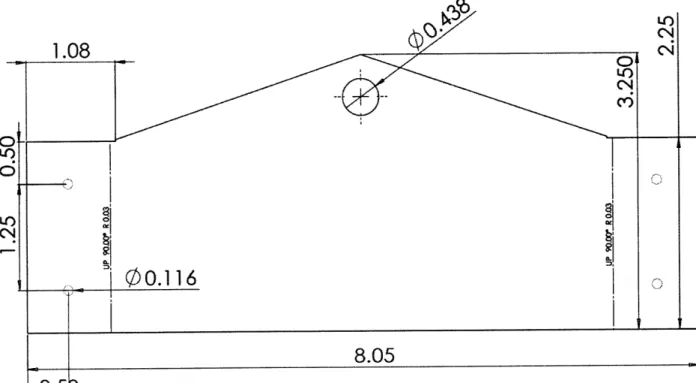
3.6 Brackets
The bottle is attached to the base using the same polycarbonate brackets that were used in the 2009 version of the 2.670 robot. However, in the new design the brackets are attached to the main base and the actuator runs underneath them. The brackets must now be altered to sit on top of the actuator. The simplest way to do this is to add extra material to the bottom and remove a section for the piston. .7 inches was added to the height of the bracket, which gives enough space for the piston to rest under it once a slot is removed. In this design, the bracket also serves to help constrain the piston. In the previous design the brackets were attached to the robot using a straight hole and a nut and bolt. In this design, because of the added length at the bottom, the bolt would need to be over an inch long. In place of that, threaded holes were added to the
bottom and each bracket was attached with two 6-32 screws. Each bracket is attached to the breadboard in the same manner as before, again with two 6-32 screws.
3.7 Back Axle
The back axle primarily serves to provide thrust for the robot. The robot is compact and does not require a wide wheel base for stability, so the wheels are positioned relatively close together. They are attached to the piston rod using a simple block with shoulder bolts that serve as axles that will interact with the one-way bearings. A self-locking bolt is needed for the left-wheel axle. The one-way bearing prevents motion in the same direction that the bolt would be unscrewed. The self-locking bolt is to prevent the axle from coming unscrewed during normal use of the robot. The end of the piston rod is threaded, so the back axle block is easily attached
to the piston rod by placing the block onto the rod and securing it with a nut.
1.00
1.00
0
0Ic
Figure 11: Part drawing for the back axle of the robot. 0
4. Assembled Design
The design of the individual components has been discussed, but these components now need to come together to make one robot. The actuator is attached to the back axle using a nut as described in section 3.7, but it still needs to be attached to the main base. The box extrusion that
serves as the pivot connection between the front wheel block and the rest of the robot has an inner width that is very close to the outer width of the end of the non-firing end of the actuator. The end of the actuator is placed into this extrusion and the hole that is already present in the actuator is lined up with the hole in the side of the pivot block. A 10-32 bolt is inserted that runs through the pivot block, the piston front clevis, and the base, and secured on the other side with a nut. A second bolt is then run through the side hole. This secures all three components to each other. The end of the actuator fits snugly into the pivot which prevents it from rotating about the bolt once it is secured. The base does not rotate as long as the bolt is kept tight and the brackets also serve to keep the base in line with the actuator.
Two nylon bushings are used for the connection of the pivot and the front wheel block. The bushings are placed into the holes drilled in the front wheel block, with the flanged end on the inside of the box. The pivot box extrusion is inserted between these two bushings and the aluminum rod axle equipped with the e-clip is run through the bushings and the pivot box.
The servo and steering mechanism is set up by first sliding the servo into the slot cut into the main base and then securing it using two 8-32 bolts. The servo arm is equipped with a small
2-56 screw with a ball on the end of it. Another one of these screws is screwed into the front
wheel block and they are connected with a ball link. In its initial state the servo arm is only free to rotate 180 degrees. It is important to ensure the servo arm is installed so that in its initial position it is able to rotate the front axis for the full turning radius.
The brackets are attached to the main base in the manner described earlier, with the use of two 6-32 screws. The bottle and air hose system is the same as in the previous design, with the only difference being that there is now one double-acting actuator instead of two single
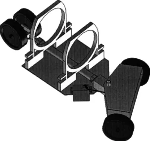
acting actuators, so the fitting from the second actuator now goes into the other end of the double acting actuator. A solid model of the final design without the 2-liter bottle and electronics is shown below.
Figure 12: Solid model of complete design
An unexpected benefit of this final design is that it is able to function in both directions. It was originally intended for the wheels attached to the piston rod to serve as the back wheels and push the robot forward while the front wheels provide the steering. However, since the back wheels are attached directly to the piston rod and are horizontally symmetric to the plane of the main base, the wheels can simply be flipped over and the robot turned around to create a robot that moves in the opposite direction. Now that the unidirectional wheels are flipped over the firing of the actuator from the starting position extends the back axle forward and the return fire of the piston pulls the robot forward.
5. Prototype
A prototype of the design was constructed for testing purposes. The prototype was made before the final design on each component was decided on, so some dimensions vary slightly from that of the final design that is described in this paper. A picture of the prototype is shown in figure 11. The prototype was subjected to several bench-level experiments designed to test basic functionality.
Figure 13: Picture of prototype.
The prototype performed well in the testing. The robot was sufficiently robust and no weaknesses were found in the structure. The propulsion system was tested using an air pump. The single actuator provided significant forward motion to the robot. With each firing of the actuator the robot moved forward the length of the stroke size and then also continued to coast, something the previous robot did not do. This means that the new design should be able to travel much further on one bottle of compressed air than the previous design. When the front axle was rotated the robot moved forward smoothly in an arc. However, the turning of the axle was done
when the robot was in a resting position, so it is not known how the robot would respond if the axis were turned while the robot was moving forward. On a basic design level the prototype seemed to perform very well and no major flaws were found in the design choices. However, the controls system was not implemented into the prototype and has not been tested.
6. Conclusions and Recommendations
The robot was designed with the goal of producing a compact, reliable and effective robot. A prototype was assembled from this design and put under tests to gain understanding of the basic functionality of the design. The prototype performed well and showed that the design is worth further exploring as a potential replacement for the current 2.670 robot. However, the tests were performed using an air pump instead of the bottle of compressed air that the actual robot would use and the tests did not make use of the BASIC Stamp Homework Board. In order to completely test the effectiveness of the design a Homework Board and a bottle with air hoses would need to be installed on to the prototype. Then it could be determined how well the robot responds to the microcontroller and how difficult the robot is to control.
The dimensions of the prototype are very similar to those of the final design, but before this design can be used in 2.670 a version of the robot built precisely as designed would need to be assembled to test for functionality. In addition to testing functionality, the assembly process must also be tested. The assembly of the robot must be done only with steps that are accurate and simple enough to be repeated by students with minimal experience. A preliminary discussion of the assembly process for students has been started and can be found in the appendix of this document.
In the future if this design or a similar design is chosen to be used in 2.670, it would be worthwhile to test a few options that could lower the price of the robot. The Homework Board and the actuator are the most expensive components. There is not much freedom with the
Homework Board, but there are many other choices that could be made for an actuator. Changes could be made in stroke length and bore size. In the current design a bore size of 16mm was chosen to provide structural stability. The prototype showed that this actuator is actually quite stiff and a smaller size will likely provide plenty of support for the lightweight robot. Lastly, if this design (or any new design) is chosen for 2.670, a detailed instruction booklet of how to machine and assemble the robot would have to be compiled.
Appendix: Assembly Instructions
This initial version of the assembly instructions was put together to begin taking a look at the process the students would need to go through in order to have a finished product. Some relevant dimensions are missing, but the point of this early attempt was to recognize any trouble areas in the assembly process and gauge the feasibility of the student assembly of this design.
The area where it seems like problems are most likely to occur is the assembly of the front wheel block. The two pieces are cut with flaps on both ends that are bent up and then joined together by either screws or rivets. If the holes are drilled before the flaps are bent it is
likely that the bends will not be made exactly on the intended line, which could result in the holes not lining up. An alternative to this would be to drill the holes through both pieces at the same time after the flaps have been bent, but this is also not easy.
Assembly Instructions
Main Base
For the preparation of the main base find the 6" by 8" piece of sheet aluminum. It should be the largest piece in your kit. Before this piece can be used, two cuts must be made and several holes must be drilled. A drawing for what the part should look like is shown below.
2.42
2.00
1.10
o0"o
4.00
1.125
o o6.25
,.
C<
o
Figure 1: Part drawing for the base of the robot.
The first step in preparing the base is to lay out the dimensions for drilling the necessary holes. The base requires a total of seven holes: four to hold the bottle braces, two to attach the servo, and one to attach the pivot block and actuator. An easy and accurate way to ensure that all of the dimensions are correct is to score lines at the appropriate heights and lengths across the base and drill where the lines intersect. A scoring instrument with a height indicator is available in lab that is very accurate. Before using the height gauge ensure that it is calibrated by lowering the head of the gauge to the table and making sure that the gauge measures zero. When scoring
the base secure the aluminum sheet against the piece of wood and slide it along the combination square that is provided. This will ensure that the sheet is perpendicular to the height gauge. A tilted sheet would result in inaccurate measurements. To keep from getting confused, mark the correct intersections with your marker before you drill the holes.
The holes should be drilled using the drill press with the appropriate drill bits. Be careful while drilling these holes, as the drill bit can grab the piece and spin it, which could hurt you if you are not paying attention. If this happens, remain calm and turn off the drill press. After drilling the holes be sure to file down any rough edges.
After the holes are drilled the next step is to remove the top two corners to reduce interference with the front axle that will occur when the robot is turning. The dimensions of these cuts are not as critical as the holes drilled earlier, but care should still be taken while measuring for the cut. Draw a line representing where the cut should be made and make the cuts using the notcher. For this case, the notcher can make the cuts faster and straighter than the bandsaw.
The only thing that remains to be done to the base plate is removing the slot for the servo. This cut will be made using the bandsaw. In cutting this slot you will be removing a rectangle from a larger rectangle. This is most easily done using the method shown in the figure below. Begin by cutting the sides (1 and 2) straight into the material. Next, a curved cut (3) starts near the beginning of the first cut and ends at the end of the second cut. Be careful to not push too hard on the blade while making this cut or the blade will break. After this piece has been removed, the blade is placed where the curved cut ended and the fourth cut is made to remove the rest of the material.
1
1
3
2Figure 2: Proper method for making a rectangular slot in a piece of sheet stock.
Wheel Block
There are two rectangular aluminum sheets in your kit that will be bent and joined
together to form the front section of the robot. The pieces must be cut to shape and fit with holes before they are bent and joined together. Dimensioned drawings of the top and bottom pieces are shown below. Cut the pieces to shape and drill the holes EXCEPT for the large center hole in the top piece. This hole will be drilled at a later time.
After the holes are drilled the flaps on either end can be bent up to a 90 degree angle. Pay special attention to the top piece, as the small hole for the ball link makes this piece asymmetric. With the front edge of the robot being the flat part the hole must be on the right. This piece is the top, so these flaps must be bent downwards while the hole is on the right side. If they are bent the wrong direction you will have to start over, so be sure that you have it in the correct orientation.
The flaps have now been bent, but before the pieces can be joined together the axle blocks must attached to the bottom piece. These pieces hold the wheels, so it is important that the outer edges of the blocks are parallel with the face of the flap. Place the wheel block in a
clamp and drill out only one hole in the position shown below. Now that this hole is drilled attach it to the bottom piece of the front wheel blocking using a pop-rivet. Ensure that the edges are parallel and that the threaded hole is facing outwards. Re-clamp the block and drill the second hole, passing the drill bit through the pre-drilled hole in the sheet. After the hole is drilled, insert another pop-rivet. Repeat this step for both wheel blocks.
After these blocks have been attached you can now connect the two pieces. The bottom piece should fit inside the top piece and the four holes should align. The four small screws and bolts in your kit are used to secure these two pieces together.
The two pieces should now be joined together and you should have one block. Now is the time to drill the large center hole in the top piece. This hole is used to hold the pivot axle, so it is very important that the two holes are lined up or the axle will not fit. To ensure that the holes are lined up, flip the piece over and drill the hole in the top piece by first running the drill bit through the hole in the bottom piece that has already been drilled. Do this slowly so that the bottom piece does not deflect and the two holes will be aligned.
Pivot Block
The Pivot Block is made using the 1/8" aluminum box extrusion. It is the thicker of the two extrusions that are in your kit. The piece should be cut into a 2" piece. This cut can be made using the bandsaw. Before cutting ensure that the guide is positioned two inches from the blade. Keep the end of the piece pressed against the guide to ensure a straight cut. After the cut is made, the piece should be filed to remove rough edges. There are three holes that need to be drilled after the piece is cut. Again, while drilling these holes the piece must be clamped.
0.50
0.50
I Ii
Figure 3: Part drawing for piston block.
Back Axle
The back axle which connects the back two wheels to the piston rod is made from an aluminum rectangular box extrusion (2" by 1" with 1/8" wall thickness). The piece in your kit should already be cut to a length of 1/2" so the only remaining step is to drill and tap the holes. Three holes need to be drilled in the stock piece that you are given: Two for the shoulder bolts that will serve as the axles for the back wheel and one to connect to the piston rod. Place the stock piece in a clamp with the long side facing up. Drill a hole in the middle of the face that runs through both sides of the piece. Next, turn the piece so that the short face is facing up and drill a hole in this face.
1.00
1.00
Figure 4: Part drawing for back axle.
These holes must now all be tapped with a 10-32 size tap. Before you begin, place a drop or two of cutting fluid in the hole. You can then place the end of the tap in hole and begin
tapping. Turn the tap clockwise a few times just as if it were a screw you were screwing into the hole. After a full turn or two, reverse the turning of the tap to remove any shavings that you have made. This will make for a cleaner tap. Throughout the process be sure that the tap remains vertical. All three holes require the same tap, so repeat the process for all three holes. Assembly
The first step in the assembly is to attach the pivot block to the front wheel block. There are two nylon bushings included in your kit. They should be inserted into the two holes of the wheel block, with the long end of the bushing sticking out of the block. The pivot block should be inserted between these two bushings and the larger hole in the pivot block aligned with the hole in the bushing. The aluminum rod can then be pushed through the bushings and the pivot block, connecting them. The fit is snug, so the holes must be aligned exactly for this to work.
Next, you can attach the pivot block to the actuator and the main base. The hole in the pivot block should be aligned with the hole on the main base and the two then connected using the 1.5" screw that is in your kit. After this is secured, you are ready to connect the actuator. There is a hole at the non-firing end of the actuator that goes all the way through the double-clevis end attachment. This end of the actuator should be inserted into the end of the pivot block with the clevis straddling the screw. The hole in the clevis should then be aligned with the hole in the side of the pivot block and attached using another 1.5" screw. Make sure that when you do this that the air port is facing away from the servo so that the hose can easily be connected to it. The three components are now all secured together.
Now that the front and back sections of the robots are connected you can connect the steering mechanism. The servo should slide into the slot that you cut earlier and can be secured with two small screws. Screw another ball screw like the one in the front wheel block onto the servo arm. The servo arm and the front wheel block can now be connected with a ball link. The servo arm is only capable of turning 180 degrees so ensure that while the robot is facing
forwards the servo arm is in the middle of its turning radius. If it is not, you can remove the screw that connects the arm to the servo and move it so that the robot will have its maximum turning ability.
The polycarbonate brackets can be screwed onto the base by aligning them with holes that were already drilled into the main base. Fasten the Homework Board to the front and rear brackets with four 6-32 screws. One of the screws used to do this should be longer than the others to hold the pump fitting. The pneumatic system including the bottle, the air hoses, and all of the connections can now be added to the robot. The bottle slides into the brackets. It might feel a little loose at first, but should tighten up when the bottle is pumped up.
The final step in assembling your robot is to attach the back axle to the actuator rod. The end of the rod is threaded, so simply screw the rod into the piece and secure it with a nut on the other side.
References
[1] https://wikis.mit.edu/confluence/download/attachments/33751587/Robot+Directions.pdf [2] http://www.servocity.com/html/hs-322hd standard deluxe.html
[3] http://store.cylindersonly.com/nci2d 16-600.html [4] http://www.smcetech.com

![Figure 2: 2009 version of 2.670 robot [1]](https://thumb-eu.123doks.com/thumbv2/123doknet/14722465.570742/8.918.231.748.557.938/figure-version-of-robot.webp)