Publisher’s version / Version de l'éditeur:
Proceedings of the 8th World Congress of Chemical Engineering 2009., 2009
READ THESE TERMS AND CONDITIONS CAREFULLY BEFORE USING THIS WEBSITE.
https://nrc-publications.canada.ca/eng/copyright
Vous avez des questions? Nous pouvons vous aider. Pour communiquer directement avec un auteur, consultez la
première page de la revue dans laquelle son article a été publié afin de trouver ses coordonnées. Si vous n’arrivez pas à les repérer, communiquez avec nous à [email protected].
Questions? Contact the NRC Publications Archive team at
[email protected]. If you wish to email the authors directly, please see the first page of the publication for their contact information.
NRC Publications Archive
Archives des publications du CNRC
This publication could be one of several versions: author’s original, accepted manuscript or the publisher’s version. / La version de cette publication peut être l’une des suivantes : la version prépublication de l’auteur, la version acceptée du manuscrit ou la version de l’éditeur.
Access and use of this website and the material on it are subject to the Terms and Conditions set forth at
Towards the development of a virtual bitumen froth settling process
Kirpalani, Deepak M.
https://publications-cnrc.canada.ca/fra/droits
L’accès à ce site Web et l’utilisation de son contenu sont assujettis aux conditions présentées dans le site LISEZ CES CONDITIONS ATTENTIVEMENT AVANT D’UTILISER CE SITE WEB.
NRC Publications Record / Notice d'Archives des publications de CNRC:
https://nrc-publications.canada.ca/eng/view/object/?id=a24bf71a-b76c-44c5-9e0c-c5452726653b https://publications-cnrc.canada.ca/fra/voir/objet/?id=a24bf71a-b76c-44c5-9e0c-c5452726653bTOWARDS THE DEVELOPMENT OF A VIRTUAL BITUMEN FROTH SETTLING PROCESS Deepak M. Kirpalani
Institute for Chemical Process and Environmental Technology National Research Council of Canada
M-12 Montreal Road Ottawa, ON
K1A 0R6
E-mail: [email protected]
Abstract: Bitumen Froth, a highly viscous fluid, typically consists of 60% bitumen, 30% water and 10% solids by weight. The froth is generally treated with a hydrocarbon solvent to reduce the viscosity and density of the oil phase The type of solvent used has a significant effect on the settling behaviour of the dispersed phase The use of paraffinic solvents reduces the bottom sediments and water to less than 0.1% by weight due to partial precipitation of asphaltenes and large aggregate formation of water droplets, mineral solids and asphaltenes.
Zone settling induced due to solvent treatments increases the settling rate of B, S & W (contaminants), resulting in possible usage of gravity settling methods rather than energy intensive approaches such as centrifugation. However, conventional gravity settlers are fairly large and require large amounts of solvent. To reduce the footprint of such unit operations and increase energy efficiency, inclined plate settlers (IPS) systems are considered to be a suitable alternative.
This work describes the fundamental development of a computational model to predict hindered and compression settling bitumen froth with the goal of incorporating the model in an IPS system.
Keywords: Bitumen Froth Treatment, CFD, Inclined Plate Settler
1. INTRODUCTION TO BITUMEN FROTH SETTLING
Bitumen from shallow oil sands deposits, are recovered and processed primarily via surface mining, hot water extraction and froth treatment. Typically, bitumen froth consists of 60 wt% bitumen, 30 wt% water, and 10 wt% coarse sand and fine solids. The water and solids in froth need to be removed for further solvent-based processing (settling) of the bitumen. Bitumen aggregates, consisting of emulsified water droplets (WD), dispersed solids (DS), and precipitated asphaltenes (PA) are treated with aliphatic solvents. Efficient separation via froth treatment involves developing a detailed understanding of the local fluid – solid interactions and overall solid fluid theory of the settling or froth treatment systems. Advantages of further developing and controlling the settling process lead to lower downstream processing costs and lower hydrocarbon losses in the tailings, thereby enhancing resource utilization and has the potential to reduce GHG emissions from tailings ponds by over 1 million tons CO2E annually. Detailed knowledge of local fluid-solid interactions during settling and the solid-fluid dynamic interactions is critical for improving this process.
In recent years, computational fluid dynamics (CFD) has emerged as a powerful tool for understanding the multiphase interactions prevailing in such process systems. Its success in single phase processes is significant while the presence of multiple phases makes the description of the flow difficult to quantify. This requires the combination of fundamental process models that explain the local fluid-solid behaviour and the incorporation of the local models into CFD to determine the settling rates computationally. In this work, empirical results from Long et al. in a model froth settling system were applied to develop a CFD framework and the settling rates were determined using a new model by Kirpalani and Matsuoka as described in this work. In earlier work, Kirpalani and Matsuoka examined
the Richardson-Zaki exponent, outlined in the work by Long et al., further modeling in scaled froth treatment systems and alternate modeling approaches such as the Syamlal-O’Brien model, described by John and Maan was also examined for the low settling rates. Long et al. reported that bitumen froth treatment using aliphatic solvents can be enhanced (high settling fluxes can be achieved) by operating the settling system (mixing of bitumen froth with solvent and subsequent settling of the solvent-diluted froth) at elevated temperatures. Long et al. also determined the settling rates at different temperatures and described the irregular structure of bitumen aggregates. In this work, a framework for studying the numerical aspects associated with the bitumen settling process as a result of change in temperature have been examined for both hindered and compression settling. CFD results were validated by the settling tests conducted by Long et al.
Aggregate structure has been well-recognized to be of great importance to solid-liquid settling processes. The aggregate structure and density influence the strength of the aggregates and undergo growth, breakup and possible re-arrangement in settling systems. It has been widely accepted that flocculated aggregates can be represented by fractal structures. Fractal dimensions relate physical size to a geometric property in the equivalent dimension. In this work, volume based fractal dimension, D3 or D, has been used based on Euclidean geometry to describe the irregular structure of aggregates. Masliyah et al. measured the fractal dimension of asphaltene aggregates formed in toluene – heptane solvent mixture by settling experiments and imaging techniques. In this work, a new model for settling of aggregates was developed based on only the initial fractal dimension and other physical properties of aggregates and was implemented in the original Richardson – Zaki drag approximation to account for the aggregate structure. This approach minimizes the dependence on experiments for simulating settling rates and depends on initial WD/DS/PA properties only.
1.1 Phenomenonological Description and Development of a New CFD Model for Froth Settling Process
Bitumen aggregate concentrations of about 40% and higher tend to settle in “hindered settling” mode in which all solids, irrespective of their size, tend to settle at the same rate as the close proximity of the particles The solids or aggregates, thus settle to a smaller volume leaving a layer of supernatant above separated by a sharp interface. Kynch reported that this settling behaviour is only a function of concentration of solids and that the aggregates swarms move downward and a compacted zone moves upwards from the base of the settling column until it reaches the upper surface of the consolidating solids. As the solids settle and their concentration in the settled zone increases, the inflection point for hindered settling is eventually reached and the settling rate slows down as the aggregates rest on top of each other and compact under their own weight. At this point, the column consists of two layers (1) Aggregates settled over each other with the voids or interstitial spaces filled with liquid (oil) and (2) A supernatant or clear liquid (oil) above the aggregates. Each layer is separated by a sharp interface. Compaction or compression settling begins and the aggregates are expected to release liquid from the interstitial gaps between the aggregates that can be accounted for by the effective solids pressure and other solid properties and equilibrium is reached when the buoyancy forces of the liquid are balanced by the gravitational forces of the aggregates. The settling process is thus modelled as a two-step process; (1) Hindered settling and (2) Compression settling. The hindered settling process for the WD/DS/PA aggregates in solvent diluted bitumen can be modelled well by the Kynch theory of kinematic sedimentation as discussed by Long et al. The settling flux can be determined by the generalized settling rate model or the Richardson-Zaki approximation. The Richardson-Zaki approximation with the exponent terms proposed by Long et al. and the Syamlal-O’Brien model were implemented in Fluent Computational Fluid Dynamics (CFD) Software via the inter-phase exchange or drag terms.
Continuity and momentum conservation equations
The volume fraction balance equation is (q = L, S)
V q
q
dV
V
. (1)0
q q q q qv
t
. (2)The momentum conservation equation is
n p pq q q q q q q q q q q q
R
g
P
v
v
t
v
1 . (3) pqR
is the interaction force between the two phases. In this work, only drag force was considered. In general, drag force acting on a particle in fluid-solids system can be represented by the product ofmomentum transfer coefficient, KLS, and the slip velocity,
v
Lv
S , between the two phases: SL LS
drag
K
v
v
f
. (4)An earlier drag model was proposed by Richardson and Zaki: [3] 2
1
S n T S L S LSv
g
K
, (5)where S and L are the density of solids and liquid, respectively. S and g are the volume fraction of solids and gravity, respectively. The exponent n is depends on the Reynolds number based on terminal velocity, vT, of a single particle. For low Reynolds number (ReT < 0.2), n is 4.65.
Syamlal and O’Brien proposed a model of the two phase drag coefficient based on the terminal velocities of particles in fluidized and settling beds as shown in Eq. [4]
L S D S S R L L S LS
C
v
v
d
v
K
2 ,4
3
, (6)where dS is the diameter of particles. And the drag coefficient, CD, is expressed by 2 ,
Re
8
.
4
63
.
0
S R S Dv
C
, (7) L L S S L Sv
v
d
Re
, (8)where vR,S is the ratio of the settling rate of particles to the terminal velocity of a single particle. The expression of vR,S is 2 2 ,
0
.
5
A
0
.
06
Re
0
.
06
Re
0
.
12
Re
2
B
A
A
v
RS Sm Sm Sm , 28 . 1 LA
,85
.
0
65 . 2 L LB
,B
0
.
8
L1.28 L0
.
85
,2
.
0
Lm
. (9)These models, however, require a modified experimental exponent or other apriori knowledge of settling experiments for predicting the settling behaviour. Hence a model based on initial structure of aggregates was proposed in this work.
1.2 Fractal Model for Aggregate Settling Process
It has been widely accepted that flocculated aggregates can be represented by fractal structures (Masliyah et
al. and Li and Logan). Fractal structure of aggregates can be represented by introducing the fractal
– heptane solvent mixture by settling experiments and imaging techniques. In this work, the fractal dimension of aggregates was defined and implemented in the Richardson – Zaki drag model. From Stoke’s law, terminal velocity of a single particle is
L A T
d
g
v
18
2 , L P L E1
, (10)where subscript A and P represent aggregates and primary particles forming aggregates, respectively. is the initial porosity of aggregates and expressed by
3
1
A P A Pd
d
N
V
NV
, (11)where N is the number of primary particles forming aggregates. N is expressed with the fractal dimension,
D, as follow: D P A
d
d
N
. (12)Combing above equations,
L P A P D P A
d
d
d
d
3 , (13) D A P L A L P F Td
d
d
g
v
3 2 ,18
. (14)This expression of vT,F can be introduced in equation (5) for modelling the settling rate that accounts for the fractal structure of aggregates.
Compression Settling –Incorporation of kinetic theory of granular flow equations
Due to the high concentrations of aggregates in the settling system, a network or matrix of solids is
eventually formed in the suspension that shows a compressive yield value and in the compression zone. In the compression zone, the suspension can be considered as a network of channels through which the liquid flows upwards resulting in a slow subsidence rate of the interface between the concentrated suspension and the clear liquid. The subsidence rates of the layers of aggregates are controlled by the internal mechanism of consolidation or compaction in the matrix of solids. The characterization of porous beds (formed in compression range suspensions) is accomplished by accounting for the porosity and permeability of fluid through the porous matrix. These two parameters depend on the nature of the initial suspension and the subsequent loading, as determined by the effective pressure of solids. This solids pressure can be established as the pressure from which the structure of particles responds to changes in stress, and consequently is the pressure caused by the un-buoyed weight of solids above the layer considered.
Closure of the solids phase momentum equation requires a description of the solids phase stress. The granular kinetic theory derived by Lun et al. is adopted in this study. Analogous to the granular temperature S can be introduced as a measure of the particle velocity fluctuations,
2
'
3
1
S Sv
. (14)The solids phase stress depends on the magnitude of the particle velocity fluctuation. The granular temperature conservative equation is
,
:
2
3
LS S S S S S S S S S S S S Sk
v
I
p
v
t
(15)where
p
SI
S:
v
S is the generation of the energy by solids stress tensor,k
S S is thediffusion of energy, S is the collisional dissipation of energy, 2 3 2 , 0 2
1
12
S S S S SS SS Sd
g
e
, (16)and LS
3
K
LS S is the energy exchange between fluid and solids phase.The solids pressure is given by
S SS S SS S S S S S
e
g
p
2
1
2 0, , (17)where
g
0,SS is the radial distribution function expressed by 1 3 1 max , , 01
S S SSg
. (18)The solids bulk viscosity is given as 2 1 , 0
1
3
4
S SS SS S S S Sd
g
e
. (19)The solids shear viscosity developed by Gidaspow is as follows:
.
1
5
4
1
1
96
10
1
5
4
2 , 0 , 0 , 0 2 , SS S SS SS SS S S S S SS SS S S S kin Se
g
g
e
d
e
g
d
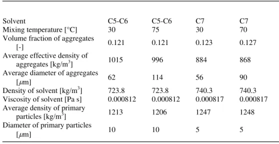
(20)Long et al. conducted settling experiments in laboratory columns using bitumen froth and two different aliphatic solvents, a 50/50 by wt light pentane/hexane solvent mixture (C5-C6) and a heavier n-heptane (C7) solvent at different temperatures, and obtained experimental settling curves. They also analyzed the aggregates structure and properties. The solvent and aggregates properties corresponding to the experimental conditions are shown in Table 1. The CFD model was developed and validated using experimental results on laboratory scale batch settling columns by Long et al..
The commercial CFD package FLUENT was used to simulate the settling of bitumen aggregates in liquid. The set of governing equations are solved by a finite control volume technique. To model settling columns used by Long et al. [2], two different 2-D symmetric numerical grids have been used. The columns diameter are 44 mm and the height are 370 mm and 1150 mm, respectively. The top of the column was set to 101.3 kPa and modeled as an open column. Liquid and solids phase properties were set according to the experiments described in their work and summarized as liquid and solids phase properties in Table 1. Interphase exchange term was implemented using user defined function (UDF) code in Fluent. The initial volume fraction of solids was patched to the numerical domain and the solution was initialized.
Table 1: Simulation Conditions taken from Long et al.’s bitumen froth settling experiments
Solvent C5-C6 C5-C6 C7 C7
Mixing temperature [°C] 30 75 30 70 Volume fraction of aggregates
[-] 0.121 0.121 0.123 0.127
Average effective density of
aggregates [kg/m3] 1015 996 884 868 Average diameter of aggregates
[ m] 62 114 56 90
Density of solvent [kg/m3] 723.8 723.8 740.3 740.3 Viscosity of solvent [Pa s] 0.000812 0.000812 0.000817 0.000817 Average density of primary
particles [kg/m3] 1213 1206 1247 1248 Diameter of primary particles
[ m] 10 10 5 5
Table 2
Solvent Mixing temperature [°C] Fractal dimension D [-]
C5-C6 30 2.7
C5-C6 75 2.7
C7 30 2.1
C7 70 2.4
Modification of Solids Pressure Using Granular Flow Theory
The drag model which includes the effect of hindered settling and fractal dimension of particles has been introduced earlier by Kirpalani and Matsuoka. From the results, it can be concluded that the models have shown good agreement with experimental data from Long et al. for hindered settling zone. However, intermediate and compression zones were hardly represented by the models.
In the previous models, a multi-fluid granular model to describe the flow behaviour of a fluid-solid mixture was used. The solid-phase stresses are derived by making an analogy between the random particle motion arising from particle-particle collisions and the thermal motion of molecules in a gas, taking into account the inelasticity of the granular phase. As is the case for a gas, the intensity of the particle velocity fluctuations determines the stresses, viscosity, and pressure of the solid phase. The kinetic energy associated with the particle velocity fluctuations is represented by a pseudo-thermal or granular temperature which is proportional to the mean square of the random motion of particles. For
intermediate and compression zones, however, the particle motion is not like that of gas and the stresses, viscosity, and pressure of the solid phase should be represented by other effects, such as successive collisions between particles.
To model the intermediate and compression zones, solids pressure and frictional viscosity were modified in this work.
The expressions for solids pressure applied are:
cri S S S SS S SS S S S S S
e
g
p
2
1
2 0, , (21) cri S S M cri S S S SS S SS S S S S Se
g
A
p
0, , , 21
2
………….(22)where S,cri is the critical volume fraction of solids. A and M are the constants. The expression of frictional viscosity is:
D S fr S
I
p
2 ,2
sin
where and I2D are the angle of internal friction and the second invariant of the deviatoric stress tensor, respectively. The frictional viscosity is added to solids shear viscosity when the volume fraction of solids is beyond the critical volume fraction
3. Results and Discussion
Four cases of experimental data reported by Long that describe the use of C5 – C6 and C7 solvents for bitumen froth treatment at 30 °C and 70 °C were modelled and validated with experimental data as shown in Figs. 1 – 4. The fractal dimension for each test condition was obtained by calculating the settling velocity from eq. (14). The fractal dimensions obtained are based on the solvent used and are shown in Table 2 The fractal dimensions for the C7 solvent system are lower than those of C5-C6 solvent system, suggesting that the porosity of aggregates for C7 solvent system is higher than that of C5-C6 solvent system. The settling curves of these simulations show good agreement with experimental data in hindered settling zone and their inclusion in the model reduces the dependency of experimental variables.
For compression settling model development, the critical volume fractions of solids were set equivalent to initial volume fractions. The value of M was set to 1.695 for all cases, while the value of A are varied for each case. The value of A decreases with increasing average porosity of aggregates. Larger values of A result in higher solids pressure. Therefore, solids pressure decreases with increasing average porosity of aggregates. The values of A are considered to be directly related to particle and aggregate properties and further experimental work is required to confirm the findings and determine relationships for parameter A and the physical properties.
The limitation in the original Richardson-Zaki approximation, due to its development on spherical non-porous solids, for this work has been overcome by accounting for the non-porous and fractal nature of the aggregates. The general exponent n in drag model, suggested by Richardson and Zaki, has been used with the structure and properties of solids to develop a new settling model that simulates the settling behaviour of bitumen froth quite well. The fractal dimensions of C7 solvent system were also found to be lower than those of C5-C6 solvent system. This numerical approach outlines an alternate method for predicting settling rates and improving froth settling or intermediate oil sands processing.
REFERENCES
Gidaspow, D. Multiphase Flow and Fluidization: Continuum and Kinetic Theory Descriptions. Boston: Academic Press; 1994.
John, G., Maan, R.A. Velocity-voidage relationships for fluidization and sedimentation in solid-liquid systems. Ind Eng Chem Proc Des Dev 1977; 16:206-14.
Kirpalani, D.M., Matsuoka A. CFD approach for simulation of bitumen froth settling process – Part I: Hindered settling of aggregates. Fuel,87, 3, 2008, 380-387.
Kynch, G. J. A theory of sedimentation. Transactions of the faraday society 1952; 48:166-76.Long, Y., Dabros, T., Hamza, H. Stability of settling characteristics of solvent-diluted bitumen emulsions. Fuel 2002; 81:1945-52.
Long, Y., Dabros, T. Hamza, H. Structure of water/solids/asphaltenes aggregates and effect of mixing temperature on settling rate in solvent-diluted bitumen. Fuel 2004; 83:823-32.
Li, X.Y., Logan, B.E. Permeability of fractal agglomerates, Water Res 2001; 35:3373-80.Masliyah, J.H., Dabros, T., Rahmani, N.H.G. Fractal structure of asphaltenes aggregates. J Colloid Interface Sci 2005; 285:599-608.
Lun, C.K.K., Savage, S.B., Jeffrey, D.J. Kinetic theories for granular flow: inelastic particles in Couette flow and slightly inelastic particles in general flow field. J. Fulid Mechanics 1984;140:223-56
Richardson, J.F., Zaki, W.N. Sedimentation and fluidization: part I. Trans Inst Chem Engrs 1954; 32:35-53. ACKNOWLEDGEMENTS
The advice and support of the Dr. T. Dabros and Dr. W. Friesen of NRCan, Devon, Alberta, Canada is gratefully acknowledged. This work was funded by the PERD Oil Sands POL 1.1.1.
Participants in this work include Guest workers and Parallel Computational Support by Ron Jerome , NRC-ICPET.
0 10 20 30 40 50 60 70 80 90 100 110 120 0 5 10 15 20 25 30 35 40 45 50 55 60 Time, min U p p e r In te rf a c e L e v e l, c m Experimental Simulation, A = 150
Figs.(1,2): Validation of proposed hindered and compression settling models for C5 – C6 solvent diluted bitumen froth treatment at 30 deg. C (Fig. 1) and 70 deg. C (Fig. 2) – Experimental (data from Long et al. ) and simulation curve
Figs.(3-4): Validation of proposed hindered and compression settling models for C7 solvent diluted bitumen froth treatment at 30 deg. C (Fig.3) and 70 deg. C (Fig. 4) – Experimental (data from Long et al. ) and simulation curve
0 20 40 60 80 100 120 140 160 180 200 220 240 260 280 300 0 5 10 15 20 25 30 Time, min U p p e r In te rf a c e L e v e l, m m Experimental Simulation, A = 30 0 20 40 60 80 100 120 140 160 180 200 220 240 260 280 300 0 5 10 15 20 25 30 35 40 45 50 55 60 65 70 75 80 Time, min U p p e r In te rf a c e L e v e l, m m Experimental Simulation, A = 50 0 10 20 30 40 50 60 70 80 90 100 110 120 0 5 10 15 20 25 30 35 40 45 50 55 60 Time, min U p p e r In te rf a c e L e v e l, c m Experimental Simulation, A = 80