AUTOMATED LOT DISPATCHING IN SEMICONDUCTOR FABRICATION
byYoel Roznitsky
B.S., Mechanical Engineering Cornell University, 1996
Submitted to the Sloan School of Management and the Department of Mechanical Engineering in partial fulfillment of the requirements for the degrees of
Master of Science in Mechanical Engineering and
Master of Science in Management
In Conjunction with the Leaders for Manufacturing Program at the Massachusetts Institute of Technology
June 2001
© Massachusetts Institute of Technology, 2001. All rights reserved
Signature of Author
Certified by
Sloan Sc f Management epartment
of
ancal EngineeringMay 5, 2001
~~~
~Sara
L. Beckman Senior Lecturer, Haas School of Business, University of California, Berkeley~~~~esis Advisor
Certified by
5onald B. Rosenfield
Seniqr Lecturer, Sloan School of Management 'Ihesis Advisor Certified by
Stanley B.Gehwin Senior Research Scientist, Department of Mechanical Engineering Thesis Advisor Accepted by
Margaret C. Andrews Executive Director of Master's Program 4 s School of Management Accepted b,
Ain Sonin Chairman, Departmental Committee on Graduate Studies Department of Mechanical Engineering
MASSACHUSETTS INSTITUTE
OF TECHNOLOGY
JUL 1 6 2001
AUTOMATED LOT DISPATCHING IN SEMICONDUCTOR FABRICATION
by
Yoel Roznitsky
Submitted to the Sloan School of Management and the Department of Mechanical Engineering on May 11, 2001 in partial fulfillment of the requirements for the degrees of
Master of Science in Mechanical Engineering and
Master of Science in Management
Abstract
Intel utilizes a commercial system for the real-time dispatching of lots. Encoded dispatching rules govern the flow of material through the factory, thereby affecting output and throughput commitments. This thesis seeks to develop and implement dispatching rules to enhance factory performance and reduce operational burden on the factory floor. Constraint management practices are employed to motivate the use and assess the implications of the proposed dispatching algorithms.
Thesis Advisors:
Stanley B. Gershwin, Senior Research Scientist, Department of Mechanical Engineering Sara L. Beckman, Senior Lecturer, Haas School of Business, University of California, Berkeley Donald B. Rosenfield, Senior Lecturer, Sloan School of Management
ACKNOWLEDGMENTS
I want to gratefully acknowledge the support and resources made available to me through the MIT Leaders for Manufacturing (LFM) program, a partnership between the Massachusetts Institute of Technology and major manufacturing companies.
I would like to express my gratitude to several individuals at Intel Corporation who have been instrumental at supporting my efforts. Sean Cunningham turned out to be more than a supervisor, but rather an exceptional mentor who provided support, patience, and advice, throughout my internship as well as afterwards. Joanna Shear proved to be the perfect coach whose direction ultimately led to many of my successes. Again and again she would prove that there is a solution to every problem, regardless of its perceived complexity. Steve Bullington, possibly one of the most dedicated individuals I have ever met, always made the time in his busy schedule to lend a hand and offer his keen insight into Intel's manufacturing
environment. Additional thanks go out to other members of the Manufacturing Systems Engineering group at D2, namely, Chris Keith, David Work, Dave Auchard, and Hyung Kang. Without the support network of all these individuals the work presented in this thesis would not have been possible.
I would also like to thank my advisors, Sara Beckman and Stan Gershwin, for their guidance during my internship and during the writing of this thesis. Finally, I would like to show my appreciation to Don Rosenfield for offering a hand in getting this work through its final hurdle.
TABLE OF CONTENTS
A cknow ledgm ents ... 3
Table of Contents... 3
List of Tables ... 6
List of Figures ... 6
Chapter 1: Introdution and O verview ... 7
1.1 Problem Statem ent ... 7
1.2 M otivation... 8
1.3 D escription of Projects ... 9
1.4 Thesis Structure... 10
Chapter 2: Intels Manufacturing Environment...10
2.1 Introduction... 11
2.2 M anufacturing com plexities... 12
2.2.1 Reentrant Product Flow s ... 12
2.2.2 E quipm ent Reliability ... 14
2.2.3 E quipm ent Characteristics and Restrictions ... 15
2.2.4 Shared Facilities... 17
2.2.5 Random Yields ... 17
2.3 Consequences... 18
C hapter 3: A utom ated Lot D ispatching ... 21
3.1 W hat is autom ated lot dispatching. ... 21
3.2 Technical Infrastructure... 21
3.3 O rganizational Infrastructure ... 23
3.4 D ispatching Rules ... 25
3.5 D ispatch Com pliance ... 29
Chapter 4: Evaluation of Current Dispatching Policies ... 31
4.1 G eneral Sort Rule... 31
4.2 FastBox 3-2-1... 33
4.3 M icro-policies ... 36
4.4 D ispatching at W et Stations... 38
4.6 Fram ew ork for rule developm ent... 41
Chapter 5: Evaluation and recommendation ... 44
5.1 Back End E valuation... 44
5.2 Ratio Rule...49
5.3 Im plem entation in Production ... 52
C hapter 6: A nalysis... 54
6.1 State of the Factory... 54
6.2 Shift-based A nalysis ... 56 6.3 O peration-based A nalysis ... 57 6.4 Cycle T im e A nalysis... 59 6.5 Photolithography Cascades... 60 6.6 Factory O utput... 61 C hapter 7: C onclusion ... 63 B ibiliography...65
LIST OF TABLES
T able 1: G eneral Sort R ule ... 32
Table 2: Back End Loop Cycle Tim es ... 46
Table 3: Ratio Rule Sum m ary ... 50
Table 4: CVD Output Performance by Shift Before and After Ratio Rule Implementation .... 57
Table 5: Average Output by Operation Before and After Ratio Rule Implementation ... 58
Table 6: Average Cycle Time by Operation Before and After Ratio Rule Implementation...59
Table 7: Output and Cascade Size at VIA across 8 steppers ... 61
Table 8: Fab Output Performance Before and After Ratio Rule Implementation...62
LIST OF FIGURES Figure 1: Actual microprocessor product flow... 13
Figure 2: Three Dimensions for Improved Utilization...19
Figure 3: Factory Scheduler Architecture... 22
Figure 4: New Factory Scheduler Team Organizational Chart...25
Figure 5: FastB ox ... 35
Figure 6: Im plant W eb Page ... 41
Figure 7: Framework for Rule Development... 42
Figure 8: Back End Flow D epiction ... 45
Figure 9: Skew ed W IP Profile... 47
Figure 10: ILD and VIA Average W IP levels...55
Figure 11: Wafer Output by Shift (Pre and Post Ratio Rule)... 56
CHAPTER 1: INTRODUTION AND OVERVIEW
1.1 Problem Statement
Intel Corporation's most profitable business involves the design, manufacturing, marketing, and distribution of silicon based products, mainly microprocessors, flash memory, and chipsets. Intel has long considered its manufacturing proficiency a core competency. Its excellence of manufacturing execution has kept Intel's share of the microprocessor market close to 80 percent, making it a leader in the highly competitive semiconductor market.
Semiconductors are manufactured in highly capital intensive and logistically complex fabrication facilities, often referred to as "fabs". Within a fab, an entering bare silicon substrate (wafer) is transformed into a microprocessor through a reentrant processing route consisting of more than 450 operations. Silicon wafers are transported from one workstation to another in lots of 25, yet at the workstation they may be processed one at a time. The re-entrant flow environment is further complicated by the introduction of multiple processes (such as, several generations of logic and flash processes) and multiple routes (for multiple product variants). All in all, the manufacturing environment is very complex. At any particular workstation in the fab, multiple products, traveling through various routes (calling for different sequences of operations) arrive at various states of completion.
Intel's fabrication facility in Santa Clara, CA is named D2 for Development Fab 2. It is responsible for Intel's flash memory development as well as several continuous improvement programs across its logic line. As a result, D2 is in a unique position relative to Intel's other fabrication facilities. It tends to run six to seven processes at differing stages of their life cycles, as opposed to one to two processes at the other, higher volume fabs. As the number of processes increases, and production volumes vary from process to process, the complexity of the manufacturing environment expands.
Due to the complexity of the flow environment, lot dispatch, the choice of what lot or lots to process next on a workstation, is a primary contributing factor to factory performance.
Dispatch rules govern the flow of material through the facility. Depending on the formulation of dispatch lists, material at the top of the list will move faster than material at the bottom. Some material may not move for a very long time, because it may continually remain lower on the list as more material arrives at the workstation. All in all, dispatch rules govern
demonstrated cycle time through the line, and thus greatly affect factory throughput and committed output.
Intel Corporation uses commercial software for real-time dispatching of lots. The lot dispatcher uses real-time data from the factory Manufacturing Execution System (MES), combined with standard work rules by workstation, to develop a rank-order list of lots to be processed on the workstation. At times, these work rules, or dispatching policies, can promote first class performance. At other times, they may hinder execution and lead to inventory buildups, excessive queue times, and overall poor factory output performance. It becomes critical for a manufacturing organization to adapt dispatching policies to account for the complexities of its manufacturing environment. This thesis introduces several lot dispatching projects that have been implemented in production at D2 to improve factory performance and floor operations. A brief description of projects in presented below in section 1.3.
1.2 Motivation
Lot dispatch rules are used to derive rank-order lists of lots that support the fab's WIP (work-in-process) management philosophy and achieve committed factory throughput and product output commitments. These complex dispatching rules are executed automatically, "behind the scenes". Floor personnel are no longer burdened with the complexities and the stress of complicated dispatching rules. Instead, they are instructed to simply follow the rank-ordered list of material presented at each workstation, and to select the lot at the top of the list as the next lot to be processed. Floor personnel do not have to be regularly re-trained when modifications and improvements are made, thereby allowing great flexibility for continuous improvement efforts.
Dispatching rules can simplify workstation demands by incorporating certain workstation practices into an automated algorithm. For example, if batching can be performed
automatically, workstation operators are no longer required to match lots with each other in an attempt to create batches. The factory is a physically and mentally demanding environment, and personnel are rarely idle. Floor personnel, as well as management, agree that removing the burden of certain repetitious tasks to an automated system is helpful in improving utilization, output and factory throughput.
The motivation behind this thesis and the work performed at Intel was the prospect of a flexible dispatching system that enables ongoing continuous improvement activities through the automation of WIP management policies and factory floor practices.
1.3 Description of Projects
Several dispatching projects were undertaken at Intel. All began with a performance evaluation of particular equipment sets. Selection of these equipment sets was based on factory indicators that tracked metrics such as cycle times, output performance to goal, inventory turns, WIP levels, and more. In certain situations, poor performance was due to equipment availability issues, while at other times it was due to a combination of reasons, one of which was improper dispatching of lots. Dispatching policies at batch tools, such as the wet stations and implant, did not account for actual operational requirements calling for the
batching of lots at these tools. As a result, operators were required to expend additional energy to manually match material and create batches. Due to the complexity and the demanding environment, doing so manually often opposed the WIP management policies encoded within the lot dispatching system. New dispatching policies were developed to enable automated batching at the wet stations and implant tools to alleviate batching demands at those workstations while guaranteeing adherence to the factory's WIP management practices.
A more elaborate project was undertaken at a Chemical Vapor Deposition (CVD) equipment set. Due to its unique placement at the back end of the production line, this CVD equipment set was observed to improperly dispatch lots thus affecting feeds to the back end constraints
and jeopardizing overall factory output commitments. A new rule was developed to first correctly prioritize material at the CVD station and move it to areas of low WIP inventory, and second to feed those downstream constraints expecting the least amount of work. Analysis of the rule's effect demonstrated improved utilization at the downstream constraints, as well as a 13% decrease in overall factory output variability. Output variability at the CVD workstation actually increased slightly, possibly due to additional work-in-process that moved into the area.
The dispatching policies implemented in production were developed in close coordination with factory floor personnel. When rolled into production, these policies were successful at alleviating execution pressures in those functional areas. The work performed at the CVD workstation went even further. There, policies implemented locally resulted in improved performance elsewhere, indicating the possibility of a locally induced remedy that can affect downstream entities, as well as overall factory performance.
1.4 Thesis Structure
This thesis will describe the work performed by the author, a member of a team, at Intel's D2 facility in Santa Clara, CA. Chapter 2 presents an introduction to the complexities inherent to semiconductor wafer fabrication. It is aimed at justifying the need for an automated lot dispatching system. Chapter 3 introduces the technical and organizational infrastructure behind Intel's lot dispatching system. It also draws a link between Intel's lot dispatching policies and research-based literature that had long sought out improved dispatching
methodologies. Chapter 4 introduces Intel's WIP management policies as encoded into its lot dispatching system, and proposes a framework for future policy development. It also
introduces two policies developed to ease operational burden on the factory floor. Chapter 5 utilizes the fundamentals introduced in previous chapters to evaluate a dispatching policy at
the CVD equipment set. The chapter introduces the implementation of the Ratio Rule, developed to combat apparent problems at this particular workstation. It also provides in-depth post-implementation analysis of the Ratio Rule's effect on local and overall factory performance. Chapter 6 completes this thesis with a conclusion of findings.
CHAPTER 2: INTEL'S MANUFACTURING ENVIRONMENT
2.1 Introduction
Intel's core business, accounting for over 80 percent of its revenue and an even greater component of its profits, is the design, manufacturing, and distribution of microprocessors, memory products, chipsets, and other integrated circuits (ICs). As a leader in the
microprocessor industry, Intel has historically been very successful at designing and delivering advanced products to market in a timely manner and at sufficient volumes. Bottom-line, as seen through the eyes of the author, is that within a very competitive industry it is
manufacturing competency that has dictated Intel's ultimate success within this marketplace.
As a consequence, it makes sense to evaluate Intel's manufacturing environment. Semiconductor wafer fabrication calls for possibly the most complicated manufacturing processes currently used by industry in high volume applications. The fabrication process begins with a bare silicon substrate and ends with a complete wafer consisting of a number (anywhere from several to hundreds) of functioning microchips. Within the four walls of a wafer fabrication facility (often referred to as afab), the silicon substrate is taken through a
carefully designed sequence of thin film depositions, etchings, photolithography, and ion implantation processes that form a transistor layer and multiple subsequent interconnection layers. The transistor layer is essentially the brain of the microchip and is often comprised of millions of transistors sized at critical dimensions of 0.18 microns (180 billionths of a meter) or smaller. Interconnect layers of metal and insulators follow transistor formation in order to connect the millions of transistors to one another and to dictate the functionality of the product.
These highly complex processes are performed in highly capital-intensive facilities housing extremely technical and expensive equipment. Interestingly, while the equipment is technically complex and highly automated, the labor content necessary to fabricate wafers is still very high.
Hundreds of operators are needed to load and unload these systems and to maintain smooth operation of such a facility. Ironically, it is the lowest paid employees within the organization that add the most value to the product. It is the operator on the factory floor that has the ultimate control over the realization of revenue for the company. The ultimate success of delivering a product to market relies on the proficiency of the manufacturing organization to develop a manageable system to utilize this capital effectively.
2.2 Manufacturing complexities
The fabrication complexity of such a system is described below through five characteristics inherent to Intel's manufacturing environment.
2.2.1 Reentrant Product Flows
The number of operations along a single product flow is very large and nowadays can often number as much as 500. Microprocessors and hybrid Integrated Circuits (ICs) become more complex as designers try to cram more transistors and added functions on a single silicon package. The number of operations necessary to bring these designs to market increases dramatically. It is typical for a single workstation to perform multiple operations. For example, a product that calls for 5 layers of metal interconnects, the circuits that connect transistors on a chip, may visit the same lithography tool 5 times at different points along its route in order to have the appropriate circuits imprinted. A flow where a lot visits a
workstation more than once is known as reentrant flow. Semiconductor wafer fabrication is an extremely reentrant process. Figure 1 depicts an actual workstation-to-workstation flow for a microprocessor product, where each number represents a unique workstation, or equipment set.
547 55 53 7 20 9 52 12 5 4 ~- 1 13 47 Figure\1: At 29 43 48 44 4 20 25 27 2924 224 26 4 21 40 2 2 30 56 39 35 3 37
Figure 1: Actual microprocessor product flow
An arrival at a workstation denotes a unique operation along the product flow. Certain workstations see material arriving at several instances along the product flow. These stations can also feed different downstream stations based on the lot's relative location along its process route. Others may only be used for a single operation during the processing of this particular product. Each workstation on this diagram might be used for the fabrication of one or more other products in this particular fabrication facility. So, while the diagram above may seem complex, actual complexity is increased dramatically by overlaying the multiple products flowing through the fab.
Multiple products are used to target various segments of the market. Within microprocessors, products may segment the market based on speed, architecture, power consumption, and various other attributes. In order to provide the customer a breadth of options, small
variations in the main process flow increase the complexity of a particular product flow. In fact, the figure above represents a specific product line item.
In addition to multiple products, today's fabs may no longer be dedicated to a particular
process. Intel's D2 is a prime example of a fabrication facility within which multiple processes, ranging across the wide spectrum of technology from microprocessors to flash and digital to analog, share capacity resources. At the time of this publication, D2 was running 7 different processes at varying volumes. Indicating such complexity in a single diagram is not possible.
2.2.2 Equipment Reliability
Wafer fabrication facilities are highly capital intensive. A typical 200mm wafer fab these days may cost up to $2 billion, while 300mm wafer fabs will probably require an overall investment close to $3B. While cleanroom space is highly expensive, the bulk of the funds required to outfit a wafer fab is used for the purchase and installation of highly technical and expensive fabrication equipment.
While semiconductor manufacturers pay premium prices for highly technical equipment capable of producing critical dimensions on the order of 0.1gm, they do not necessarily acquire the reliability necessary to do so repeatedly. Technological advances in
photolithography, chemical and physical vapor depositions, dry etch, and implantation constantly push the envelope of technical feasibility. The types of solutions provided by semiconductor equipment manufacturers have been remarkable, pushing the limits of science to an extreme. As a result, process windows have been continuously shrinking thereby affecting the reliability of these expensive systems. The end result has led to highly sophisticated tools running marginally stable processes. Moreover, the type of hardware necessary to achieve these processes has been novel and typically one of a kind. One of the main causes of uncertainty in this type of manufacturing environment is still unpredictable equipment downtime [Uzsoy, 1992].
2.2.3 Equipment Characteristics and Restrictions
With equipment reliability an issue, several restrictions on the use of equipment have emerged to combat characteristics inherent to the nature of these highly sophisticated systems. Four restrictions are highlighted below.
Soft Dedication
A wafer fabrication facility operates as a job shop. Individual systems are arranged in
equipment sets and are most often located in a common bay. This arrangement simplifies and reduces the costs of equipment installation. Moreover, due to the complexity of system
operation and maintenance, manufacturing technicians are most often trained on and dedicated to a single equipment set. By positioning like systems together, operation-based economies of scale are met. While all systems within an equipment set are physically identical, their process capabilities may not be. In most cases, the reasons for process anomalies
between systems are unknown and manufacturers learn to run their factories with such
limitations. To combat these limitations, a manufacturer may opt to process a lot on a specific system within an equipment set due to its superior process results. In such case, this particular system is dedicated for a particular operation due to its superior performance. Only those lots that arrive at the operation could be processed on the system. Such dedication is noted as soft because it is decision-based and does not conform to a physical limitation. For example, if one particular tool goes down for maintenance, the manufacturer may transition the operation to another system that is up for production with inferior process results. The manufacturer may prefer to keep the lot moving and might be willing to take the yield hit associated with the inferior process results.
Hard Dedication
While soft dedication does not reflect a physical limitation, hard dedication does. This limitation is due to a system's inability to perform to specification because of an underlying hardware restriction. An example of hard dedication can be seen in the photolithography equipment set. Lithography systems are used to imprint circuitry images on the wafer surface. These imprints are then used to define transistors, interconnect lines, source/drain locations, etc. In reality, they define the chip's functionality and performance. In achieving the types of
critical dimensions prevalent today, Intel and other microprocessor manufacturers expend much energy and money on technology development efforts in lithography. It is these
lithography systems that tend to propel Moore's Law by enabling doubling of clock speeds and number of transistors on a single chip every 18 months. In order to achieve the tolerances necessary to maintain these tremendous strides, imprints must align perfectly with underlying chip circuitry. Often, this requires a lot, imprinted on a particular lithography system, to return to the same exact system for subsequent processing. This type of dedication is
hard
because the physical limitations of the system prevent the manufacturer from sending this lot to a different system. By deviating from this policy, the manufacturer may not yield operational chips at all.Operational Dedication: changeover dependence
Operational dedication is a combination of both soft restrictions set by the manufacturer and hard restrictions inherent to the system. Consider a system capable of performing several operations, yet each operation affects the performance of the system in a certain way. By running a certain operation, the etch rate of the system might degrade. By running a different operation, etch rate may actually increase. With certain operations degrading the performance of the equipment, and certain operations improving performance, operational dedication becomes a means by which a manufacturer may sequence material to maintain the time a piece of equipment is available for production. Great care is taken to keep track of the operations performed on a given system and to prioritize work-in-process based on operational effects on that system. Operational dedication thus becomes a restriction, as well as a tool for managing fab performance.
Time Expiry
Throughout the wafer fabrication process there are critical time windows that must be
preserved between operations along the process route. A pre-clean performed in order to strip a wafer of native oxide (oxidation of silicon exposed to air) that has grown during transit must be followed by the subsequent deposition operation within a controlled period of time. In this case, the pre-clean operation will exhibit a time expiry restriction promoting the urgency of the lots traveling through the pre-clean station. If a lot is not processed through the deposition operation in time, the loop must be repeated in order to ensure predicted yields. Time expiry
loops pose additional complexities as they introduce time-related variables to an already complex environment.
2.2.4 Shared Facilities
As mentioned earlier, wafer fabrication facilities are highly capital intensive. Due to their cost, and the need for constant development of new products in the competitive semiconductor industry, fabrication facilities are often used for both production and development activities. There are some exceptions, such as High Volume Manufacturing (HVM) sites, that are constructed to ramp up production on a single process and are not used for new product development. These sites typically begin operations on a product that has already been developed and tested in smaller volumes. Intel's D2 facility is a development facility, but one that also runs production and contributes to Intel's bottom line. By meeting the demands of the market, D2 contributed to Intel's top line while continuing development of seven other technologies. The bottom line is that within the walls of a typical fabrication facility,
equipment sets must be utilized to process both production lots as well as development lots, all of which adds to further complexity. Conflicting goals between the manufacturing and engineering organizations add to the complexity as production and development material competes for priority in the factory. In an attempt to manage these conflicts, multi-level priority systems are enforced across work-in-process lots in order to speed up feedback of information on development lots, while maintaining high velocity for production lots.
2.2.5 Random Yields
Very often, historical data can be used to predict yields of mature products. Yet, with constant continuous improvement efforts and introductions of new products and technologies, yield estimation becomes a major problem [Uzsoy, 1992]. The effect of process changes on yield is not predictable. Interdependency among process factors leads to complex interactions that very often cannot be predicted. Moreover, variability inherent to production equipment and incoming material leads to enhanced uncertainty when process yields are concerned.
Environmental effects, such as temperature, humidity, and clean room class, may cause yields to vary in random fashion. All in all, while historical data may be useful in indicating expected
values, constant changes within the factory walls often lead to yields that may seem to vary randomly.
2.3 Consequences
The consequences of managing these complexities incorrectly may lead to the inability to introduce and develop new products, or even worse, serious operational shortcomings and loss of revenue. Specifically, by managing the complexities highlighted above incorrectly, one may adversely affect availability and utilization.
Availability refers to the proportion of time equipment is functioning, qualified, and available for production (as defined by SEMI International Standards in SEMI E10-0301). Equipment reliability, characteristics, and restrictions, as well as the dual production-development nature of a fabrication facility can severely limit the time equipment is available to process material. Manufacturers that have developed the proper systems, such as statistical process control, to track equipment performance, have found success in staggering preventive maintenance and complementary tasks in a way to maximize effective availability of their equipment base.
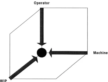
Utilization is the percentage of time equipment is processing wafers. Utilization of a particular system is bound from above by its availability and from below by three factors. These three factors must be satisfied in order to successfully process and ship completed products. At each workstation, the proper equipment must be available for production, inventory must be there to process, and an operator must be on location to operate the equipment and load the wafers (Figure 2). Execution failure along any one of these three dimensions will prevent a lot of wafers from continuing along its pre-planned path. Regardless of which factor is not met, the end result is an opportunity loss observed through lower than expected utilization.
Operator
Machine
WIP
Figure 2: Three Dimensions for Improved Utilization
Fab management is constantly on the lookout for ways to improve the utilization of assets. By hitting all three dimensions highlighted above consistently, utilization is maximized. Missing any one signifies an opportunity loss. There has always been much focus surrounding the availability of equipment. In some respects, these efforts regarding equipment availability begin at the selection stage of such equipment. Manufacturers work closely with their suppliers to guarantee certain availability specifications and hold their suppliers to such purchase agreements. Availability enhancing continuous improvement programs are always
on the roadmap and gather much focus from both equipment suppliers and their customers. Likewise, the labor-staffing dilemma has been constantly researched throughout many organizations. Staffing voids are typically very visible to the factory floor as headcount is tracked on a shift by shift basis and staffing plans are updated on continuous basis. Goss
(2000) examined the staffing effects of a cross-trained workforce and its ability to affect capacity utilization.
It is WIP availability that very often remains unquantifiable in this complex manufacturing environment. WIP management policies are utilized to govern the flow of material within a fab to ensure that proper buffers are maintained throughout the fab. Yet, manufacturers must limit the amount of work-in-process circulating through the factory in order to decrease holding costs, decrease throughput time, and improve yields. As factory management
accounts for the tradeoff between too much WIP and not enough WIP, WIP management policies become increasingly more complex. Factory automation systems, including automated dispatch systems, allow for the automation of WIP management policies to improve utilization and factory performance. These systems rank-order WIP at workstations to manage the flow of material through the factory. By meeting the last of the three utilization factors, automated lot dispatch systems affect and improve overall factory performance. This thesis elaborates on the use of lot dispatching systems to improve actual factory performance at Intel's D2 facility.
CHAPTER 3: AUTOMATED LOT DISPATCHING
3.1 What is automated lot dispatching?
The previous chapter highlighted some of the complexities associated with semiconductor wafer fabrication. It went on to pinpoint the consequences associated with managing these complexities improperly. It was noted that due to the complexity of the flow environment, lot dispatch, the choice of what lot or lots to process next on a workstation is a primary
contributing factor to fab performance. Lot dispatch rules are used to derive a rank-order list of lots that supports the fab's WIP management philosophy and achieve committed factory throughput and product output commitments. Execution of complex dispatching rules is performed behind the scenes, within a factory automation system.
3.2 Technical Infrastructure
Intel uses an Integrated Scheduling System for Real Time Dispatching (ISS/RTD), or Factory Scheduler for short, of work-in-process (WIP) throughout its factories. This new scheduling system was introduced at the same time as Intel began development of its 0.18gm process technology. This particular process technology introduced new complexities that could not be handled by the scheduling product of record at the time. Many of these complexities have been highlighted in the previous chapter. Upon introduction, preliminary efforts concentrated on replicating the prevailing dispatching policies on this new, more powerful, dispatching system. Once Factory Scheduler (FS) proved to reproduce the scheduling capabilities of the legacy system, work began to extend dispatching policies to account for the additional
demands of the new process technology. In particular, policies at the photolithography tools were expanded to incorporate hard dedication restrictions required of the new process.
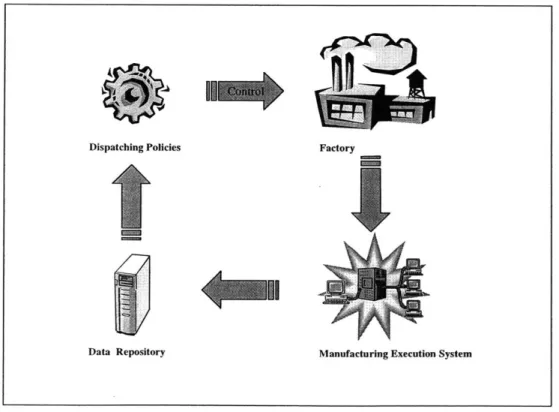
An overview of the Factory Scheduler architecture is provided in Figure 3 [Kempf, 2000]. A software tap into the factory's Manufacturing Execution System (MES) provides a repository
containing the current state of the factory. This data repository is temporal in nature, meaning that not only does it provide a current snapshot of the state of the factory, but it also archives historical data in order to provide past states for tracking and analysis purposes. Researchers of dispatching policies have long argued that adding spatial and time dimensions to the information provided by a manufacturing control system would improve decisions [Glassey and Petrakian, 1989]. In the past, generating this richer pool of data required substantial computing power that was not economically available. FS was introduced at a time that such limitations were being reduced dramatically, ironically, through Moore's Law and Intel's own contribution to this trend. The existence of a rich pool of data now enables users to compose WIP management policies via complex queries into the repository and deliver results to
operators based on automated dispatch rules. These dispatch rules govern the flow of material through the factory, thereby controlling factory-wide performance. The factory reacts to these policy engines while its health is continually recorded by the MES system, thereby closing the loop and providing a feedback control path to the policy engines. The user-programmed dispatch rules react to data from the MES system to drive material through the factory according to a prescribed WIP management policy.
Dispatching Policies Factory
Data Repository Manufacturing Execution System
3.3 Organizational Infrastructure
With the introduction of Factory Scheduler (FS), internal resources within the Manufacturing Engineering (ME) organization were allocated to export dispatching rules from the legacy system to FS. Furthermore, development of new dispatching rules and automated reports commenced in an attempt to harness the power of this new and improved scheduling system. Work along those lines began within the Tactical Capacity Group, a small group under Manufacturing Engineering. In time, to build on its continuous drive for improved factory performance, Intel's D2 management formed the Factory Scheduler Team to:
1. Explore opportunities for improvement through the development of new dispatch rules and reports; and,
2. Work with factory personnel to find potential areas for improvement, to increase awareness of the new system and its capabilities, and to push new dispatch rules and reports into production.
The Factory Scheduler Team was populated with members from three organizations, Manufacturing Engineering, Automation, and Operations, all of which offered a different resource necessary for the successful design and implementation of new factory rules and reports. While responsibilities were shared among participants, they often reflected the core competencies of the members' respective organizations. As such, these generalizations take form:
1. Members of the Tactical Capacity Group often spearheaded development of new dispatch rules and reports. Development began either through requests from the manufacturing and/or engineering organizations, or through internal discovery of improvement opportunities.
2. Members of Automation were responsible for the hardware and software agents behind the scheduling system. Responsibilities varied from sustaining activities to continuous
improvement efforts along the lines of FS. Often, members of the Automation group would also participate in the development and testing of FS-based reports.
3. Members of Technology Development (TD) Operations, possessing intimate knowledge of the manufacturing environment, reviewed requests and opportunities for their
operational validity. Moreover, as owners of TD performance, they offered insight into the interactions between production material and development/engineering lots. Their understanding of the production environment was essential during implementation.
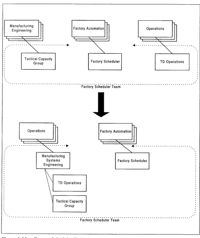
As highlighted by the two FS goals mentioned above, improvements in factory performance cannot be pursued via the academic development of rules alone, but rather through close coordination with factory floor personnel, individuals with complete knowledge of what affects factory performance. A pure engineering approach to the problem tends to ignore operational requirements and limitations, while a pure operational approach most often under-utilizes the power of the factory scheduling system. As a result, close coordination between Manufacturing Engineering and Operations is a prerequisite for successful projects. To aid in this close interaction, an organizational restructuring brought these two groups closer together (see Figure 4). The group was redesigned to bring the two disciplines together, not just for improved coordination on FS projects, but also in order to establish ownership of other manufacturing systems. The Manufacturing Systems Engineering (MSE) group was formed to own key factory indicators and to drive efforts and projects geared at improving on the current state of the factory. Factory Scheduler became one tool with which this group set out to follow its charter.
The strategic design of the Factory Scheduler Team brought organizational advantages that led to the success of the system. While the technical section above highlighted the need and power associated with this new dispatching system, it is the organizational structure and the customer-oriented focus of the MSE group that together harnessed its power and delivered directed solutions to the factory floor. Thus, it is important to think of the Factory Scheduler system as both an information technology product as well as an organization formed to enable its technical capabilities.
Manufacturing Engineering Tactical Capacity Group Factory Automation Factory Scheduler Operations ---. T \ p---TD Operations
Factory Scheduler Team
Operations Factory Automation
...---
-- -- - -- - - - -- - - . . . . ..
Manufacturing
Systems Factory Scheduler Engineering
TD Operations
Tactical Capacity
Group
Factory Scheduler Team
Figure 4: New Factory Scheduler Team Organizational Chart
The Factory Scheduler architecture along with its supporting organizational infrastructure has been introduced at Intel in order to develop dispatching rules to control the flow of material throughout its fabrication facilities. There exists no consensus, either at Intel or in the literature, as to what should be the objective of a scheduling system [Glassey and Resende,
1988]. One objective, that seems to echo through the literature, is minimization of cycle time, the amount of time a job spends at a workstation, or similarly, in the fab. By Little's Law
[Little, 1961], the minimization of cycle time is analogous to minimization of work-in-process, or equivalently, to minimization of total inventory cost. In the semiconductor industry, besides lower inventory, shorter cycle times improve manufacturing response time to market demand and unscheduled downtime. Moreover, shorter cycle times increase information turns, the frequency of information feedback, from inspection points, such as metrology equipment, that enable the diagnosing of defects and other process related specifications [Cunningham and Shanthikumar, 1996]. Much research has been performed on various dispatching algorithms, laying claim to perform better against these common objectives.
It can be argued that the need for studying and enhancing dispatching rules arises from the fact that given n jobs queued at a workstation, there are n!ways to sequence those jobs. Moreover, in a complex manufacturing environment, the state of work downstream, or elsewhere within the shop, might influence the optimal sequence of jobs at a workstation. In addition, even after decades of dispatching research, no one dispatching rule has been
demonstrated to be optimal for all job shop environments [Mittler, 1999]. Much of the work that has been published has been based on comparison-based simulations. These simulations have been used to test novel dispatching rules against 1) other known dispatching rules, and 2) against the simplest rule of them all, namely First-In-First-Out (FIFO). Under these studies, virtual factories are set up within a simulation package, and variability is often introduced in a controlled manner. All in all, whenever simulations are utilized, all variables leading to
manufacturing complexity, such as machine availability, are intrinsically known and predictable. The manufacturing complexities highlighted in Chapter 2 of this thesis can never be fully realized under the simulation approach. Therefore, conclusions reported in most literature almost always lack the empirical results necessary for implementation in a complex
environment such as wafer fabrication. Nevertheless, research has provided many of the building block elements and thinking processes used in today's WIP management policies.
A good example of a building-block policy, introduced in literature, supported through simulation, and adopted in practice is the prioritization of material based on Critical Ratio (CR). CR is a technique that considers a due date of a job relative to the current date and compares it to the expected lead-time remaining before it exits the factory. As a due-date-based dispatching policy, CR has been shown, through simulations, to demonstrate smaller variance of job lateness [Putnam, 1971]. In practice, at Intel, CR, when compared to the dispatching rules previously in production, has been shown to slightly reduce throughput time, and clearly decrease average lateness, as well as variance of lot lateness [Kempf, 2000]. The implementation of Critical Ratio within Intel's production facilities demonstrates the applicability of much of the research concentrated on improved dispatching policies. It is interesting to note that while CR has been around for several decades, its was only adopted at Intel in the last several years. In fact, the volume of data necessary to implement CR into an automated dispatching system was not available until the introduction of Factory Scheduler as a real-time scheduling system.
Blackstone (1982), compiled a comparative study of various algorithms based on the cost-effectiveness of each rule. The rules were evaluated in a simulated job shop environment where the only scarce resource is equipment, all jobs are independent, and each job is processed through a known set of machines. A large set of rules were subdivided into four classes: 1) rules involving processing times, 2) rules involving due dates, 3) rules involving neither times nor due dates (such as those that involve queue lengths), and 4) rules involving two or more of the first three cases. While it was shown that the shortest imminent (SI) operation rule, which selects the job for which the next operation can be completed in the least time, maximized throughput, it was Conway and Maxwell [1962] that pointed out that variances increased with the introduction of any shortest-operation rule. Such are some of the tradeoffs commonly seen in real operations. It is often the case that one dispatch policy cannot satisfy all metrics on the shop floor. As a result, at Intel, lot dispatch policies have been borrowing bits and pieces of carefully researched rules that have been studied via simulations but have not been placed into practice at a complex environment similar to Intel's. Any one of Intel's dispatching policies may exhibit characteristics borrowed from two or more of the classes mentioned above.
Where rules based on shortest processing times under-perform, rules based on due dates excel. The principal advantage of due-date-based rules over processing-time-based rules is a smaller variance of job lateness. This is where rules like Critical Ratio come into play. During the time of implementation at Intel, CR didn't replace an inferior rule, but was rather incorporated into a more encompassing policy consisting of other dispatching elements. Some of these elements targeted maximum throughput, while others optimized additional metrics, such as lateness. Another class of rules that is frequently seen around Intel is that based on queue levels at workstations on the shop floor. These rules, such LWNQ, select the job going next to the queue with the least amount of expected work per machine [Lu, 1994]. These rules have been used to drive WIP to areas which can handle it best, that is, areas with low WIP that can process incoming material quicker. Both of these rules compete with throughput maximizing rules, such as SI, by selecting the jobs that can be processed rapidly through the next
workstation. Doing so keeps material moving, thereby increasing inventory turns while ensuring that constraints are properly fed. In other words, in a re-entrant flow environment, these rules attempt to minimize queue times at stations between constraints. As will be discussed later, an Intel WIP policy that follows this particular class of rules is called Fastbox.
At Intel, several WIP policies, such as Critical Ratio and Fastbox, are incorporated into a higher level policy aimed at governing the overall flow of material through the fab. This higher level policy is often referred to as the macr-pofig. In some respects, the macro-policy, and therefore the combination of its constituent dispatch rules, are reflections of the fab
management's WIP management philosophy. It is common to see macro-policy differences across Intel's manufacturing facilities. As mission statements and operational charters vary
from fab to fab, these differences manifest themselves in the WIP management practices of the various management teams. Moreover, with fabs operating at different stages of
production lifecycle - start-up, ramp, maturity, and end-of-life - each may adopt best practices previously proven and specified in Intel's WIP Management BKM (Best Known
Methodology) manual. While a macro-policy is used to dictate the overall flow through the factory, a micro-policy is used to govern the flow of material through a specific workstation. These micro-policies are used to incorporate tool restrictions and best practices that cannot be included in the high level macro-policy. While these micro-policies provide an exception to
the macro-policy at the specific workstation, they try not to deviate from the overall micro-policy too far. They generally work off the dispatch list governed by the macro-micro-policy to incorporate tool requirements, such as batching, and best practices, such as cascading. Details regarding Intel's macro-policy and a sampling of developed micro-policies follow in the chapters ahead.
3.5 Dispatch Compliance
Factory Scheduler provides a rank-ordered list of lots to process at each workstation in the fab. The dispatch list is output to a station controller at each workstation. Operators are instructed
to process the first lot on the list, or when batching is required, the first batch on the list. Yet, there are times when the lot processed is not the first on the list. In such case, it is said that compliance is not 100%. In many situations, these nonconforming events are an indication that the micro-policy is needed to incorporate certain requirements or restrictions inherent to a particular workstation. In this case, it is the operator with intimate knowledge of the
workstation that diagnoses a problem with the dispatch list and makes the call to not follow the list.
In a perfect world, one in which an automated lot dispatching system can account for all requirements and best practices, non-conformance is a non-issue. It is hard to believe that this time will ever come mainly due to the ever-changing nature of semiconductor manufacturing. While one may develop the necessary micro-policies to account for all operational practices, the time would come when an introduction of a new process, new product, or new tool, will disrupt this unstable equilibrium. As a result, it is always necessary to look at
non-conformance as a signaling event. In many situations, it is safe to assume that it is the system that is conforming, and not the operator. Of course, there are instances where non-conformance is caused by the individual. Human error is always a variable in the non-conformance of any manufacturing system. It is speculated that the portion of non-conforming events associated with human error is very small at Intel. One reason is that operators are internally motivated to follow a dispatch list. Conforming to the list requires much less energy. After all,
by selecting anything else besides the topmost lot, additional energy is expended to analyze the situation, evaluate the options, and choose an alternative. In an already stressful clean-room environment of wafer fabrication, a tool that decreases the constant stress associated with selecting the correct lot to process next is much appreciated. Disregarding what this tool claims to be correct requires a certain level of commitment to what is believed to be the right choice. A system, which tracks these types of non-conformance, becomes a powerful tool in determining where the dispatch system is failing and where it is working correctly.
Unfortunately, at the time of writing this thesis, implementation of such system was still some time off.
CHAPTER 4: EVALUATION OF CURRENT DISPATCHING POLICIES
4.1 General Sort Rule
Lot dispatching at Intel's D2 fabrication facility is managed with a macro policy called the General Sort Rule that reflects the WIP management philosophy and priorities of the factory's management team. The WIP management philosophy behind the macro policy dictates overall material flow through the entire factory. As a macro-policy affecting all factory workstations, it has been developed to successfully schedule production and engineering
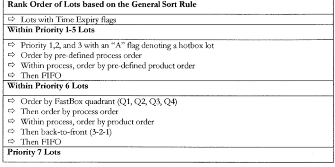
material to meet the factory's dual-focused charter. D2's General Sort Rule is summarized in Table 1. All factory workstations default to the General Sort Rule unless exceptions are put in place at specific equipment set. Exceptions, referred to as micro-policies, are commonly put into place at constraint tools, feeder-to-constraints, and workstations with known best practices that are not incorporated by the general macro-policy.
Be it a philosophy based on the Theory of Constraints (ToC), Shortest Remaining Processing Time, Critical Ratio, or other, the WIP management philosophy behind the macro-policy governs overall dispatching through the entire factory. The underlying WIP management philosophy becomes a major contributor to factory performance. As a result, major efforts have concentrated around developing and implementing macro-policies that would improve on cycle time, velocity, and output performance.
Table 1: General Sort Rule
Rank Order of Lots based on the General Sort Rule * Lots with Time Expiry flags
Within Priority 1-5 Lots
> Priority 1,2, and 3 with an "A" flag denoting a hotbox lot
4
Order by pre-defined process order4 Within process, order by pre-defined product order
> Then FIFO
Within Priority 6 Lots
4 Order by FastBox quadrant (QI, Q2,
Q3, Q4)
4 Then order by process order
4 Within process, order by product order
> Then back-to-front (3-2-1) > Then FIFO
Priority 7 Lots
The prioritization system underlying the General Sort Rule designates specific lots as having a priority from 1 (P1) to 7 (P7). P6 lots are standard production materials, while P7 lots are monitoring and test wafers used for various sustaining activities. Technology Development (T7D) and Engineering use the remaining priority levels (P1 - P5) extensively to manage the throughput time of their work. By placing the appropriate priority on their orders, they ensure fast information turnover rates for use in product development and engineering.
D2's macro-policy enables a prioritization system aimed at successfully executing to the factory's charter - technology development and engineering. In effect, the General Sort Rule allows the factory to prioritize lower volume orders, which would otherwise be overwhelmed by the higher volume, more mature production orders. This ensures that the factory responds well to its internal technology development and engineering customers, but is also responsive to shifting customer and market demand. Intel can, for example, quickly realize revenues on a hot product whose demand has just peaked. In sum, D2's General Sort Rule achieves D2's goal to develop new processes and products quickly, while at the same time providing the
market with high-end products at lower manufacturing costs. As will be seen later, however, its presence as a default dispatching policy may not be appropriate at certain equipment sets.
4.2 FastBox 3-2-1
When Intel is participating in a supply-limited market (all that can be produced is sold), two performance metrics of great importance are Output (OUTS) and Throughput Time (TPT). Maximizing OUTS has direct effect on top line revenue: greater output leads to greater revenue. Minimizing TPT is also very important, but its importance cannot be easily defined financially. Minimizing TPT increases the rate of information flow in the factory, enabling faster technology development cycles, and enhancing information about the health and performance of the factory. Moreover, minimizing TPT may mean greater responsiveness to the market as manufacturing lead times decrease.
A problem arises when we try to both maximize OUTS and minimize TPT. Loading the factory and increasing Work-in-Process (WIP) can increase output. Doing so will ensure that enough material is in the line to keep equipment busy. As long as the equipment is available and technicians qualified to operate the equipment are present, output will be maximized. Yet,
such an increase in WIP will result in increased queue times, adversely affecting TPT.
Intel addresses the output and throughput predicament via WIP management policies that have been incrementally developed and revised through the past several years. The groundwork for improved output performance has been based on Goldratt's Theory of Constraints (ToC) [Goldratt, 1992]. Great emphasis has been placed on the factory's lowest capacity equipment since lost output at the constraint is lost output for the factory. This has been accomplished by:
1. buffering the constraint with WIP as protection against variable availability of upstream equipment,
2. starting material into the line based on the need and capacity of the constraint,
3. subordinating other equipment to make sure that the constraint is fed properly and WIP is always there,
4. making sure that the constraint is always staffed with properly trained technicians, and 5. maintenance at the constraint is given the highest priority.
WIP management enhancements to improve TPT have led to the implementation of "back-to-front" lot dispatching. Known in the operations research literature as "Shortest Remaining Processing Time" (SRPT) [Wein, 1988], this strategy recommends selecting lots that are close
to completion. The farther along a lot has progressed through the manufacturing line, the more value it has accumulated and the closer it is to generating revenue. Under this policy, if a workstation runs multiple operations along the process flow, lots (jobs) at an operation closer to the end of the line are prioritized above those closer to the start of the line. At Intel, this policy is known as "3-2-1", dating back to technology generations with three metal layers - "3-2-1" was a handy rule-of-thumb for reminding manufacturing technicians of the lot dispatch policy. The implementation of "3-2-1" had a positive effect on reducing TPT, especially toward the back end of the process flow.
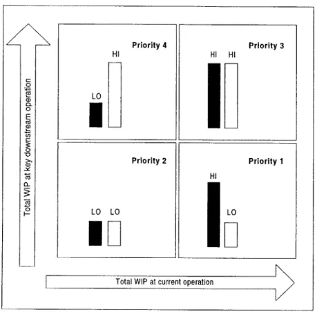
More recent work to further enhance TPT and increase OUTS has led to the formulation of the FastBox lot dispatch policy. FastBox was developed to maximize WIP velocity, while insuring that the constraint is always fed. At Intel, WIP velocity is defined as an average inventory turns metric across the factory. The ratio of the number of manufacturing activities completed to the total number of wafers yields the WIP velocity; e.g., WIP velocity of one implies the average wafer completes one activity step per day. Velocity can be increased either by reducing WIP or increasing number of activity steps performed. As a WIP management policy, FastBox targets the latter by looking at the work available at each processing operation an equipment runs, and looking at key downstream operations that this equipment feeds to see if work is needed there. Prioritization of WIP at an equipment set can best be explained with reference to Figure 5.
At a given equipment set, the amount of WIP at each operation is calculated and compared to the WIP at a key downstream operation that the equipment set feeds. The two WIP levels are denoted as either HI or LO based on a predetermined HI/LO criterion, e.g., 100 wafers. For example, those WIP queues larger than 100 wafers (the HI/LO criterion) are denoted HI, while those below are denoted LO. The darkened WIP levels in Figure 5 denote WIP levels at
the current equipment set, while the white WIP levels describe the WIP situation at key downstream operations. Under this system, an operation with HI WIP feeding an operation with LO WIP is given the highest priority. In this case, priority is given to an operation with much work that feeds an operation with little work in an attempt to move work to where it is needed most, and to keep it moving.
Priority 4 Hl LO Priority 2 LO LO
ED
Priority 3 H1 Hi I Priority 1I
LOPI
Total WIP at current operationFigure 5: FastBox
An operation with LO WIP feeding another operation with LO WIP is prioritized next (priority 2). This is to ensure that when the equipment is available, work is not moved to high WIP areas where queue times are already high. As a result, the first two priorities are given to
operations that move WIP to low WIP locations where the work can be processed as soon as possible. The lowest priority is given to those operations that do not have much WIP at the time, but are at a risk to moving work to already high WIP operations downstream. When multiple operations fall into the same FastBox quadrant, ties are broken using the "3-2-1"
C 0 C) 0 0 a) Cl) C 0
policy, thus the name "FastBox 3-2-1". Referring back to previous discussion of dispatching policies, one may see Fastbox as a variant of researched rules such as LWNQ mentioned by Lu
[1994] and Wein [1988]. As discussed earlier, these rules, and Fastbox as a variant, intend to compete with throughput maximization rules such as those based on shortest processing time.
Two key implementation considerations exist for the Fast Box rule: which equipment sets use it, and which downstream operation is chosen. In choosing which toolsets adopt Fast Box, we note certain equipment sets have substantial excess capacity owing to tool redundancy and other capacity considerations. In this case, these operations process work quickly, resulting in very short queues and low queue times. Under such situations, the FastBox policy is reduced to one dimension in which WIP at the current operation is always LO, and material is
restricted to either priority 2 or 4. If the equipment set has limited capacity and tends to build WIP, operations crossing the HI/LO WIP criterion are prioritized across both dimensions,
first based on WIP levels at the current equipment, then based on WIP levels downstream. As a result, the second key consideration leads to proper selection of downstream operations.
When looking downstream from an operation prioritized by Fastbox, it is the first downstream operation that tends to build a WIP queue (corresponding to excessively high cycle time) that should be considered when applying the FastBox policy. Simply looking at the next immediate downstream operation won't do. As will be shown later, the next immediate downstream operation might be on a high throughput tool that might demonstrate low queue times. It becomes increasingly important to select the appropriate downstream operation for consideration. Moreover, as will be described later, the amount of work between the operation being prioritized and the selected downstream operations should be considered as well in order to capture WIP traveling between these two queues.
4.3 Micro-policies
The fraction of workstations operating to a micro-policy in a given fabrication facility varies with WIP management philosophy and the stage of production lifecycle - whether it is at