Publisher’s version / Version de l'éditeur:
Interface - Journal of Roof Consultant Institute (RCI), 24, September 9, pp. 5-13,
2006-09-01
READ THESE TERMS AND CONDITIONS CAREFULLY BEFORE USING THIS WEBSITE. https://nrc-publications.canada.ca/eng/copyright
Vous avez des questions? Nous pouvons vous aider. Pour communiquer directement avec un auteur, consultez la
première page de la revue dans laquelle son article a été publié afin de trouver ses coordonnées. Si vous n’arrivez pas à les repérer, communiquez avec nous à [email protected].
Questions? Contact the NRC Publications Archive team at
[email protected]. If you wish to email the authors directly, please see the first page of the publication for their contact information.
NRC Publications Archive
Archives des publications du CNRC
This publication could be one of several versions: author’s original, accepted manuscript or the publisher’s version. / La version de cette publication peut être l’une des suivantes : la version prépublication de l’auteur, la version acceptée du manuscrit ou la version de l’éditeur.
Access and use of this website and the material on it are subject to the Terms and Conditions set forth at
Top 10 questions and answers on static vs. dynamic wind testing for
commercial roofs
Baskaran, B. A.
https://publications-cnrc.canada.ca/fra/droits
L’accès à ce site Web et l’utilisation de son contenu sont assujettis aux conditions présentées dans le site LISEZ CES CONDITIONS ATTENTIVEMENT AVANT D’UTILISER CE SITE WEB.
NRC Publications Record / Notice d'Archives des publications de CNRC:
https://nrc-publications.canada.ca/eng/view/object/?id=dafa1393-44e0-4186-823d-63c256985f4d https://publications-cnrc.canada.ca/fra/voir/objet/?id=dafa1393-44e0-4186-823d-63c256985f4d
http://irc.nrc-cnrc.gc.ca
Top 1 0 que st ions a nd a nsw e rs on st at ic
vs. dyna m ic w ind t e st ing for c om m e rc ia l
roofs
B a s k a r a n , B . A .
N R C C - 4 8 6 7 6
A version of this document is published in / Une version de ce
document se trouve dans: Interface – Journal of Roof
Top 10 Questions and Answers
on
Static vs Dynamic Wind Testing for Commercial Roofs
Bas A. Baskaran Ph.D, P.EngSenior Research Officer National Research Council Canada
1200 Montreal Road, Ottawa, ON Canada, K1A OR6
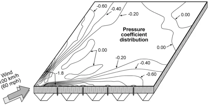
Q1: What are the attributes of wind on a roof
Wind is a random process. When it separates from the roof edges, it creates zones of suction (negative) pressure. This suction effect has two characteristics: (a) it varies from one zone of the roof to the other – spatial variations (b) it varies from one period of time to other – fluctuations with respect to time. One can distinguish the spatial variations from zones of higher to lower suctions as corner, edge and field while the time fluctuations are simplified through statistical approach by calculating mean, peak and standard deviation.
Figure 2: Pressure fluctuations at a location on a roof
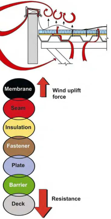
Q2: What are the attributes of roofing-response to wind?
If one views wind-induced pressure on a roof as “action”, then the “reaction” is the response of the roof. Not all roofs respond to wind in a similar manner. The response can be static or dynamic, and it depends on the assembly’s components, attachment methods, and application technologies. The new generation of mechanically attached system’s response is different compared to a conventional, fully bonded system. In mechanically attached systems1, membranes are attached at discrete points or rows. Moderate-to-strong winds will cause the membrane to lift and billow between attachment points or rows. The billow height is primarily a function of the wind load, the fastener row spacing, the load-strain modulus of the membrane, and the presence of an air/vapour barrier (retarder)in the roof system. Wind fluctuations cause the membrane to flutter, or rapidly flap up and down. The dynamic (or cyclical) loading induced by the fluttering can cause fatigue to the membrane, the membrane fasteners, the substrate on to which the membrane is fastened, or the fastener to deck engagement locations.
1 Baskaran, A. and Smith, T.L (2005), “A Guide for the Wind Design of Mechanically Attached Flexible Membrane
Figure 3: Static (Fully Bonded System) and dynamic (Mechanically Attached System) responses
Q3: What is a static test?
In a static test, roofs are subjected to constant pressure difference across the deck and water proof membrane. Normally, in the North American roofing community, FM Global (FMG) 44702 test method is considered as a static test. In that test, all roofs are subjected to a static pressure differences as shown below.
2
Figure 4: Static load cycle
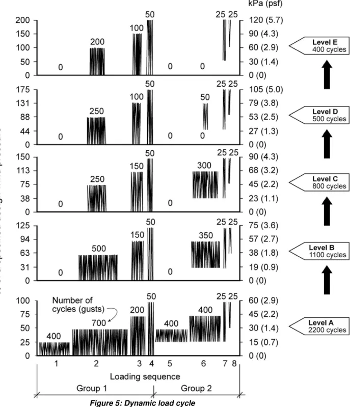
Q4: What is a dynamic test?
In a dynamic test, wind pressures are varied across the system. The intensities and magnitudes are dependent on the building’s aerodynamics and wind exposure. Normally, in the North American roofing community, the CSA A123.21-043 test method is considered as a dynamic test. In an attempt to mime Mother Nature, wind dynamics of varying intensities are induced over a roofing system. Each wind gust has a frequency of 0.5 Hz or 2 seconds.
3 CSA A123.21-04 (2004), “Standard Test Method for the Dynamic Wind Uplift Resistance of Mechanically Attached
Figure 5: Dynamic load cycle
Q5: How are test methods developed?
The development of a full-scale test procedure requires several levels of generalization of the true wind-induced effect over a roof assembly. Often, these generalizations warrant compromise from the technically sound approach to the practically acceptable procedure. The author is unaware of the level and extent of generalization of the wind induced effects used in the development the static test. Nevertheless, the development dynamic of the test involved input from all parties concerned with roofing, including researchers, manufacturers, roofing associations representing contractors, and building owners. (Refer to the acknowledgment section for the SIGDERS
consortium participants.) Six attributes for the development of a dynamic load cycle were selected from the concerns raised by the members and listed, based on priority, as follows:
1. Mimic as much as possible the true wind effects.
2. Simulate failure modes similar to those under field conditions. 3. Account for the variation in roofing components and materials. 4. Be easier to apply in a common laboratory environment.
5. Have a reasonable test-processing time of not more than a day, including setup and testing.
6. Be compatible with local building codes and wind standards.
SIGDERS consortia and CSA standardization process scrutinized the generalization conducted in the development of the dynamic wind load test procedure. Based on this vision, the CSAA123.21.04 dynamic test was published. Data from extensive wind tunnel studies of full-scale roof assemblies were used, and finite element models were developed to extrapolate the data base.
Q6: The static test takes less time. Is it beneficial?
Yes, a static test always takes less time due to the fact it is not simulating wind fluctuations. Static wind uplift rating data may be an indicator to compare two systems, whereas, its benefits for engineering design are questionable.
Q7: The dynamic test has various gusts levels. Why?
Roofs, during the life span, experience winds of varying speeds such as periods of calm winds, moderate winds and severe winds (hurricane session). As indicated under question #1, the test method should account for these wind speed variations. This is why the dynamic test has varying intensity gusts, and uses wind loads specified in the national documents such as NBCC 20054 and ASCE 7-025. Such calculated pressures are used to convert the test pressure ratios in Figure 5 rather than using an arbitrary selection.
Q8: Is there an experimental factor to convert static wind uplift ratings to
dynamic wind uplift ratings?
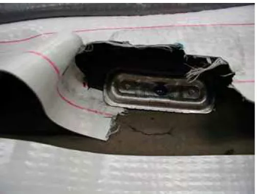
No. Systems responses are different under static and dynamic loadings. Even for a particular installation category, (say, a mechanically attached system), resistance data from a static test can be different from that of a dynamic one. Significant efforts were made under the SIGDERS consortia to develop an experimental factor to convert the static wind uplift rating into an equivalent dynamic wind uplift rating. It has been concluded, (considering the material advancements and application technologies), that use of a single conversion factor is scientifically invalid. This can further be explained by means of a ‘weakest resistance link’ chain. Components of a mechanically attached system are: deck, fasteners, plates, air/vapour barriers (retarders), insulation, and membrane. Each component offers a certain resistance to wind uplift. All resistance links should remain connected for the system to be durable and to keep the roof properly in place. Failure occurs when the wind uplift force is greater than the resistance of any one or more of these links. For example, the assembly is considered to have failed when a fastener pulls out from the deck even if the membrane and its seams are in good condition. Similarly, a system is considered failed when a seam tears under gusting wind while other components remain intact. Due to variations in resistance, the failure mode can also vary. Figure 6 shows typical examples of the difference in failure mode and wind uplift rating data between static and dynamic tests for various systems. Note that all these test were completed at the SIGDERS table setup. As shown, some systems perform similar irrespective of the test methods, while for others there are significant variations. It is worth to mention that one cannot use similar
4
NBCC. 2005. “National Building Code of Canada”, National Research Council of Canada, Ottawa, Canada.
5 ASCE. 2002. “Minimum design loads for buildings and other structures.”, ASCE Standard 7 –02, American Society
observations for other systems using the same membrane as it may have a different in application technology.
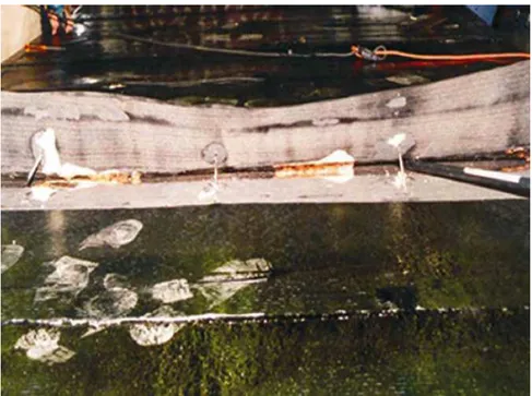
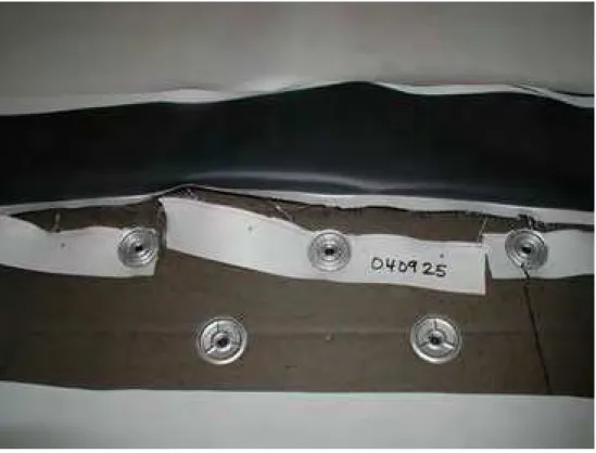
Comparison of static vs dynamic rating and failure mode of various mechanically attached systems
Fig 7.1 Failure modes of PVC systems
Dynamic test – Wind uplift rating 60 psf
Fig 7.2 Failure modes of TPO systems
Static test – Wind uplift rating 90 psf
Static test – Wind uplift rating 60 psf
Fig 7.3 Failure modes of Mod Bit systems
Static test – Wind uplift rating 135 psf
Fig 7.4 Failure modes of EPDM systems
Q9: Is there a formula to convert the wind uplift rating to wind speed?
The wind uplift rating and wind speed are different parameters; therefore one cannot use a conversion factor. Wind uplift rating obtained from testing can be used in the design process as shown below.
Q10: What is the use of a wind uplift rating in the design process?
First the rating data should be converted to resistance. By using a safety factor, divide the rating to obtain the resistance. The designer then correlates the resistance with the required design load to validate that the resistance is always higher than the load requirement. A simplified case study is presented below.
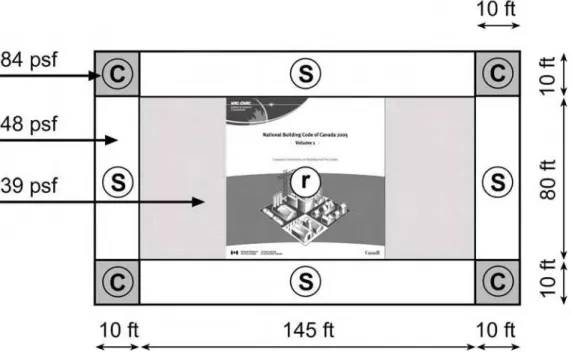
Step 1: Calculate the Design Load
Calculate the wind load for various zones (i.e., field, edge, corner) of the roof assembly in accordance with the local building code.
Figure 8: Wind Load Diagram
Step 2: Select the Roof Assembly
Use a minimum safety factor of 1.5 if the wind uplift rating of the roof assembly and components is obtained from dynamic testing. Use a safety factor of 2.0 if the uplift rating is obtained from static testing. This provides the resistance data.
Required System Rating Required System Rating from Dynamic Testing from Static Testing Corner 84 x 1.5 = 126 psf or higher 84 x 2 = 168 psf or higher Edge 48 x 1.5 = 72 psf or higher 48 x 2 = 96 psf or higher
Field 39 x 1.5 = 59 psf or higher 39 x 2 = 78 psf or higher
Step 3: Correlation
Select roof assemblies and related components with resistance data higher than the load data.
Figure 9: Correlation of resistance with load
Step 4: Generalization
In some cases, it may be economical to use a single set of components both for the edge and corner zones. In such cases, the corner zone resistance data should be applied to the edge zone (not vice versa).
Figure 10: Correlation of resistance with load - generalization
Acknowledgement
The presented research is being carried out for a consortium - Special Interest Group for Dynamic Evaluation of Roofing Systems (SIGDERS). SIGDERS was formed from a group of partners who were interested in roofing design. These partners include:
Manufacturers: Atlas Roofing Corporation, Canadian General Tower Ltd., Carlisle Syntec Incorporated,
GAF Materials Corporation, GenFlex Roofing Systems, Firestone Building Products Co., IKO Industries Ltd., ITW Buildex, Johns Manville, Sarnafil, Soprema Canada and Stevens Roofing Systems, Tremco Inc and Trufast Corporation
Building Owners: Canada Post Corporation, Department of National Defence, Public Works and
Government Services Canada.
Industry Associations: Canadian Roofing Contractors' Association, Canadian Sheet Steel Building
Institute, National Roofing Contractors’ Association and RCI, The Institute of Roofing, Water proofing, and Building Envelope Professionals.