BEHAVIOR OF REFRACTORY LININGS FOR SLAGGING GASIFIERS
by
En-Sheng Chen
B.Sc. (Eng.) (Civil), National Taiwan University (1977)
M.Sc. (Eng.) (civil), Massachusetts Institute of Technology (1982)
Submitted to the Department of
Civil
Engineering
in
Partial Fulfillment of the
Requirements of the Degree of
Doctor
of Philosophy
at the
Massachusetts Institute of Technology
May
1984
Q
Massachusetts Institute of Technology, 1984
Signature of Author
Certified by
Accepted by
Depattment of Civil
Engineering
Oral
Bu#tkozt(i*, Thesis
Supervisor
Francois M.
M.
Morel, Chairman
;AssiACL'.• ir~jiieering Departmental CommitteeOF TECHNrLOGY
JUN 2 9 1984
ArchiveS
LIBRAP.AE. 32
-BEHAVIOR OF REFRACTORY LININGS FOR SLAGGING GASIFIERS
by
En-Sheng Chen
Submitted to the Department of Civil Engineering in partial fulfillment of the requirements
for the Degree of Doctor of Philosophy in Civil Engineering, May 1984
ABSTRACT
Coal gasification in a slagging gasifier unit is an efficient process in converting coal into economic gaseous fuel. In the gasifier, the operating temperatures are high with simultaneous presence of highly corrosive slags and gases. A refractory lining system is usually adopted as a thermal barrier to maintain the high operating temperature in the gasifier and as a potective layer for the gasifier vessel against corrosion attack. The refractory linings are generally in the form of composite cyclindrical walls composed of layers of bricks, mortar joints and cooling systems. Due to critical design conditions that exist in the gasification environments, a safe and economic design of the lining system and the determination of proper operational control involve challenging engineering problems which require a thorough understanding of the lining behavior in the high temperature, highly corrosive environments.
Generally, high-AZ203 and high-Cr203 refractories have been
considered as candidate materials for the primary layers of the lining systems in the slagging gasifiers. These materials have relatively high resistance to corrosion and thermal attack. The material and systems behaviors of the linings adopting these materials are quite complex, and a thorough behavioral understanding is essential for achieving an optimal design and for the determination of proper
operational schemes. It is the purpose of the present work to develop predictive material models and analysis capability to study the lining
system behavior in gasification environment, and through
analytical/numerical simulations to reach specific guidelines for the design and the operation of the lining systems.
Temperature dependent material models are developed to represent the thermophysical and thermomechanical behaviors of the candidate refractory materials. Special emphasis is on the development of a
time-independent, damage-type constitutive model for brittle materials. This model adopts the bounding surface concept in stress space to characterize material strengths in various stress paths, and, in
-3-conjunction with the adoption of a damage parameter
in
strain space, to
represent the material degradation due to damage accumulation. This
model is
general, and has the capability to predict the material
response to multiaxial, nonproportional, and cyclic loads.
In
addition to the time-independent constitutive model, a creep
model, a conductivity model for cracked media, and polynominal
representations of thermophysical properties are proposed for the
candidate materials. A special finite element program incorporating
these models is
developed. The computer package developed provides a
unique and powerful tool for the thermomechanical analysis of
refractory lining systems.
A predictive corrosion model is
proposed to study the long-term
corrosion process of lining systems in
slagging gasifiers. The
corrosion process is
considered as the interactive results of different
corrosion mechanisms (dissolution and spalling), and temperature
distribution in
the lining systems. Based on this model, sensitivity
study, including various lining materials, lining geometries, and
operating conditions, is
performed to identify the important factors
characterizing the long-term corrosion behavior of the linings.
In
high-temperature environments, the transient heat-up period
represents a critical structural stage in
the lining system. During
thit period the linings experience severe structural conditions, due to
the high temperature gradient, high confining stresses, and the less
effective stress relaxation. A proper design and operational control
in
reducing the damage in
the lining during the heat-up periods is
of
great concern. In
the present work, the thermomechanical behavior of
linings with various combinations of lining material and lining
geometry (single layer, multiple layer, and the adoption compressible
layers and expansion joints)
,
and under various heating schemes
(various combination of different heating rates, and holding periods)
is
studied. The results from these studies provide a basis for the
determination of proper design and operational control for the linings
in slagging gasification.
Finally, based on the findings from the thermomechanical and
corrosion analyses, recommendations are made for the design and
operation of reliable and durable lining systems.
Thesis Supervisor:
Dr. Oral Buyukuzturk
-4-ACKNOWLEDGEMENTS
The author wishes to express his sincere appreciation to Professor
0. Buyukozturk for his supervision of this thesis, his continued
interest and encouragement, and valuable suggestions throughout the course of this work. His pioneering efforts in the development of a general thermomechanical analysis methodology for structural systems
with brittle materials have contributed to a great extent to this
research.
The author would also like to acknowledge the support, encouragement and cooperation of a number of individuals. In
particular, the author would like to thank Mr. R. Bradley of Oak Ridge National Laboratory for his moral and intellectual support, and
continuous encouragement; Mr. W. T. Bakker of Electric Power Research Institute; Professor T. D. McGee of Iowa State University; Mesrs. M. E. Washburn, K. R. Costen and L. Trostel of Norton Company for kindly
sharing their valuable experience and spending many hours in discussing problems of this research with me; Professors D. Veneziano, J. H. Slater and V. C. Li who were the thesis committee members of the author. The author particularly expresses his appreciation to Professors D.
Veneziano and J. H. Slater for their helpful criticisms and countless
help in reading and improving this thesis.
The author wishes to extend his gratitude to Mrs. S. L. Weiner, for her excellence, expertise and patience in typing the manuscript, and for her numerous and consistent help.
Finally, the author would like to express his deepest appreciation to his parents and his wife, Judy, for their continuous support and encouragement throughout the years of his education.
This work was supported by the U.S. Department of Energy through Advanced Research and Technology Development Fossil Energy Materials Program, under contract No. 7862.
-5-TABLE OF CONTENTS Page Title Page 1 Abstract 2 Acknowledgements 4 Table of Contents 5 List of Figures 9 List of Tables 19 List of Symbols 20 Conversion Factors 26 Chapter 1 INTRODUCTION 27
§1.1 Coal Gasification - A Review 27
§1.2 Research Problems Associated with the Lining
of Slagging Gasifiers 32
§1.3 Review of Previous MIT Work 36
§1.4 Current Research Objectives and Approach 38
§1.5 Organization 41
Chapter 2 LINING SYSTEM AND LINING MATERIALS FOR
SLAGGING GASIFIERS 43
§2.1 Gasification Environment 43
§2.2 Factors Destructive to the Refractory Linings
Systems 47
§2.3 Conceptual Design of a Lining System 55
-6-Page Chapter 3 MATERIAL BEHAVIOR AND MATERIAL MODELING 67
§3.1 Introduction 67
§3.2 Thermophysical Properties 68
§3.2.1 Thermal Conductivity 68
§3.2.2 Density and Specific Heat 74
§3.2.3 Coefficient of Thermal Expansion 78
§3.3 Modeling of the Time-Independent
Thermomechanical Behavior 83
§3.3.1. 90% Alumina Refractory, 80% Chromia
Refractory and Concretes 83
§3.3.2 SiC Refractory and Steel 113
§3.4 Creep 114
Chapter 4 SLAG CORROSION OF REFARCTORY LININGS 125
§4.1 Introduction 125
§4.2 Corrosion Mechanisms 126
§4.3 Corrosion Model 140
§4.3.1 Relationship between Hot-Face Temperature
and Lining Thickness 143
§4.3.2 Proposed Corrosion Model 150
§4.3.3 Residual Lining Thickness 151
§4.4 Y(t) as a Random Process 160
§4.5 Approximate Model 168
Chapter 5 THERMOMECHANICAL ANALYSIS OF LINING SYSTEMS
BY THE FINITE ELEMENT METHOD 171
§5.1 Introduction 171
-7-Page
§5.3 Stress Analysis (Displacement Method) 182
§5.4. Heat Transfer - Stress Resultant Interaction 191
§5.4.1 Thermal Expansion 192
§5.4.2 Conductivity Model for Cracked Media 198
§5.5 Joint Modeling 203
§5.5.1 Joint Strength 203
§5.5.2 Joint Element 206
§5.6 Slag Penetration and Spalling 208
§5.6.1 Slag Penetration 208
§5.6.2 Spalling 209
Chapter 6 LINING BEHAVIOR IN TRANSIENT HEATING PROCESS 211
§6.1 Introduction 211
§6.1.1 Assumptions 213
§6.1.2 Materials and Lining Configurations 215
§6.1.3 Operational Schemes 215 §6.1.4 Failure Modes 219 §6.1.5 Organization 220 §6.2 Heating Scheme (1) 220 §6.2.1 Heating Rate = 50°F/hr 221 §6.2.2 Heating Rate = 150"F/hr 239 §6.3 Heating Scheme (2) 241 §6.4 Heating Scheme (3) 254 §6.5 Summary 263
-8-Page
Chapter 7 DESIGN AND OPERATIONAL RECOMMENDATIONS 266
§7.1 Design 266
§7.1.1 Material Selection 267
§7.1.2 Lining Configurations 269
§7.2 Operation 271
Chapter 8 SUMMARY, CONCLUSIONS AND RECOMMENDATION
FOR FUTURE RESEARCH 274
§8.1 Summary 274
§8.2 Conclusions 279
§8.3 Recommendations for Future
Research 282
REFERENCES 284
APPENDIX 292
A.1 Appendix I: Program SRLT 293
A.1.1 List of Program 294
A.1.2 Example of Input File 302
A.1.3 Example of Output File 303
A.2 Appendix II: Program PARL 307
A.2.1 List of Program 308
A.3 Appendix III: 2-D Finite Element Heat
Transfer Analysis Using Triangle Element 310 A.4 Appendix IIII: Description of Program TARL 315
-9-LIST OF FIGURES
Figure No. Page
1.1 Coal Gasification Process 30
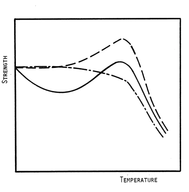
1.2 Schematic of Refractory Brick Lining System 34 2.1 Typical Uniaxial Strength - Temperature Curves 48 2.2 Cracking and Spalling of Refractory Lining at
Advanced Stage 50
2.3 Refractory Lining Life Curve 50
2.4 Mole Percentage of Chemical Composition in Slag-Refractory System (99% A1203 Refractory
Exposed to High Iron Oxide Coal Slag) 52
2.5 Mole Percentage of Chemical Composition in Slag-Refractory System (90% A1203 Refractory
Exposed to High Iron Oxide Coal Slag) 52
2.6 Mole Percentage of Chemical Composition in Slag-Refractory System (60% A1203 Refractory
Exposed to High Iron Oxide Coal Slag) 53 2.7 Mole Percentage of Chemical Composition in
Slag-Refractory System (80% Cr203 Refractory
Exposed to High Iron Oxide Coal Slag) 53
2.8 Corrosion of Refractories 54
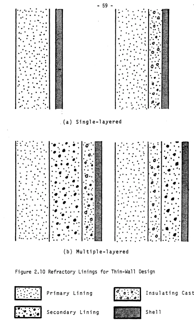
2.9 Refractory Linings for Thick-Wall Design 57 2.10 Refractory Linings for Thin-Wall Design 59 2.11 (a) Cooper Plate Cooled Wall in Slagging Coal
Gasifier 60
(b) Studded Membrane Wall in Slagging Coal
Gasifier 61
2.12 Test Furnace for Rotating Corrosion Test in
Molten Slag 63
3.1 Thermal Conductivity (Ks) vs. Temperature (T)
Relationship for 90% A0203 + 10% Cr203 Refractory 70
3.2 Thermal Conductivity (Ks) vs. Temperature (T) Relationship for 80% CrqO + 20% MgO Refractory
- 10
-Figure No. Page
3.3 Thermal Conductivity (Ks) vs. Temperature (T)
Relationship for SiC Refractory 73
3.4 Thermal Conductivity (Ku) vs. Temperature (T)
Relationship for H2 (Hydrogen) Gas 75
3.5 Product of Density (P) and Specific Heat (C )
vs. Temperature (T) Relationshp for 90% A-2 3 +
10% Cr203 Refractory 76
3.6 Product of Density (P) and Specific Heat (C )
vs. Temperature (T) Relationshp for 80% Cr203 +
20% MgO Refractory 77
3.7 Product of Density (P) and Specific Heat (Cp)
vs. Temperature (T) Relationshp for SiC Refractory 79 3.8 Linear Expansion vs. Temperature Relationship for
90% Ak203 + 10% Cr203 Refractory 80
3.9 Linear Expansion vs. Temperature Relationship for
80% Ak203 + 20% MgO Refractory 81
3.10 Linear Expansion vs. Temperature Relationship for
SiC Refractory 82
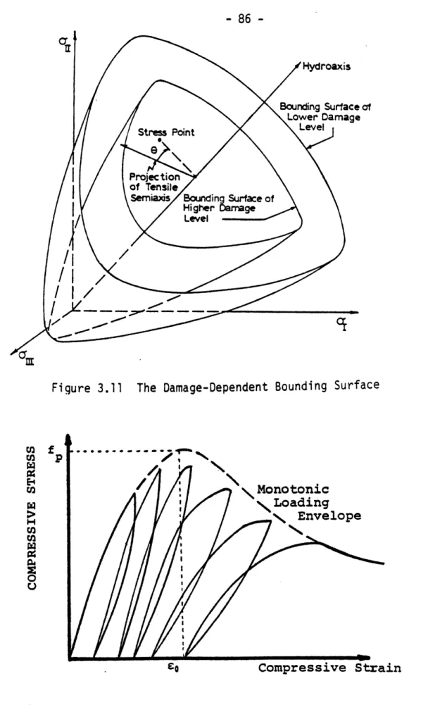
3.11 The Damage-Dependent Bounding Surface 86
3.12 Stress-Strain Relationship for Ceramic Material
in Uniaxial Compression 86
3.13 The Measure of Normalized Distance D 89
3.14 Comparison of Model Prediction with Monotonic
Biaxial Compression Test Data of Concrete 101 3.15 Comparison of Model Prediction with Monotonic
Triaxial Compression Test Data (8 = 60o) of
Concrete 102
3.16 Comparison of Model Prediction with Monotonic
Triaxial Compression Test Data (11 = constant)
of Concrete 103
3.17 Comparison of Model Prediction with Cyclic
Uniaxial Compression Test Data of Concrete 104
3.18 Comparison of Model Prediction with Cyclic
Biaxial Compression Test Data (Generalized
- 11
-Figure No. Page
3.19 Comparison of Model Prediction with Monotonic Uniaxial Compression Test Data of 90% Ak203
+ 10% Cr203 Refractory at Room Temperature 107
3.20 Uniaxial Compressive Strength vs. Temperature for 90% A1203 + 10% Cr203 Refractory (without and
with slag saturation) 108
3.21 Uniaxial Compressive Strength vs. Temperature
for 50% Ak203 Insulating Refractory Concrete 109 3.22 Comparison of Model Prediction with Monotonic
Uniaxial Compression Tests Data of 90% A-203
+ 10% Cr203 Refractory at 2000°F 111
3.23 Comparison of Model Prediction with Monotonic Uniaxial Compression Tests Data of 90% AZ203
+ 10% Cr203 Refractory at 2500*F 112
3.24 Typical Creep Curve 115
3.25 Strain Hardening Model and Time Hardening Model 115 3.26 Comparison of Model Prediction with Creep
Data at 2200:F and 2460°F 123
3.27 Comparison of Model Prediction with Creep
Data at 2732:F 124
3.28 Comparison of Model Prediction with Creep
Data at 2500OF 124
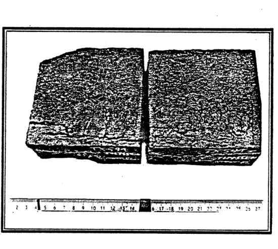
4.1 Cracking of Refractory Bricks in Slagging
Gasifier 130
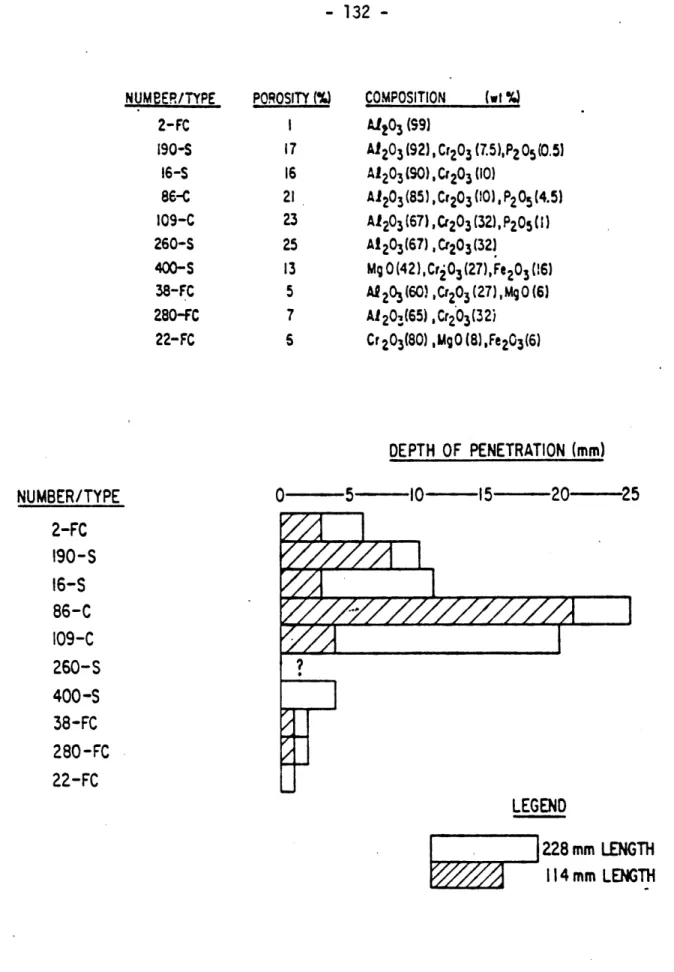
4.2 Approximate Depths (as measured from the final position of the slag-refractory interface)
of Slag Penetration into Refractories 132 4.3 Estimation of Slag-Penetrated Zone in a Lining 133 4.4 Estimation of Critical Temperature of Slag
Penetration into 90% A0203 Refractory (U.S.
Coal Slag System) 134
4.5 Estimation of Critical Temperature of Slag
Penetration into 80% Cr203 Refractory (U.S.
- 12
-Figure No. Page
4.6 Effects of Slag Penetration on Initial
Young's Modulus of 90% A2-203 Refractory 137
4.7 Effects of Slag Penetration on Creep
Behavior of 90% AZ203 Refractory
(Uniaxial stress = 4865 psi) 138
(a) Before Slag Penetration
(b) After Slag Penetration
4.8 Effects of Slag Penetration on Thermal
Conductivity of 90% A1203 Refractory 139
4.9 Schematic of Single-Layer Lining System
and Boundary Conditions 141
4.10 Hot-Face Temperature vs. Lining Thickness
Relationship (ro = 60") for 90% A0203
Refractory Lining 146
4.11 Hot-Face Temperature vs. Lining Thickness Relationship (ro = 108") for 90% A0203
Refractory Lining 147
4.12 Hot-Face Temperature vs. Lining Thickness
Relationship (ro = 180") for 90% A0203
Refractory Lining 148
4.13 Hot-Face Temperature vs. Lining Thickness Relationship (ro = 108") for 80% Cr203
Refractory Lining 149
4.14 Residual Lining Thickness vs. Time for
90% A203 Refractory Lining (h = 0.1 Btu/
hr-in2-*F, TI = 3000*F) 153
4.15 Residual Lining Thickness vs. Time for
90% A203 Refractory Lining (h = 1.0 Btu/
hr-in2-*F, T1 = 3000*F) 154
4.16 Residual Lining Thickness vs. Time for
90% A203 Refractory Lining (h = 10.0 Btu/
hr-in2-*F, Ti = 3000*F) 155
4.17 Residual Lining Thickness vs. Time for
80% Cr203 Refractory Lining (h = 0.1 Btu/
hr-in2-*F, T1 = 3000*F) 156
4.18 Residual Lining Thickness vs. Time for
80% Cr203 Refractory Lining (h = 1.0 Btu/
- 13
-Figure No. Page
.4.19 Residual Lining Thickness vs. Time for
80% Cr203 Refractory Lining (h = 10.0 Btu/
hr-in2-°F, T1 = 30000F) 158
4.20 Residual Lining Thickness vs. Time for 90% A203 Refractory Lining (h = 1.0 Btu/
hr-in2- F, T1 = 2800°F) 161
4.21 Mean and Standard Deviation of Lining Thickness vs. Time for 90% A•203 Refractory Lining
(h = 1.0 Btu/hr-in2-*F, T1 = 3000°F) 165 4.22 Mean and Standard Deviation of Lining Thickness
vs. Time for 80% Cr203 Refractory Lining
(h = 1.0 Btu/hr-in2- F, T1 = 3000*F) 166 4.23 Mean and Standard Deviation of Lining Thickness
vs. Time for 90% A-203 Refractory Lining
(h = 1.0 Btu/hr-in2- F, T1 = 2800*F) 167 4.24 Comparison of Lining Thickness Predictions from
Approximation Model and Exact Model 170
5.1 Finite Element Representation of Domain of
Interest in A Field Problem 173
5.2 Triangular Element with Linear Interpolating
Function 180
5.3 Four-Triangle Quadrilaterial Element 180
5.4 One-Dimensional Heat Transfer Problem Through
a Wall 183
5.5 Finite Element Representation of the Wall 183
5.6 (a) Comparison of Precictions for the Temperature
History (x = 0.0) 183
(b) Comparison of Precictions for the Temperature
History (x = 1.0) 184
(c) Comparison of Precictions for the Temperature
History (x = 4.0) 184
5.7 Two-Dimensional Heat Transfer Problem Through a
Plate 185
- 14
-Figure No. Page
5.9 Comparison of Predictions For the Temperature
History 186
5.10 A Generalized Two-Dimensional Thermomechanical
Problem through a Cyclindrical Wall 194
5.11 Temperature Distribution Through the Wall
Thickness 195
5.12 Comparison of Finite Element vs. Analytical
Predictions for Stress Distribution 195
5.13 (a) Test Specimen and Test Conditions 196
(b) History of Axial Strain 196
(c) Comparison of Model Precition of Axial
Stress History with Test Data 197
5.14 Post-Cracking Strain in Tensile Stress-Strain
Curve 199
5.15 Coordinate System Associated with Crack Orientation 199
5.16 Rectangular Brick with Edge Cracked Zone 202
5.17 (a) Temperature Contours at 0.2 hour 204
(b) Temperature Contours at 1.0 hour 205
5.18 Failure Envelope for Joint Interface 207
5.19 Finite Element Modeling of Failure Zone 210
6.1 Potential Failure Modes in a Lining System 212
6.2 Schematic of a Refractory Lining System 212
6.3 Boundary Conditions for Half-Brick (Shaded Zone
in Fig. 6.2) used in the Analysis 212
6.4 Hot-Face Heating Schemes and Cold-Face Cooling
Schemes 217
6.5 Temperature and Stress Distributions
(Simulation No. C-i, Time=2.0 hrs,
Hot-FAce Temperature=177°F) 225
6.6 Temperature and Stress Distributions (Simulation No. C-2, Time=12.0 hrs,
- 15
-Figure No. Page
6.7 Temperature and Stress Distributions
(Simulation No. C-3, Time=12.0 hrs,
Hot-Face Temperature=677"F) 226
6.8 Temperature and Stress Distributions (Simulation No. C-4, Time=15.0 hrs,
Hot-Face Temperature=827"F) 226
6.9 Temperature and Stress Distributions
(Simulation No. C-5, Time=10.0 hrs,
Hot-Face Temperature=577°F) 227
6.10 Temperature and Stress Distributions (Simulation No. C-6, Time=10.0 hrs,
Hot-Face Temperature=577°F) 227
6.11 Temperature and Stress Distributions (Simulation No. C-7, Time=7.5 hrs,
Hot-Face Temperature=452*F) 228
6.12 Temperature and Stress Distributions (Simulation No. C-8, Time=7.5 hrs,
Hot-Face Temperature=452"F) 228
6.13 Temperature and Stress Distributions (Simulation No. C-9, Time=12.5 hrs,
Hot-Face Temperature=702*F) 229
6.14 Temperature and Stress Distributions (Simulation No. C-10, Time=12.5 hrs,
Hot-Face Temperature=702°F) 229
6.15 Temperature and Stress Distributions (Simulation No. C-11, Time=10.0 hrs,
Hot-Face Temperature=6770F) 230
6.16 Temperature and Stress Distributions (Simulation No. C-12, Time=15.0 hrs,
Hot-Face Temperature=8270F) 230
6.17 Temperature and Stress Distributions (Simulation No. C-13, Time=10.0 hrs,
Hot-Face Temperature=577°F) 231
6.18 Temperature and Stress Distributions (Simulation No. C-14, Time=10.O hrs,
16
-Figure No. Page
6.19 Temperature and Stress Distributions
(Simulation No. C-15, Time=12.5 hrs,
Hot-Face Temperature=702°F) 232
6.20 Temperature and Stress Distributions
(Simulation No. C-16, Time=12.5 hrs,
Hot-Face Temperature=702°F)
232
6.21 Temperature and Stress Distributions
(Simulation No. C-17, Time=10.0 hrs,
Hot-Face Temperature=577'F) 233
6.22 Temperature and Stress Distributions
(Simulation No. C-18, Time=10.0 hrs,
Hot-Face Temperature=577°F) 233
6.23 Temperature and Stress Distributions
(Simulation No. C-19, Time=10.0 hrs,
Hot-Face Temperature=577°F) 234
6.24 Temperature and Stress Distributions
(Simulation No. C-20, Time=10.0 hrs,
Hot-Face Temperature=577°F) 234
6.25 Temperature and Stress Distributions
(Simulation No. C-21, Time=10.0 hrs,
Hot-Face Temperature=577"F) 235
6.26 Temperature and Stress Distributions (Simulation No. C-22, Time=10.O hrs,
Hot-Face Temperature=577°F) 235
6.27 Temperature and Stress Distributions
(Simulation No. C-23, Time=12.5 hrs,
Hot-Face Temperature=702*F) 236
6.28 Temperature and Stress Distributions
(Simulation No. C-24, Time=12.5 hrs,
Hot-Face Temperature=702°F) 236
6.29 Temperature and Stress Distributions
(Simulation No. C-25, Time=12.5 hrs,
Hot-Face Temperature=702°F) 237
6.30 Temperature and Stress Distributions
(Simulation No. C-26, Time=12.5 hrs,
- 17
-Figure No. Page
6.31 Temperature Histories (Case CH-1) 243
6.32 Histories of Maximum Tensile Stress in Steel
Shell (Case CH-1) 244
6.33 Histories of Maximum Compressive Stress
in Compressible Layer (Case CH-1) 244
6.34 Temperature and Stress Distributions (Simulation No. CH-1, Time = 60.0 hr,
Hot-Face Temperature = 677°F) 245
6.35 Temperature and Stress Distributions
(Simulation No. CH-1, Time = 90.0 hr,
Hot-Face Temperature = 9777F) 245
6.36 Temperature and Stress Distributions (Simulation No. CH-1, Time = 123.0 hr,
Hot-Face Temperature = 1427"F) 246
6.37 Temperature and Stress Distributions
(Simulation No. CH-1, Time = 150.0 hr,
Hot-Face Temperature = 1577"F) 246
6.38 Temperature and Stress Distributions
(Simulation No. CH-1, Time = 210.0 hr,
Hot-Face Temperature = 2177'F) 247
6.39 Temperature and Stress Distributions (Simulation No. CH-1, Time = 216.0 hr,
Hot-Face Temperature = 2477"F) 247
6.40 Temperature Histories (Case CH-2) 250
6.41 Histories of Maximum Tensile Stresses in
Steel Shell and SiC Layer (Case CH-2) 251 6.42 Histories of Maximum Compressive Stresses
in Compressible Layer (Case CH-2) 251
6.43 Expansion Joint between Bricks 253
6.44 Width of Expansion Joint (Case CH-2) 253 6.45 Temperature and Stress Distributions
(Simulation No. CH-2, Time = 30.0 hr,
- 18
-Figure No. Page
6.46 Temperature and Stress Distributions (Simulation No. CH-2, Time = 60.0 hr,
Hot-Face Temperature = 677°F) 255
6.47 Temperature and Stress Distributions (Simulation No. CH-2, Time = 90.0 hr,
Hot-Face Temperature = 977*F) 255
6.48 Temperature and Stress Distributions (Simulation No. CH-2, Time = 126.0 hr,
Hot-Face Temperature = 1577°F) 256
6.49 Temperature and Stress Distributions (Simulation No. CH-2, Time = 180.0 hr,
Hot-Face Temperature = 18770F) 256
6.50 Temperature and Stress Distributions (Simulation No. CH-2, Time = 210.0 hr,
Hot-Face Temperature = 2177°F) 257
6.51 Temperature and Stress Distributions
(Simulation No. CH-2, Time = 216.0 hr,
Hot-Face Temperature = 2477'F) 257
6.52 Temperature Histories (Case VH-1 to VH-4) 259
6.53 Histories of Maximum Tensile Stresses in
Steel Shell and SiC Layer (Cases VH-1 to VH-4) 260
6.54 Histories of Maximum Compressive Stresses in
Compressible Layer (Cases VH-1 to VH-4) 260 6.55 Temperature and Stress Distributions
(Simulation No. VH-1, Time = 192.0 hr,
Hot-Face Temperature = 2477°F) 261
6.56 Temperature and Stress Distributions
(Simulation No. VH-2, Time = 184.0 hr,
Hot-Face Temperature = 2477°F) 261
6.57 Temperature and Stress Distributions
(Simulation No. VH-3, Time = 160.0 hr,
Hot-Face Temperature = 2477°F) 262
6.58 Temperature and Stress Distributions
.(Simulation No. VH-4, Time = 148.0 hr,
- 19
-LIST OF TABLES
Table No. Page
2.1 Slag Composition for Rotating Tests 64
2.2 Summary of the Results from Corrosion Tests 65 6.1 Lining Configurations used in the Analysis 216 6.2 Predicted Failures for the Cases Studied
(Constant heating Rate = 50*F/hr) 222
6.3 Predicted Failures for the Cases Studies
- 20 -LIST OF SYMBOLS Chapter 3 A,a,b,n,To AL,Au,~i a T Cp D E C c e.. ,de. e..,de* e e e ,de.. ij 13 p p e. ,de F Fl,Fl,max fp
model parameters in creep model
model parameters in time-independent constitutive model
temperature shift factor specific heat
normalized distance Young's modulus
deviatoric creep strain tensor, and its increment
equivalent deviatoric creep strain
deviatoric strain tensor, and its increment
deviatoric strain due to elastic response, and its increment
deviatoric strain due to plastic response, and its increment
bounding surface
normalization factor, and its maximum value material strength in uniaxial compression
generalized elastic shear modulus
generalized plastic shear modulus
H*
11,dl 1,1,max
J2,J3
generalized modulus between dD and dK
first stress invariant, its increment, and its maximum value
- 21
-deviatoric creep function
V J K,dK,Kmax kg KR,Ku ks Kt R r Rg Sij,dSij T t, At a
P
182
Cij
volumetric creep function
damage parameter, its increments, and its maximum value
thermal conductivity of gas
associated K value at the beginning of recent loading and unloading process, respectively
thermal conductivity of solid tangent bulk modulus
distance of bounding surface from the hydroaxis
along Sij direction
distance from the projection of current stress
point on the deviatoric plane to the hydroaxis universal gas constant
deviatoric stress tensor, and its increment temperature
time parameter, and its increment coefficient of thermal expansion shear compaction-dilatancy factor
shear compaction factor shear dilatancy factor
creep strain tensor
volumetric creep strain
i j,dEij
skk( v) ,d'kk, 'v
strain tensor, and its increment
volumetric strain, its increment, and its plastic component
- 22 -dco dkd kk, kk
P
Vc Y ,dYP 0 0ai
j, daI
aI, I I, I I I A ad To,d o Chapter 4 A,B,To ai Dc Dp Eo FX h ks mXvolumetric strain increment due to isotropic and deviatoric stress/strain increments, respectively associated axial strain to fp in uniaxial
compressive load Lame's constants
Poisson's ratio
Poisson's ratio of creep
density of material
plastic octahedral shear strain, and its increment
angle between projections of position vector of
principle stress and that of any tensile
semi-axis on deviatoric plane
stress tensor, its increment, and its
principal value
stress increment in ith principal direction octahedral shear stress, and its increment
parameters of corrosion model
parameters of conductivity model
depth of corrosion
depth of slag penetration initial Young's modulus
distribution function of random variable X coefficient of heat convection
thermal conductivity of solid
- 23
-r
r
oT
TcTH
T1 T2 tVX
Y,Yo aax
At
6
Chapter 5
Bib
C
Cp
D,
Di
._UCE. *,.CRStrain-displacement transformation matrix of ith
element
body force vector
heat capacity matrix
specific heat
material rigidity matrix, and that associated
with element
i
material conductivity matrix of uncracked medium,
of cracked medium at local coordinate system, and
of cracked medium at global coordinate system
radius
inner radius of gasifier
temperature
critical temperature for slag penetration
hot-face
temperature
temperature in
the gasifier
cold-face control temperature
time parameter
coefficient of variation of random variable X
lining thickness, and its initial value
mean occurrence rate in unit time
generalized normal distrubition
standard deviation of random variable X
the interval between two adjacent events
Direc delta
24 -F Fi
f,f j
fT
H h KKs
kx,ky,kn kCR kg N,Ni P T,T,To,T T i i T ,Tn TRTn,j t,At X,Y,Z u,u ,ui ~n "~n Va-9~
nodal force vector
concentrated load at point
-generalized force vector, and its value at jth
time step
boundary traction vector
coordinate transformation matrix
coefficient of heat convection
system assemblage stiffness matrix heat conductivity matrix
thermal conductivity in x and y directions, and in the direction normal to the boundary
of a domain
equivalent thermal conductivity of a cracked medium
thermal conductivity of gas
interpolating function, and that associated with
ith element
heat supply vector
temperature, its prescribed value, its initial
value, and ambient temperature
temperature in ith element, and temperature vector
at nodes of ith element
temperature vector at nodes of a system, and its
value at jth time step
time parameter, and its increment
system coordinates
displacement vector, its values at nodes, and its values at the nodes of ith element
crack volume fraction
strain vector, and that associated with ith
- 25
-el,
La i i i ill
r2a
ewoftan
Ae <initial tensile strain at crack formation, and
post-failure strain
initial strain vector of ith element, and its
component due to system initial state, creep
effets, and temperature effects, respectively
domain of field problem
density of material
boundary on which temperature is
specified
boundary on which the convective heat loss
is
specified
stress vector, and that associated with ith
element
normal stress over joint interface
shear stress over joint interface
strain increment
functional representation of a field problem
Chapter 6
E
L,W
X,Y,Z
Young's modulus of compressible material
length and width of expansion joint
system coordinates
- 26 -CONVERSION FACTORS English to SI Conversion Length: Mass: Temperature: Density: Pressure, Stress Specific Heat: Thermal Conductivity: in = 25.4 mm lb = 435.9 g ("F) = (9/5) T (@C) + 320F (°F) = (9/5) T (*K) - 459.7"F lb/in3 = 2.768 x 10⁻² g/mm3 lb/in2 (PSI) = 6895 Pa (N/m2) Btu/lb-°F = 1.055 Cal/g-*C 1 Btu/hr-in-°F = 2.077 x 10⁻² Watt/mm-°K
Prefixes most often used with SI units
109 giga 106 mega 103 kilo 10-3 milli 10-6 micro Parameter
CHAPTER
1
INTRODUCTION
§1.1
COAL GASIFICATION - A REVIEWCoal gasification is
the process of manufacturing gas from coal by
heating the coal while reacting it
with air, hydrogen, steam, and other
various mixtures. The early process of producing coal-gas can be
traced back to late 18th century when the gas was obtained by heating
coal in
the absence of air
[69].
In
the early 19th century, when
coal-gas producers started distributing their product for lighting in
London, it
became widely adopted in
Europe and U.S. In
fact, nearly
every major city in
the eastern U.S. once had its gashouse where gas
was manufactured for lighting and cooking.
The early methods of coal gasification involved a destructive
distillation process and a gasification process
[69j.
In
the
distillation process, the coal was heated until it
decomposed
chemically, releasing gas with a heating value of from 475 to 560
Btu/cft (B.T.U. per cubic foot). In
this step over
70
percent of the
original coal remained as a solid residue, and as a result, a second
stage gasification process was adopted to further utilize the coal.
In
the gasification process the solid residue reacted with air, oxygen,
and steam to produce a gas consisting essentially of a mixture of
hydrogen and carbon monoxide. The heating value of this final gas was
only about 300 Btu/cft.
-- 28
-The technology for producing gas from coal has improved
substantially since the 19th century. The use of coal-gas declined
after World War II due to the emergence of low-cost, high heating-value(1000 Btu/cft) natural gas. Natural gas is
clean, easy to distribute
by pipelines, and convenient to use, and therefore has become the
preferred candidate for residential and commercial use.
In
recent years the shortage of natural gas and petroleum made the
prospect of commercial production of synthetic fuels from coal
attractive once again. In
the United States, for example, the energy
generated by the use of available coal would exceed that of all forms
of petroleum and natural gas combined. With the improved gasification
technology for producing high-Btu gas and improved technology for
building durable gasifier vessels, the installation of commercialized
gasification plants seems feasible.
In
general, there are two broad categories of coal gasification:
low and medium-Btu gasification (200 ~ 400 Btu/cft), and high-Btu
gasification (about 1000 Btu/cft) [64J. The low and medium-Btu
gasification processes inexpensively produce gases with carbon monoxide
and hydrogen. However, gases produced this way can be used
economically only on site, either for electric power generation or by
industrial plants. On the other hand, high-Btu gasification canproduce gases consisting mainly of methane, which can be distributed
economically to consumers via the same pipelines used to deliver
natural gas. They are considered as a substitute for natural gas (SNG)
accordingly. Furthermore, the high-Btu gasification process has
potential, with further processing of its by-products, for providing
industrial feedstocks for the manufacture of other synthetics.
- 29
-Several approaches have been proposed for high-Btu gas
production. The most updated technologies, which employ the concept of "hydrogasification" and the process of "shift conversion" and
"methanation", can efficiently produce high-Btu gases with minimal gas and heat loss [32,641. These processes can be summarized in the
following major steps (Fig. 1.1).
(1) Gasification process:
(a) Hydrogasification: The coal is initially reacted
with a hydrogen-rich gas to form substantial amounts of methane directly:
2CHO.8 + 1.2 H2 * CH4 + C C + 2H2 * CH4
(b) Oxygen-gasification: Some of the coal is burned to supply the required heat for the reaction process:
C + 02 + CO2
(c) Steam-gasification: The reaction takes place
at a relatively high temperature (above 2000*F) to produce hydrogen and carbon oxides:
C + H20 + CO + H2
(2) Shift conversion process: The amount of methane in crude gas produced from the gasification process is low and further conversion of the crude gas is necessary to increase the methane content (methanation). To provide the required
- 30
-STEAM
H
2SLAG
- 31
-hydrogen in the methanation process, the process termed shift conversion is performed by interacting crude gas with steam:
CO + H20 + CO2 + H2
(3) Methanation process: The crude gas is further reacted with hydrogen to produce more methane:
CO + 3H2 + CH4 + H20
During the above mentioned processes, some intermediate steps such as gas/tar clean up and gas purification, are required to achieve the necessary steps. The above mentioned processes of coal gasification are outlined in Fig. 1.1 [32). For more details the reader may refer to Refs. 32 and 64.
In addition to the above outlined chemical processes, the coal gasification processes also involve various mechanical systems [32,69). These mechanical systems can be classified in several ways: by the method of supplying heat for the gasification reaction (internal heating or external heating); by the method of achieving contact between the reactants (fixed bed, fluidized bed, entrained bed, or molten bath bed); by the flow of reactants (current or counter current); and by the method of residue removal (slagging or
non-slagging). Briefly, in a fixed bed system a grate supports lumps of coal through which the steam or hydrogen is passed; in a fluidized bed system gas flows through the coal, producing a lifting and boiling effect; in an entrained bed system the coal particles are transported in the gas prior to introduction into the reactor; and in a molten bath bed system the coal particles and gas are dispersed in a liquid.
- 32
-Non-slagging (dry-ash) gasifiers have been used for a long time. The non-slagging gasifier usually operates at a relatively low
temperature (less than 2000°F); in these gasifiers, the non-volatile constituents in the coal (i.e., ashes) are present as dry solid particles. These dry ashes need to be removed from the gasifier
periodically. On the other hand, a slagging gasifier usually maintains a portion of the gasifier volume at temperatures above the melting point of the coal ashes (typically above 2500°F). The coal ashes in the
slagging gasifier are present in a liquid form (molten slags) which can be removed easily and continuously, resulting in sterile, inert ash
products for disposal. This type of gasifier offers several primary
advantages over non-slagging (dry-ash) gasifiers, such as greater gas
production capacity for a unit of given size, lower steam consumption, absence of tars and oils in the product steam, and relatively easy removal of ashes during operation. Examples of such slagging gasifiers [71 are: (1) for the fixed-bed system: British Gas-Lurgi gasifiers, and GFERC pilot plane; (2) for the entrained-bed system:
Koppers-Totzek, Texaco, Shell and C-E gasifiers.
The present work deals with the thermomechanical behavior and
corrosion effects associated with these slagging gasifiers. In the next
section specific problems in this respect will be summarized.
§1.2 RESEARCH PROBLEMS ASSOCIATED WITH THE LININGS OF SLAGGING
GASIFIERS
In slagging gasifiers, operating temperatures of the order of 2500
to 3300°F are maintained, and the ash is present as molten slag. This
- 33
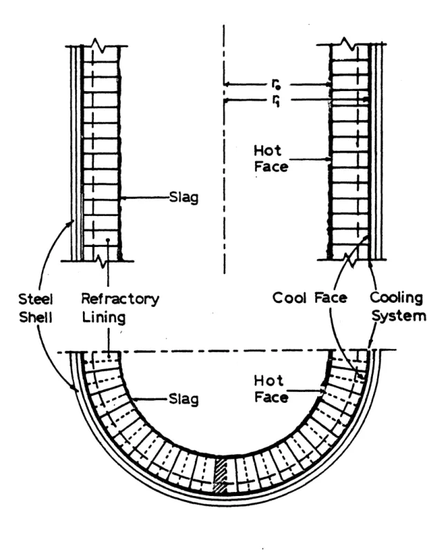
-slag tap to a quench tank from which it can be removed as a granular material. The molten slag is corrosive to the vessel shell. To maintain a high operating temperature and to protect the vessel shells from corrosion attack, refractory-brick lining systems (Fig. 1.2) are usually used. Such lining systems are generally in the form of composite cylinders primarily composed of layers of bricks in vertical (axial) and radial directions. The bricks are usually connected to adjacent bricks with jointing materials, such as mortars, for improving the system integrity and stability. Cooling systems are frequently adopted to fulfill certain requirements of temperature control during operation.
During the lifetime of a refractory-brick lining in a slagging gasifier, two general categories of failure may be observed [34]: (1) cracking, spalling, and joint failure due to thermal attack and (2) material degradation and mass loss due to corrosion attack by the slags
and gases.
The refractory lining is subjected to heat flux at the interior face (hot face) of the vessel and generally is cooled from the exterior face (Fig. 1.2). The adoption of a cooling system may reduce the
hot-face temperature, enabling a stable layer of slag to form on the inside hot face [36]. This layer may protect the refractory lining from exposure to the corrosive gases and molten slags. Moreover, the cooling system can reduce the shell temperature to a level that the corrosive agents on the shell are not active [30]. On the other hand, if the temperature differences across the lining thicknesses are large, a critical stress combination of tensile, compressive, and shear
- 34
-I
Hot
Face
I
Cc
L
Hot
,Slag
Figure 1.2 Schematic of Refractory Brick Lining System
1-Steel
Steel
Sh
Refractory
ng
1 w- 35
-stresses may arise in the lining. Such critical stress states may
cause cracking, and spalling problems in the bricks, and failures of the joints between the bricks. Furthermore, heat accumulation due to the reduction in thermal conductivity at locations across the cracks together with the possible degradation of the brick material due to hot slag penetration may accelerate the deterioration of the lining,
leading to eventual damage to the vessel shell.
In both acidic and basic coal slags, high-alumina and high-chromia dense refractories are usually used to reduce corrosion attack. Water
cooling at the exterior face of the lining also gives a beneficial effect. Substantial slag corrosion of the linings is still observed, however, due to its exposure to high-temperature gasification
environments during the life time of the system [303. The corrosion
process involves three mechanisms: dissolution, penetration, and
erosion. The chemical process of dissolution and penetration has been
extensively studied for certain candidate refractories for slagging
gasifiers [45,49,50,51,90]. Dissolution in a slag-refractory system is
the chemical reaction between the slag and the refractory, by which the refractory is gradually dissolved in the slag composite. The slag penetration can result in the changes of chemical and mechanical properties of the refractory. A common mechanical effect is the formation of numerous microcracks in the refractory and the resulting strength degradation. Erosion itself is not a problem for high-alumina and high-chromia bricks in slags. However, when it is accompanied by slag penetration and thermal stresses, it can result in significant spalling problems [65]. Such a spalling mechanism is not well
36
-understood. More studies toward a better understanding of this type of deterioration process are needed. W
An optimum design and operational control will reduce the
corrosion and thermal-attack problems in the lining system. In order to achieve a safe design and determine the optimum operational schemes, a thorough understanding of the behavior of lining systems in slagging gasification environments is required. Such a behavioral understanding will involve both thermomechanical material and system behavior, and corrosion behavior, as well as their interaction in the gasification environment. The present work is an attempt to accomplish these
objectives, with the aim to provide an analysis and design methodology for achieving reliable and durable lining systems. It is hoped that the results of this study will benefit the coal-gasification industry.
§1.3 REVIEW OF THE PREVIOUS MIT WORK
Over the past several years, comprehensive analytical and experimental studies have been undertaken at MIT dealing with the thermomechanical behavior of monolithic refractory concrete linings [19,20,70,88).
Constitutive models have been developed for both dense and insulating monolithic refractory concretes applicable to coal gasification vessel linings. In the development, experiments were performed on refractory concrete plate specimens subjected to biaxial compression at various temperatures. Based on the test results, a
- 37
-general hypoelastic model was developed for the thermomechanical
constitutive behavior of refractory concretes. The essential features of the model include a temperature dependent failure surface, elastic modulus and stress-strain curve. Within certain limitations the model
can be used to model behavior under cyclic thermal loadings. A temperature dependent creep model based on the concept of
thermo-rehologically simple material was also developed. The creep model incorporates a transient delayed elastic strain component and a
nonlinear irreversible flow component. These models were incorporated in a three dimensional thermo-mechanical finite element program for predicting the behavior of dual-component, monolithic refractory
concrete lined coal gasification vessels. A finite difference solution was used for the analysis of transient heat transfer analysis through
cracked, layered media, and incorporated in the three-dimensional nonlinear finite element computer program for the stress analysis.
The experience from this previous experimental and analytical work at MIT has been applied to the current research. However, special materials, systems, environmental conditions and related problems encountered in the current work required substantial new developments
in modeling and analytical/numerical procedures. New material models for the refractory bricks, structural models, a preliminary model for corrosion prediction, and analysis capability have been developed. With these new tools, the general behavior of a refractory lining
- 38
-§1.4 CURRENT RESEARCH OBJECTIVES AND APPROACH
The general objectives of the present study are (1) to develop predictive material models and an analysis capability to study the system behavior of refractory-brick linings in high-temperature, high-corrosion environments, and (2) through analytical/numerical simulations to reach specific guidelines for the design and operation of the lining systems.
The specific objectives of the study are:
(1) based on the available test data, to develop general
time-dependent, temperature-dependent material models. These models, when implemented in finite element program, will predict the thermomechanical behavior of linings in a transient heating process;
(2) to develop a general methodology and analysis capability (finite element program) for studying the reliability of lining systems in
gasification environments;
(3) through simulation and parameter studies, to assess the governing effects of different design factors and operational schemes on the
lining behavior;
(4) to develop an analytical model for studying the long-term corrosion behavior of the linings, and through simulation, to understand the corrosion behavior of the linings with
different lining materials, and in various operating conditions
in the slagging gasifiers;
(5) based on the analysis results, to provide specific guidelines for the design and operational control of the lining systems in
- 39
-In the determination of a proper configuration and operational scheme for a lining system, the designer usually faces many trade-offs before a final optimal solution is reached. Examples of these
trade-offs exist in materials selection (corrosion resistance, strength at elevated temperatures, and thermal conductivity); in operational procedures (levels of pressure, temperature, gas velocity, etc.); in the lining geometry (number of layers, thicknesses, etc.); in the heating scheme, and in the use of a cooling system. Such trade-offs can be assessed through accurate prediction of the overall lining performance in a gasification environment. The final optimal solution can be determined on an economic basis, comparing the total cost of
lining materials, labor, construction, replacement (material, labor, and down-time loss) due to possible damage in the lining systems, to projected benefits. Such an optimization process requires a broad
knowledge covering materials science, mechanical engineering,
structural engineering,
chemical
engineering, the manufacture of
refractories and gasifiers, and many other fields. Hence, an important
aspect of this work is the integration of results with results obtained
from other sources to provide a complete characterization of the lining
system.
The approach used to conduct this research may be summarized in the following steps:
(1) Collect and evaluate material data for hot refractory bricks and mortar. For different temperature levels the data
includes compressive strength, stress-strain curves, modulus of elasticity, strength under multiaxial loading conditions,
- 40
-creep curves, thermal conductivity, thermal expansion
behavior, and corrosion rate.
(2) Based on the available data and a general knowledge of
refractories, develop constitutive models for refractory
materials. Compare and verify predictions from the models
with experimental data.
(3) Study the long-term corrosion behavior of refractories in
slag. Develop analytical methods to predict residual lining
thickness and to evaluate long-term reliability of a lining
system.
(4) Study the effect of corrosion on the thermomechanical
properties of refractories. Modifications in
thermomechanical properties of refractories due to slag
corrosion will be included in
the thermomechanical analysis
of the lining systems.
(5) Develop a conductivity model for cracked media. Perform
transient heat transfer analyses and examine the local
effects of heat accumulation and stress concentration.
(6) Implement the developed material models into a finite element
program. Develop special elements for mortar and brick.
Simplify the structural model and define appropriate boundary
conditions.
(7) Perform thermomechanical analyses of linings using the
developed models. Predict stress-strain distributions within
the brick-mortar linings. Detect crack formation, spalling,
and joint failure by analysis.
- 41
-(8) Perform parameter studies to assess the effects of different
designs of the linings and different heating schedules on the thermomechanical behavior and reliability of the lining
systems. Optimize operational procedures and lining designs.
(9) Complete evaluation of analytical/numerical results. Make design and operational recommendations.
(10) Based on the analytical/numerical results, recommend future needs for experimental and analytical research.
§1.5 ORGANIZATION
A review of the lining systems and candidate materials used in a slagging gasifier is given in Chapter 2. The chapter includes the description of the gasification environment, the typical factors destructive to a refractory lining, the conceptual design of a lining system and the selection of candidate lining materials for slagging gasifiers. In Chapter 3 the material behavior, including
thermophysical and thermomechanical behavior, of the candidate materials is summarized. Associated temperature-dependent material models are proposed for implementation in the finite element program. These include the conductivity model, the time-independent constitutive model, and the creep model.
In Chapter 4, the slag corrosion behavior of refractory linings is studied. The typical corrosion mechanisms in a slag-refractory system are reviewed first. Analytical models for predicting residual lining
- 42
-thicknesses are proposed. Based on these models, the deterioration
behavior of the linings in
corrosive environment is
studied.
In
Chapter 5 the finite element formulations for the heat-transfer
analysis and for the stress analysis are summarized. The finite
element implementation of the interaction between heat transfer and
stress resultants is
presented. The modeling of the mortar-refractory
joint behavior is
included, and the implementations of the effects of
slag-penetration and spalling are also described. In
Chapter 6
extensive parameter studies are performed. Different combinations of
refractory materials, number of layers, layer thicknesses, and heating
schedules are studied. The results of these parameter studies
constitute the basis for the determination of an optimal design and
operational scheme.
Recommendations on conceptual design and operation of a refractory
lining system for slagging gasifiers are given in
Chapter 7. Finally,
in
Chapter 8 a summary of the study, conclusions, and future research
directions are presented.
CHAPTER
2
LINING SYSTEM AND
LINING MATERIALS
52.1 GASIFICATION ENVIRONMENT
The slagging gasifier is
conceptually a leading candidate for coal
gasification. It
offers several primary advantages over other types of
gasifiers. These include greater gas production capacity for a given
size unit, lower steam consumption, absence of tars, oils, and
condensable hydrocarbons in
the product steam, and relatively easy
removal of ash during operation. However, this highly efficient
conversion process is
generally accompanied by high operating
temperatures and pressures, complex gaseous composites, and molten
slag. This results in
an extraordinarily severe environment for the
structural components of the slagging gasification system.
Increasing temperature and pressure in
the gasifier can usually
increase operational efficiency and reduce the size of gasifier
[64].
The adopted temperatures and pressures in
a slagging gasifier generally
depend on the specific gasification process, the reactivity of the
coal, and the fluidity of the slag. The operating temperatures are
usually in
the range of 2500*F - 3300*F, and gas pressures are generally
in
the range from one atmosphere to 600 psi, but can be above 1000
-- 44
-psi. The high temperatures are not permissible for the vessel shell
of the gasifier, and thus the shell is generally protected by a
refractory lining system.
Gases typical to a slagging gasifier primarily consist of H20
(steam), H2, CO and CO2. Small amounts of CH4, N2, NH3, and H2S may
also exist. These processing gases can attack the refractory lining and vessel shell in various ways, and the level of damage by gas attack is generally temperature and pressure dependent. The steam can oxidize the iron-containing metal shell and cause cracking and spalling problems in the shells during heating cycles [2]. Such problems become very severe at high temperature levels. At elevated temperatures steam can affect refractory materials by causing the extraction of soluble oxides or hydroxides, resulting in the reduction of refractory strength and erosion resistance [40]. Hydrogen attack to the steel shell can be significant at temperature levels above 600oF, leading to loss in
material ductility and toughness [631. At high temperature levels
(>1700°F), hydrogen can remove silica and solid S102 from refractories and result in weight loss from the refractories [31]. CO disintegration of refractories, which causes the spalling of iron-containing materials and the corrosion of silicate refractories, is also an important factor in the lining design. In the consideration of the abovementioned gas attacks, the design of a gasifier usually adopts (1) a controlled low shell temperature (<650°F) with a protection layer (usually, made of chromium oxide) for the shell surface, and (2) dense, low
silica-containing refractory materials for the lining.
The high temperature in the slagging coal gasifiers melts the coal ashes into fluid slags. Slags run down the wall, flow over the bed of
45
-the gasifier, go through a slag tap to a quench tank and are removed as
a granular material. This scheme conceptually provides an easy method for waste disposal and creates minimal environmental problems. However,
the molten slag is corrosive to the vessel shell of the gasifier.
Hence, a lining system is designed not only as thermal barrier, but also as a protective system for the containment shell. Linings made of refractory bricks, with proper mortar joints and cooling systems, are usually adopted for these purposes.
The interaction between slag and the refractory is complex. It depends on the chemical compositions of the slag and the refractory, the slag temperature, and the slag viscosity. Usually the coal ash slags are very corrosive to most refractories. They are basically mixtures of various oxides, such as SiO 2, A0203, FeO, CaO, MgO, Fe203, MnO,
Na203, k20, Ti03, Ti02 and P205. In general, one can conveniently
categorize both the refractories and the slags into three classes,
acid, neutral, and basic, through the definition of a "Bases-to-Acids Ratio"(B/A Ratio):
Bases-to-Acids Ratio = (CaO + MgO + FeO + Fe203 + MnO + Na20 + K20)/(Si02 + A0203 + Ti0 3 + Ti0 2 + P205)
This ratio can be evaluated either on a molar or a weight basis. Ratios greater than 1 are considered basic, less than 1 acidic, and neutral if equal to 1. An acidic refractory will resist an acidic slag but will be attacked by (or dissolved in) a basic slag, and conversely. For each individual type of coal 'slag, theoretically, there is an optimum refractory with a minimum corrosion (dissolution) rate at certain temperatures. For corrosion resistance, high melting point and high
- 46
-softening temperature (refractoriness) are required in addition to high strength. It has been shown by extensive laboratory tests
[6,17,42,43,45,50,51,90) that those refractories consisting mainly of Cr203 , A-203 , and MgO are sufficiently resistant to attack by most US
coal slags.
The penetration of slags into refractories depends on the porosity and the temperature of the refractories. The penetrated slags cause differential volumetric change between the refractory matrix and the slag, which may introduce local cracking, crushing, and the degradation in strength of the slag-penetrated refractory. Combined with thermal loadings and slag errosion, slag penetration finally creates serious spalling problems and weight loss of the refractory [65). For this reason dense fusion cast refractory bricks are generally superior to
high-porosity refractories, such as porous sintered refractories.
A slag layer may form on the face of the refractory lining due to the adhesion of molten ash at temperatures lower than the critical value marking the transition between viscous and plastic behavior of
slag. Part of this layer will eventually flow down the lining surface under its own weight. The steady state thickness of this layer depends on the density and absolute viscosity of the slag, the amount of slag
flowing per unit width, the hydraulic gradient, and the slag
temperature [7,30,43]. This slag layer is desirable in the sense that it forms a protective layer for the refractories from hot slag
penetration, and gas corrosion [14). Such a protective layer can be obtained by reducing the slag temperature on the hot face of the refractory lining to a level below the critical temperature mentioned
![Figure 1.1 Coal Gasification Process [32]](https://thumb-eu.123doks.com/thumbv2/123doknet/14150784.471757/30.918.83.811.165.812/figure-coal-gasification-process.webp)
![Figure 2.2 Cracking and Spalling of Refractory Lining at Advanced Stage [16] C' wCW w C(D z -J TIME](https://thumb-eu.123doks.com/thumbv2/123doknet/14150784.471757/50.918.140.753.113.1092/figure-cracking-spalling-refractory-lining-advanced-stage-time.webp)
![Figure 2.12 Test Furnace for Rotating Corrosion Test in Molten Slag [90]](https://thumb-eu.123doks.com/thumbv2/123doknet/14150784.471757/63.918.127.786.88.993/figure-test-furnace-rotating-corrosion-test-molten-slag.webp)