HAL Id: hal-01903114
https://hal.archives-ouvertes.fr/hal-01903114
Submitted on 28 Jan 2019
HAL is a multi-disciplinary open access
archive for the deposit and dissemination of
sci-entific research documents, whether they are
pub-lished or not. The documents may come from
teaching and research institutions in France or
abroad, or from public or private research centers.
L’archive ouverte pluridisciplinaire HAL, est
destinée au dépôt et à la diffusion de documents
scientifiques de niveau recherche, publiés ou non,
émanant des établissements d’enseignement et de
recherche français ou étrangers, des laboratoires
publics ou privés.
A Bi-Stable von-Mises Truss for Morphing Applications
Actuated Using Shape Memory Alloys
Silvestro Barbarino, Farhan Gandhi, Rodolphe Visdeloup
To cite this version:
Silvestro Barbarino, Farhan Gandhi, Rodolphe Visdeloup. A Bi-Stable von-Mises Truss for
Mor-phing Applications Actuated Using Shape Memory Alloys.
ASME 2013 Conference on Smart
Materials, Adaptive Structures and Intelligent Systems, Sep 2013, Snowbird, United States.
�10.1115/SMASIS2013-3062�. �hal-01903114�
A BI-STABLE VON-MISES TRUSS FOR MORPHING APPLICATIONS ACTUATED
USING SHAPE MEMORY ALLOYS
Silvestro Barbarino Farhan S. Gandhi Rodolphe Visdeloup
Mechanical, Aerospace and Nuclear Engineering Department,
Rensselaer Polytechnic Institute, Troy, NY 12180, USA Supmeca - Superior Engineering Institute of Paris, Toulon, France
ABSTRACT
The present study focuses on a bi-stable von-Mises truss (VMT), with integrated Shape Memory Alloy (SMA) wires which are resistively heated to provide the actuation force to transition the VMT from one stable equilibrium condition to the other, and back. This coupled VMT-SMA system can potentially be used in structural morphing applications. The paper considers in detail the design of the system, equilibrium between the VMT and the SMA wires, the initial pre-stress required in the two SMA wires, explains how the active (heated) SMA wire drives the VMT beyond the unstable equilibrium state, and the VMT in moving to the second stable equilibrium state pre-stresses the passive (unheated) SMA wire. The two SMA wires switch roles in moving the VMT back from the second to the first stable equilibrium state. A prototype is designed and fabricated and the transition of the VMT from one equilibrium state to the other, and back, is experimentally demonstrated. The governing differential equation representing the VMT behavior is coupled with equations representing the SMA behavior based on the Brinson thermo-mechanical model. The numerical predictions of system displacements versus temperature and time show good correlation with experimental results.
INTRODUCTION
Bi-stable or multi-stable structures, which can undergo large deformation as they transition between two or more stable equilibrium positions, are of significant interest in morphing applications. A very attractive feature of such structures is that the equilibrium positions require neither any power nor any locking mechanisms to hold. A morphing structure based on a bi-stable system can be designed to have its initial and final configurations corresponding to the first and second equilibrium stable positions. Transitioning between these two
stable states, the system passes thru an unstable equilibrium point and undergoes a phenomenon known as snap-through.
Bi-stable and multi-stable systems are of particular interest for morphing applications. Hyer [1] and Cerami and Weaver [2] have investigated using unsymmetric composite laminates to create multi-stable shapes for morphing. The same concept was then adopted by Daynes et al. [3] to create a multi-stable air inlet, and by Diaconu et al. [4] to create a bi-stable plate used to extend the chord of an airfoil. In a similar application of bi-stable unsymmetric composite laminates, Schultz [5] developed a bi-stable airfoil-like device for wing twist morphing. Schultz also found that his device could be bi-stable without the help of unsymmetric laminates, and created a steel version of the same device.
Bi-stable elastic arches have also been considered for helicopter rotor blade morphing in a recent study by Johnson et al. [6,7]. Johnson envisioned that a single bi-stable elastic arch could be used to effectively extend the chord of a rotor blade. Figure 1 shows a schematic of the concept. That study used an arch clamped at both ends, and focused on the design of flexures to avoid high strains, leading to failure, when the arch transitioned from one stable equilibrium condition to the other. Another solution to limit high local strains was presented by Pontecorvo et al. [8], which envisioned a novel cosine profile for the arch to reduce peak stresses. One example of application of their concept for rotor blade chord morphing is shown in Figure 2.
In the present study, a bi-stable system known as a von-Mises truss (VMT) is adopted as replacement for the elastic arch to avoid the build-up of high strains leading to failure. Introduced by von-Mises [9] in 1923, a VMT is dynamically equivalent to a one-term Galerkin expansion of a continuous arch [10]. The VMT has been integrated with Shape Memory Alloys (SMAs) [11] to be used as actuators, exploiting the Shape Memory/Constrained Recovery effect [12]. Shape Memory Alloys have demonstrated their suitability for many
quasi-static applications [13] due to their high structural integration potential and energy density. By coupling the bi-stable von-Mises truss with Shape Memory Alloy actuators to command the snap through, a morphing structural assembly is created with the potential to be incorporated into more complex structures.
Figure 1. Schematics of bi-stable arch used for chord extension by Johnson et al. [7].
Figure 2. Isometric CAD view of a cellular structure with bi-stable arches (red) used for helicopter rotor blade chord
morphing.
This paper focuses on two-way actuation (snap-through and snap-back) of the von-Mises truss. The proposed configuration uses two Shape Memory Alloy wires positioned to take advantage of the symmetric behavior of the von-Mises truss with respect to the unstable equilibrium. These wires are pre-strained by the von-Mises truss in either equilibrium state to achieve cyclic working.
Both numerical and experimental investigations are carried out. A semi-analytical model is developed in Matlab based on the numerical integration of the VMT governing equations capable of predicting the static and dynamic behavior of the VMT. This was then coupled with the Brinson thermo-mechanical model for the Shape Memory Alloys [12], to estimate the activation temperature and stress levels within the alloy required for actuation of the von-Mises truss. A prototype was built and tested. Experiments showed the cyclic, two-way actuation of the device and provided good correlation with the analysis.
CONCEPT
Von-Mises truss
A von-Mises truss bi-stable system is shown in Figure 3.
The two planar, pin-jointed truss elements of length 𝑉 are
assumed to be rigid. All mass can be concentrated at the vertex of the truss to simplify the analysis. The truss elements are connected at the vertex, which can slide vertically in the direction, and their free ends are allowed to slide in the
horizontal direction . A spring 𝑉 inter-connects the free ends
and provides stiffness for the truss. The initial angle of the truss
elements is denoted by 𝜃0, positive counterclockwise, with the
displacement defined positive clockwise and denoted θ. Murray and Gandhi [14] derived the equation of motion by writing the kinetic and elastic potential energies of the system and using them in Lagrange’s equation. The model was also statically and dynamically validated using ANSYS Finite Element analysis.
Figure 3. Diagram of a von-Mises truss system. The static equation for such system is reported in Eq.1: { 𝑉[ 𝑖 𝜃0 − 𝑉] [ 𝑉√ − 𝑖 𝜃0 − 𝑉 − 𝑉𝑐 𝜃0]}
√ − 𝑖 𝜃0 − 𝑉
= 𝐹 (1)
The typical static behavior of a von-Mises truss is shown in Figure 4. The full displacement (stroke) of the VMT is defined
by its geometry ( 𝑉 𝑖 𝜃0), that is the amount of
displacement corresponding to vertex travel from the first stable equilibrium position to the second one. The structure exhibits an initial positive stiffness up to a critical load (called
𝐹𝑁𝐴𝑃). Thereafter, a region with negative stiffness is
encountered, in which snap-through can occur. To have bi-stability, the force has to cross the zero level for a non-zero displacement, which always occurs for the von-Mises truss due to its symmetric behavior. In the last portion, the structure again exhibits positive stiffness. The slope of the initial portion of the curve (up to the critical force to induce snap-through) is representative of the stiffness of the VMT system. The initial stiffness of the VMT is useful to carry a static load with relatively small displacements. If a stiffer structure is needed, some parameters of the von-Mises truss such as the spring
stiffness 𝑉 or the initial angle 𝜃0 (or a combination of both)
can be increased.
Figure 5 illustrates the force versus vertex displacement behavior of a “bi-stable” von-Mises truss under the conditions of displacement control (solid line) and force control (dashed
line). Under displacement input, it is possible to reproduce the negative stiffness behavior but not the snap-through, as the vertex position is hold during loading. On the other hand, under force input, it is possible to reproduce the snap-through but not the negative stiffness. Snap-through occurs in force control as
soon as 𝐹𝑁𝐴𝑃 is exceeded and only if the vertex of the VMT is
not held. Snap-through will be used in this study to induce large displacements with relatively small force and displacements in the Shape Memory Alloys wires.
Figure 4. Static behavior of a VMT: markers individuate the
force 𝐹𝑁𝐴𝑃 required to snap-through and the two stable
equilibrium positions.
Figure 5. Displacement vs. force input on a bi-stable VMT system.
Shape Memory Alloys
Shape Memory Alloys, first discovered in 1932, are metal alloys (commonly nickel-titanium) that exhibit both the unique characteristics of large recoverable strains and large induced
internal forces when exploiting the Shape Memory/Constrained Recovery effect [15].
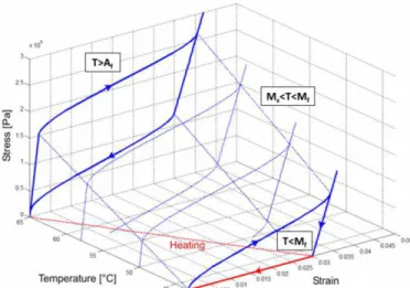
Figure 6. Typical stress-strain-temperature behavior of Shape Memory Alloys.
Aforementioned thermo-mechanical properties of SMAs are due to a crystallographic phase transformation from a body-centered cubic structure (austenite/parent phase, present at high
temperatures) to a face-centered cubic structure
(martensite/product phase, present at low temperatures), or vice versa. If the austenite temperature is lower than the environmental temperature, the so-called Super-elastic effect is exhibited upon changes in the internal stress state. Otherwise, the high residual strain may be recovered by a temperature change and the Shape Memory effect takes place (Figure 6).
SMAs are ideal for their favorable actuation performance-per-weight ratio, but are limited to low actuation frequencies (quasi-static) due to the thermal inertia. One of the major current drawbacks in engineering applications is the difficulty of fully characterizing their behavior, which is highly non-linear and load history dependent. In this study, the phenomenological model developed by Brinson et al. [12] is used. The basic assumption, inherited from Tanaka [16] and Liang & Rogers’ [17] models, is that the thermo-mechanical process is fully described by three state variables: strain 𝜀, temperature 𝑇 and martensite volume fraction 𝜉. The martensite volume fraction is intended as a measure of the phase transformation and differentiated into stress induced 𝜉 and temperature induced 𝜉 , with 𝜉 = 𝜉 + 𝜉 and < 𝜉 < . Relations for the two terms are derived by the phase kinetics. The constitutive relation for Brinson model is expressed in Eq.2
𝜎 − 𝜎0 = 𝜉 𝜀 − 𝜀0 + 𝛩 𝑇 − 𝑇0 + 𝛺 𝜉 𝜉 − 𝜉0 (2)
where the subscript 0 represents the initial condition, 𝜎 is the stress, is the modulus of elasticity, 𝛩 is the thermal expansion coefficient and 𝛺 is the transformation tensor. This equation shows that the stress consists of three parts (in the order): mechanical, thermal and induced by phase transformation.
Table 1. Selected SMA material properties.
Martensite Young modulus, EM [GPa] 17 Austenite Young modulus, EA [GPa] 50 Martensite start temperature, MS (°C) 50 Martensite finish temperature, MF (°C) 45 Austenite start temperature, AS (°C) 60 Austenite finish temperature, AF (°C) 70 Critical stress de-twinned martensite start [MPa] 75 Critical stress de-twinned martensite finish [MPa] 260 Thermal expansion coefficient 𝛩 [MPa/°C] 0.55 Variation of austenite critical temperatures 𝐴 with stress [MPa/°C] 12 Variation of martensite critical temperatures with stress [MPa/°C] 12 Limit strain 𝜀 [%] 5.7 Ultimate elongation [%] 8
In this study, SmartFlex05 Ni-Ti wires with 480 𝜇 diameter were provided by SAES Getters and used. The thermo-mechanical properties of the SMA necessary for the Brinson model are reported in Table 1. Some were provided by the manufacturer while others were measured experimentally performing mechanical tests in an Instron 4444 testing machine. Correlation between the Matlab implementation of the Brinson model and the characterization experiments was verified (not reported).
Combined VMT and SMA system
The coupling of the bi-stable von-Mises truss with Shape Memory Alloys as actuators has the potential to create a morphing structural assembly capable of undergoing large displacements with commanded changes in state and not requiring any locking mechanism. This could then be integrated into more complex structures.
Two-way actuation (snap-through and snap-back) was deemed of primary importance for such morphing mechanism. To achieve this goal, the ideal configuration would use heating of a set of pre-strained SMA wires (one or multiple) to actuate the VMT and induce snap-through in one direction. During the transition of the VMT from the first stable position to the other, the heated (martensite to austenite phase transformation) SMA
wires can recover their initial pre-strain 𝜀𝑖 𝑖𝑡. This is possible
because the SMA wires only need to apply sufficient force to
reach the peak 𝐹𝑁𝐴𝑃 to initiate snap-through in the VMT. At
this point no further action is required from the SMAs, which can be cooled down (austenite to martensite phase transformation). In the meanwhile, the VMT will cross the zero-force level for a non-zero displacement (corresponding to the unstable equilibrium position), and move towards the second stable equilibrium. While approaching this second position, the same SMA wires (or a different set) can be pre-strained again by the von-Mises truss due to its positive stiffness around the stable positions. If the SMA wires are positioned to take advantage of the symmetric behavior of the von-Mises truss with respect to the unstable equilibrium, the process can be inverted and snap-back induced.
This type of solution allows for cyclic, two-way actuation. However, it implies that the SMA wires must be initially attached to the VMT with the desired initial pre-strain. In addition, the VMT must be designed to be able to induce the desired amount of pre-strain in the SMAs. In this study, the VMT is designed to be able to pre-strain the SMAs in
correspondence of its peak force 𝐹𝑁𝐴𝑃. This is because after
the first cycle the VMT will be able to apply a maximum pre-strain in the SMA wires in correspondence of its peak force. The two stable positions of the overall assembly will differ from the ones of the VMT alone, must be determined, and will
be in the surroundings of 𝐹𝑁𝐴𝑃.
For practical purposes, another critical feature of the selected design would include relatively short SMA wires capable of amplifying their recoverable strain to induce much larger displacements in the von-Mises truss. A value of recoverable strain of 3% in length for the SMAs is chosen in this study as a compromise between actuation performance, stability with cycles and fatigue life [18].
Several configurations were considered and then discarded because didn’t meet the aforementioned requirements. Initially a configuration with two SMA wires aligned with the vertical motion of the vertex of the VMT, each pulling in one direction, was considered. The length required for this case was several times larger than the length of the links of the VMT and
suitable only for very small values of the initial angle 𝜃0, and
therefore was discarded. Another configuration considered SMA wires attached to the vertex and positioned to replicate the geometry of the links of the VMT. In this case, the SMA wires would completely recover their pre-strain upon reaching the horizontal position of the VMT. However, this position corresponds to an unstable equilibrium with zero force to hold, and therefore a source of bifurcation.
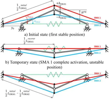
a) Initial state (first stable position)
b) Temporary state (SMA 1 complete activation, unstable position)
c) Final state (second stable position)
The final proposed solution is shown in Figure 7. It uses two Shape Memory Alloy wires positioned to take advantage of the symmetric behavior of the von-Mises truss with respect to the unstable equilibrium while minimizing their overall length. The SMA wires are constrained at both ends separately from the VMT, whose ends can instead slide horizontally. Connection to the vertex of the VMT is accomplished by means of a positive and negative offset, respectively (Figure 7a). This offset is the key feature allowing for two-way actuation. The SMA wires are heated independently (and not simultaneously) to induce snap-through motion in either direction. When the first (red) SMA wire is heated, the second (blue) stays at its low-temperature state (martensite) and behaves as a passive SMA to be pre-strained. Motion from the first to the second stable position is induced. As the first SMA wire approaches its complete strain recovery, the unstable equilibrium position of the VMT is crossed and the configuration shown in Figure 7b is reached. The presence of the offset allows moving the VMT beyond the unstable position, therefore guiding its motion towards the second stable position in a transient where the first SMA wire has no additional actuation authority. At this point heating of the first SMA is terminated. Both SMA wires are
now “passive” and the spring 𝑉 allows the VMT to reach the
second stable position (Figure 7c). The process can then be inverted (heating of the second blue SMA wire only) for the snap-back motion.
The stiffness of the VMT must be tailored to the adopted SMA wires. For the two-way actuation to be possible, the VMT must be able to pre-strain both wires to the desired level by applying the required force along the longitudinal direction of each wire. It should be noted that the initial (Figure 7a) and final (Figure 7c) case must be symmetric, with the first and second SMA wires swapping their pre-strain levels in these two configurations. In each state the two wires have different pre-strain levels due to the geometry of the system. This is beneficial to the working of the assembly, as the active SMA possesses larger pre-strain (and actuation authority) than the passive one (which must be passively deformed).
Analysis of the geometry of the combined system allows deriving some useful relationships among the several parameters. Only the snap-through motion is described, as the snap-back is similar and requires inverting the first and second SMA wires as the passive and active one, respectively. One assumption made in the following is that the active SMA wire is expected to be able to fully recover its pre-strain (set to
𝜀𝑖 𝑖𝑡= % in length) thus reaching the horizontal position and
length 𝑟𝑒𝑐 𝑣𝑒𝑟 𝐴 , as shown in Figure 7b and reported in Eq.3:
𝐴
𝑖 𝑖𝑡𝑖 = + 𝜀𝑖 𝑖𝑡 𝐴
𝑟𝑒𝑐 𝑣𝑒𝑟
.
(3)This is due to the VMT exhibiting zero stiffness when approaching the unstable position, which also corresponds to the state of complete actuation for the heated SMA. It should
also be noted that 𝑟𝑒𝑐 𝑣𝑒𝑟 𝐴 is the same for both SMA wires once
the completely horizontal position is reached.
The geometry of the VMT ( 𝑉, 𝜃0) is defined first in the
design process of the combined system. This would be set according to the requirements of the morphing structure to be
actuated. Note that 𝑉 is not defined at this point. As previously
mentioned, the choice of the common working point between the von-Mises truss and the two SMA wires is crucial to the two-way cycling. The VMT must be able to pre-strain cycle after cycle both SMA wires. Therefore, the initial pre-strain in the wires (and associated stress levels) must be compatible with the force and displacement of the vertex of the von-Mises truss. In this study, a clear working point has been identified in the
peak force 𝐹𝑁𝐴𝑃 of the VMT. This is representative of the
maximum force that the VMT can exert on the SMA wires and must be sufficient to pre-strain both. Since the static equation of the VMT is known (Eq.1), the displacement at which this condition of maximum force occurs can be analytically determined (Eq.4)
= 𝑉 𝑖 𝜃0 − √[ − 𝑐 𝜃0 ] . (4)
Other quantities in the new equilibrium position are:
𝐻𝑒 = 𝑉 𝑖 𝜃0 − 𝜃0𝑒 = 𝑖 𝐻𝑒 𝑉 0= 𝐴 𝑟𝑒𝑐 𝑣𝑒𝑟− 𝑉𝑐 (𝜃 0𝑒 ) (5)
with 𝐻𝑒 the new vertical position of the vertex and
0 the
distance between the free end of each link of the VMT and the grounding of the SMA wires.
Having defined the new initial equilibrium position for the
VMT, and having set the amount of offset (ℎ 𝐴 and ℎ 𝐴 )
for the two wires, the initial angles and lengths of both SMA wires can be found as
𝜃𝑖 𝑖𝑡𝑖 𝐴 = 𝑐 ( + 𝜀𝑖 𝑖𝑡) 𝜃𝑖 𝑖𝑡𝑖 𝐴 = 𝑎 𝐻 𝑒 − ℎ 𝐴 𝐴 𝑟𝑒𝑐 𝑣𝑒𝑟 𝐴 𝑖 𝑖𝑡𝑖 =𝐻𝑒 + ℎ 𝐴 𝑖 (𝜃𝑖 𝑖𝑡𝑖 𝐴 ) 𝐴 𝑖 𝑖𝑡𝑖 =𝐻𝑒 − ℎ 𝐴 𝑖 (𝜃𝑖 𝑖𝑡𝑖 𝐴 ) (6)
Other useful relationships include how the angles at which both SMA wires are mounted and their length changes with the vertical displacement of the vertex of the von-Mises truss (Eq.7).
𝜃 𝐴 = 𝑖 [
𝑉 𝑖 𝜃0 + ℎ 𝐴 − ]
𝜃 𝐴 = 𝑖 [ 𝑉 𝑖 𝜃0 − ℎ 𝐴 − ] √[ 𝑉 𝑖 𝜃0 − ℎ 𝐴 − ] + 𝑟𝑒𝑐 𝑣𝑒𝑟 𝐴 𝜀 𝐴 = √[ 𝑉 𝑖 𝜃0 + ℎ 𝐴 − ] + 𝐴 𝑟𝑒𝑐 𝑣𝑒𝑟 𝐴 𝑟𝑒𝑐 𝑣𝑒𝑟 − 𝜀 𝐴 = √[ 𝑉 𝑖 𝜃0 − ℎ 𝐴 − ] + 𝐴 𝑟𝑒𝑐 𝑣𝑒𝑟 𝐴 𝑟𝑒𝑐 𝑣𝑒𝑟 −
Therefore, the initial pre-strain values of both SMA wires
are known (calculated for = ) and the correspondent
necessary pre-stress levels (𝜎 𝐴 and 𝜎 𝐴 ) can be
determined after characterizing the SMA material (or running the Brinson model with the set of parameters shown in Table 1). The stress in both SMA wires can then be converted into force along the vertical motion of the vertex of the VMT according to Eq.8
𝐹 𝐴= 𝐹 𝐴 + 𝐹 𝐴
= 𝜎 𝐴 𝐴 𝐴 𝑖 𝜃 𝐴 + 𝜎 𝐴 𝐴 𝐴 𝑖 𝜃 𝐴
(8)
where 𝐴 𝐴 and 𝐴 𝐴 are the cross sections of each SMA
wire.
Finally, the value of spring stiffness 𝑉 necessary to
combine the VMT and the SMA wires so to achieve 𝐹𝑁𝐴𝑃=
𝐹 𝐴 can be determined from the static equation Eq.1 as
𝑉= −𝐹 𝐴√𝑐 𝜃0
𝑉⌊𝑐 𝜃0 − √𝑐 𝜃0 ⌋√ − 𝑐 𝜃0 (9)
ANALYSIS
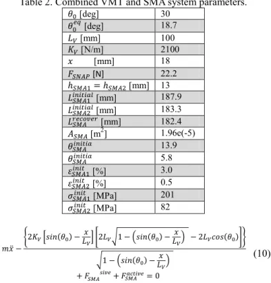
The static and dynamic behavior of the combined system comprising of a von-Mises truss and two SMA wires, and capable of two-way actuation, is investigated in this section. The geometry of the VMT system was defined first and the other quantities derived according to the design process exposed in the previous section. Table 2 summarizes the main parameters of the designed combined system.
Numerical analysis of the combined system has been carried out using MathWorks MATLAB R2012a. A dynamic equation of motion (Eq.10) has been derived starting from Lagrange’s equation. The entire mass is concentrated at the vertex. The action of the two SMA wires on the VMT system is accounted for in terms of external forces along the vertical motion of the vertex of the von-Mises truss. In particular, the active SMA wire applies a force in the direction of the snap-through motion while the passive one applies a resistive force (acts like a spring). The dynamic equation is numerically integrated using the ordinary differential equation solver ode23tb, based on an explicit Runge-Kutta formula [19]. The solution is obtained incrementally and at each step a function
implementing the Brinson’s model is used to calculate the evolution in martensite volume fraction, strain and stress (due to increase in temperature) in the SMA wires.
Table 2. Combined VMT and SMA system parameters.
𝜃0 [deg] 30 𝜃0𝑒 [deg] 18.7 𝑉 [mm] 100 𝑉 [N/m] 2100 [mm] 18 𝐹𝑁𝐴𝑃 [N] 22.2 ℎ 𝐴 = ℎ 𝐴 [mm] 13 𝐴 𝑖 𝑖𝑡𝑖 [mm] 187.9 𝐴 𝑖 𝑖𝑡𝑖 [mm] 183.3 𝐴 𝑟𝑒𝑐 𝑣𝑒𝑟 [mm] 182.4 𝐴 𝐴 [m2] 1.96e(-5) 𝜃𝑖 𝑖𝑡𝑖 𝐴 13.9 𝜃𝑖 𝑖𝑡𝑖 𝐴 5.8 𝜀𝑖 𝑖𝑡 𝐴 [%] 3.0 𝜀𝑖 𝑖𝑡 𝐴 [%] 0.5 𝜎𝑖 𝑖𝑡 𝐴 [MPa] 201 𝜎𝑖 𝑖𝑡 𝐴 [MPa] 82 ̈ − { 𝑉[ 𝑖 𝜃0 − 𝑉] [ 𝑉√ − 𝑖 𝜃0 − 𝑉 − 𝑉𝑐 𝜃0]} √ − 𝑖 𝜃0 − 𝑉 + 𝐹 𝐴 𝑖𝑣𝑒+ 𝐹 𝑐𝑡𝑖𝑣𝑒 𝐴 = (10)
To distinguish between the snap-through and the snap-back motion, a boolean variable is introduced in the simulation to switch the SMA wire being heated while keeping the other passive (at low, martensitic temperature). Results for the snap-through motion only (one way) are presented in this section, as the snap-back motion is perfectly symmetrical. A single cycle of heating-cooling for the active SMA wire is presented.
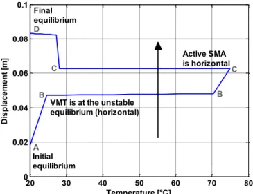
Figure 8 shows the vertical displacement of the vertex of the VMT as a function of the activation temperature of the active SMA wire (the other wire is kept at a constant temperature of 20°C). The simulation finds the initial equilibrium position of the combined system to be at 18.3 mm (point A) displacement, close to the 0.018 m originally
estimated in the design process ( in Table 2). As
temperature in the active SMA wire is increased, the VMT snaps-through up to 48 mm (point B). This corresponds to the VMT being almost horizontal and close to its unstable position. In this position both passive and active SMA wires have roughly the same amount of strain and the active SMA has to start pre-straining the passive one. As temperature keeps increasing, the active SMA reaches its horizontal position ( = 63 mm, point C) and has fully recovered its pre-strain, therefore it is not able to apply any additional force. Further increase in temperature does not produce any additional force or motion. Reducing the temperature, on the other hand, allows reaching the second equilibrium position for the combined system ( = 83.4 mm, point D).
The presence of sudden jumps in the displacement of the vertex of the VMT is due to the crossing of the negative stiffness region of the VMT (Figure 9) and the SMA wires alternatively going slack or suddenly undergoing tension. These discontinuities cannot be eliminated and are part of the behavior of the designed system.
Figure 8. VMT vertex displacement vs. activation temperature of active SMA wire.
Figure 9. VMT vertex displacement vs. activation temperature of active SMA wire.
Figure 10 shows the evolution of the strain within the SMA wires as a function of the displacement of the vertex of the VMT. The simulation estimates initial pre-strain values for both wires slightly larger than the predictions from the design
process (𝜀𝑖 𝑖𝑡𝑖 𝐴 = 0.032 and 𝜀𝑖 𝑖𝑡𝑖 𝐴 = 0.006). The active SMA
wire (solid red curve) recovers its pre-strain completely corresponding to 63 mm (point C) vertex vertical displacement, at which point the wire is perfectly horizontal. When the horizontal position is overcome, its strain increases again up to
the initial pre-strain value for the passive SMA wire. On the other hand, the passive SMA wire (dashed blue curve) follows a different evolution. As the VMT moves, it becomes loose and its pre-strain does not change. After snap-through occurs, the VMT deforms the passive wire up to the pre-strain level necessary for the snap-back motion.
Figure 10. Strain in the SMA wires vs. VMT vertex displacement.
Figure 11. Stress in the SMA wires vs. VMT vertex displacement.
The presence of slack in the SMA wires can be appreciated in Figure 11. Initial stress values in both SMA wires are very close to the ones estimated in the design phase. The passive SMA wire has a straightforward behavior. As soon as the snap-through motion begins, the passive wire becomes loose and its stress level drops. After the horizontal position is crossed and the slack is removed, the stress increases. The active SMA, on the other hand, reduces its stress level from the initial value due to the snap-through behavior of the VMT, which enters the
20 30 40 50 60 70 80 0 0.02 0.04 0.06 0.08 0.1 Temperature [°C] D is pl ac em en t [ m ] VMT is at the unstable equilibrium (horizontal) Initial equilibrium A Final equilibrium D Active SMA is horizontalC C B B 0 0.02 0.04 0.06 0.08 0.1 -40 -30 -20 -10 0 10 20 30 40 Displacement [m] Fo rc e [N ] Final Initial A D B C 0.010 0.02 0.03 0.04 0.05 0.06 0.07 0.08 0.09 0.005 0.01 0.015 0.02 0.025 0.03 0.035 Displacement [m] St ra in , active SMA passive SMA Initial Final A A D D C C B 0.01 0.02 0.03 0.04 0.05 0.06 0.07 0.08 0.09 0 50 100 150 200 Displacement [m] St re ss [M Pa ] active SMA passive SMA Final Initial A A D D B B C
negative stiffness region and exhibits a reducing resisting force. This terminates around = 48 mm (point B), when the VMT has reached its unstable position but the active SMA must overcome the resistance of the passive wire and start stretching it. At = 63 mm (point C) the active SMA wire is completely horizontal and cannot influence the motion of the VMT any further. Its internal stress levels are close to null as only the passive SMA wire is offering some resistance. From this point and up to = 83.4 mm (point D), the VMT alone is able to stretch both SMA wires, increasing their internal stress level. It should be noted that the final values of internal stress of both SMA wires are similar (and inverted) to their initial stress levels. The stress levels within the active and passive SMA wires can also be converted into the vertical active and resistive force, respectively, acting on the vertex of the von-Mises truss (Figure 12).
Figure 12. Vertical force in the SMA wires vs. VMT vertex displacement.
As a final note for this section, the Brinson phenomenological model presents some shortcomings when temperature and stress of the SMA wire change simultaneously, as discussed by Elahinia [20]. In the proposed configuration, this occurs when the VMT system transitions between the positive and negative stiffness regions. During heating, the SMA wire actuates the VMT by applying an increasing vertical
force to the vertex of the VMT up to 𝐹𝑁𝐴𝑃. As soon as
snap-through is induced, the VMT tends to reach the second stable equilibrium and the SMA wire becomes slack, therefore experiencing a drop in internal stress. At the same time, cooling of the SMA begins. The Brinson model is not able to correctly estimate what happens during this phase (between points A and B). However, due to the very fast occurrence of snap-through combined with the SMA wires going alternatively slack during this motion, and the interest in this preliminary study in
achieving and demonstrating two-way actuation, this shortcoming has been neglected.
EXPERIMENTS Prototype
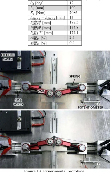
An experimental prototype for the proposed combined VMT and SMA system was built to validate the numerical simulations. The use of commercial off-the-shelf components for ease of use affected the design of the final prototype (Figure 13) and its main parameters are summarized in Table 3.
Table 3. Main parameters of the experimental prototype.
𝜃0 [deg] 12 𝑉 [mm] 100 𝑉 [N/m] 2086 ℎ 𝐴 = ℎ 𝐴 [mm] 13 𝐴 𝑖 𝑖𝑡𝑖 [mm] 178.5 𝐴 𝑖 𝑖𝑡𝑖 [mm] 174.8 𝐴 𝑟𝑒𝑐 𝑣𝑒𝑟 [mm] 174.1 𝜀𝑖 𝑖𝑡 𝐴 [%] 2.5 𝜀𝑖 𝑖𝑡 𝐴 [%] 0.4
Figure 13. Experimental prototype.
The rigid links of the VMT have built-in pin-joints at both ends. One end of each link can move horizontally on sliders. The other converges in the vertex of the VMT. As opposed to the model, the links don’t merge in a single pin-joint but are positioned as close as possible, thus allowing keeping both links in the same plane. The vertex of the VMT is therefore 0.02 0.03 0.04 0.05 0.06 0.07 0.08 -25 -20 -15 -10 -5 0 5 10 15 20 25 Displacement [m] SM A V er tic al F or ce [N ] Factive SMA Fpassive SMA Final Initial A A D D B C C
constituted of a plate which can slide vertically on a rail, connects to the rigid links of the VMT and hosts also the supports for the SMA wires. These supports are bolts with holes that allow the wire to pass-through. Electrical insulation is used when connecting the SMA wires to the rest of the prototype as the heating is achieved by means of Joule effect. Convective cooling is then used to induce the opposite phase transformation. The SMA wires are connected to fixed boundaries at the extreme ends. The stiffness of the VMT is due to a tension spring located underneath the rigid links and connected to their sliding ends by means of a spacer.
Two separate electric circuits are connected to each SMA wire and commanded by an external switch. A Tektronix PWS4000 DC power supply is used as source of electrical current to heat the SMA wires alternatively. The power output and the reading from a K-type thermocouple are sent to a NI DAQ 6212 acquisition system commanded by LabView software. Also, measurements from a linear potentiometer attached to the sliding base of one of the VMT links records the horizontal displacement . This motion is then related to the vertical displacement of the vertex of the VMT using Eq.11
= 𝑉 𝑖 𝜃0 − 𝑉 𝑖 [𝑐 𝑐 𝜃0 + ]
.
(11)A 1.3 A electrical current was used during the experiments. This value was chosen as a trade-off between (1) the achievement of the complete activation temperature and (2) actuation time, and (3) the time needed by the thermocouple to read increments in temperature (due to thermal inertia).
Tests and correlations
Experiments showed the occurrence of commanded snap-through and snap-back motion by alternating the Joule heating of the two SMA wires. Two sets of data will be presented in this paper. The first shows the experimental occurrence of the two-way actuation.
Figure 14. Commanded activation of the SMA wires for two-way actuation.
Figure 15. Two-way actuation: potentiometer.
Figure 16. Two-way actuation: VMT vertex displacement.
Figure 17. Two-way actuation: VMT vertex motion vs. temperature. 0 20 40 60 80 100 -0.1 0 0.1 0.2 0.3 0.4 Time [s] H or izo nt al D is pl ac em en t [ m m ] Experimental Snap-through Snap-back 0 20 40 60 80 100 -0.005 0 0.005 0.01 0.015 0.02 0.025 0.03 0.035 0.04 Time [s] D is pl ac em en t [ m ] Experimental Final Initial Initial 20 25 30 35 40 45 50 -0.01 0 0.01 0.02 0.03 0.04 0.05 Temperature [°C] D is pl ac em en t [ m ] Experimental
SMA wire 1 heating SMA wire 1 cooling
Figure 14 illustrates the commanded activation of the SMA wires, and Figure 15 and 16 the measured horizontal and vertical displacement of the VMT as a function of time, respectively. From these figures it is possible to infer that the experimental snap-back motion is faster than the snap-through one. During the forward motion, the prototype takes roughly 25 seconds (roughly between 15 and 40 seconds in Figure 15) to reach the unstable equilibrium and then snaps-through. It was established that minor fabrication asymmetries led to the prototype not exhibiting a completely symmetrical behavior in the two directions of motion. Figure 17 shows the displacement of the vertex of the VMT as a function of the temperature of the active SMA wire. Note that when the first SMA wire starts cooling, the other SMA wire is heated to induce snap-back.
Figure 18. Temperature profile for the active SMA.
Figure 19. One-way actuation: displacement vs. time. The second set of data focuses on the one way actuation, which is correlated with the numerical simulation. Figure 18 illustrates the experimental temperature profile for the active SMA wire, as measured by the thermo-couple, and the one
modeled in the simulation. Figure 19 and 20 show a good correlation between the model and the experiments in terms of transition temperatures and displacement of the VMT. Discrepancies in the profiles of the initial motion, up to the unstable equilibrium point, are attributed to the asymmetric behavior of the prototype already established in the previous set of tests, and not implemented in the modeling.
Figure 20. One-way actuation: displacement vs. temperature. CONCLUSIONS
This paper examines the bi-stable behavior of a von-Mises truss (VMT) combined with Shape Memory Alloys (SMAs) for morphing applications. Shape Memory Alloys command the changes in state of the bi-stable von-Mises truss, inducing snap through in both directions. A morphing structural assembly is created with the potential to be incorporated into more complex structures.
The proposed configuration is a first example in literature of a bi-stable mechanism controlled by SMAs and capable of amplifying their actuation performance. The limited recoverable strain of the SMA is used to induce the snap-through motion of the VMT which produces relatively large displacements. Once in either equilibrium position, the prototype can hold it without a locking mechanism. A working prototype has been built and tested, which showed the occurrence of commanded snap-through and snap-back motion by alternating the activation of two SMA wires. Experiments correlated well with the model and validated the concept presented herein. Further developments will try to optimize the geometry and design of the system to further amplify its overall stroke.
ACKNOWLEDGMENTS
The authors gratefully acknowledge the support for this work by the Air Force of Office of Scientific Research (Grant FA9550-11-1-0159, with Dr. David Stargel as Program Manager). 0 20 40 60 80 100 20 25 30 35 40 45 50 Time [s] Te m pe ra tu re [° C ] Experimental Numerical 0 10 20 30 40 50 60 70 0 0.005 0.01 0.015 0.02 0.025 0.03 0.035 0.04 0.045 Time [s] D is pl ac em en t [ m ] Experimental Numerical Initial Final 20 25 30 35 40 45 50 0 0.005 0.01 0.015 0.02 0.025 0.03 0.035 0.04 0.045 Temperature [°C] D is pl ac em en t [ m m ] ExperimentalNumerical Initial Final
REFERENCES
[1] Hyer, M.W., “Some Observations on the Cured Shape of Thin Unsymmetric Laminates,” Journal of Composite Materials, 15: 175-194, March 1981.
[2] Cerami, M., and Weaver, P.M., “Characterization of Unsymmetric Cross-ply Laminate Deflections Using Orthogonal Polynomials,” AIAA Structures, Structural Dynamics, and Materials Conference, April 2008.
[3] Daynes, S., Weaver, P.M., and Trevarthen, J.A., “A Morphing Air Inlet with Multiple Stable Shapes,” Journal of Intelligent Material Systems and Structures, 22: 961-973, June 2011.
[4] Diaconu, C.G., Weaver, P.M., and Mattonni, F. “Solutions for Morphing Airfoil Sections Using Bistable Laminated Composite Structures,” AIAA Structures, Structural Dynamics, and Materials Conference, April 2007.
[5] Schultz, M.R., “A Concept for Airfoil-like Active Bistable Twisting Structures,” Journal of Intelligent Material Systems and Structures, 19: 157-169, February 2008. [6] Johnson, T., Frecker, M., and Gandhi, F., “A Bistable
Mechanisms for Chord Extension Morphing Rotors,” Proceedings of the 2009 SPIE Conference on Smart Structures and Materials, San Diego, California, March 8-12, 2009.
[7] Johnson, T., Gandhi, F., and Frecker, M., “Modeling and Experimental Validation of a Bistable Mechanism for Chord Extension Morphing Rotors,” Active and Passive Smart Structures and Integrated Systems, SPIE, Vol. 7643, 2010.
[8] Pontecorvo, M.E., Barbarino, S., Murray, G.J., and Gandhi, F., “Bi-stable Arches for Morphing Applications,” J. of Intelligent Material Systems and Structures (JIMSS), vol.24, no.4, 2013, pp.274-286.
[9] Mises, R., “Uber die Stabilitatsprobleme der Elastizitatstheorie,” Zeitschrift Angewandte Mathematik und Mechanik, Vol. 3, 406, 1923.
[10] Blair, K.B., Krousgrill, C.M., and Farris, T.N., “Nonlinear Dynamic Response of Shallow Arches,” Proceedings of the 33rd AIAA/ASME/ASCE/ASC Structures, Structural
Dynamic and Material Conference, 13-15 April 1992, pp. 2376-2384.
[11] Buehler, W.J., Gilfrich, J.V., and Wiley, R.C., “Effect of low-temperature phase changes on the mechanical properties of alloys near composition TiNi,” Journal of Applied Physics, Vol.34, 1963, pp. 1475.
[12] Brinson, L.C., Bekker, A., and Huang, M., “Deformation of Shape Memory Alloys due to Thermo-Induced Transformation”, J. of Intelligent Material Systems and Structures, Vol.7, No.1, 1996, pp. 97-107.
[13] Barbarino, S., “Smart Morphing Concepts and Applications for Advanced Lifting Surfaces,” Ph.D. Thesis, University of Napoli “Federico II”, Napoli, Italy, November 2009.
[14] Murray, G. J., and Gandhi, F. S., “The Use of Damping to Mitigate Violent Snap-through of Bistable Systems,” Proceedings of the ASME 2011 Conference on Smart Materials, Adaptive Structures & Intelligent Systems (SMASIS), Phoenix, Arizona, USA, 18 September 2011, paper SMASIS2011-4997.
[15] Kauffman, G.B., and Mayo, I., “The metal with a memory,” Invent. & Tech., vol.9, no.2, 1993, pp.18-23. [16] Tanaka, K., “A Thermomechanical Sketch of Shape
Memory Effect: One-Dimensional Tensile Behaviour,” Res. Mech., vol.18, no.3, 1986, pp.251-263.
[17] Liang, C., and Rogers, C.A., “One-Dimensional Thermomechanical Constitutive Relations for Shape Memory Material,” J. of Intelligent Material Systems and Structures, vol.1, no.2, 1990, pp.207-234.
[18] Shimizu, K., and Tadaki, T., “Shape Memory Alloys,” Funakubo H. Ed., Gordon and Breach Science Publishers, New York, 1987, 1987, pp.1-60.
[19] The MATHWORKS, Inc., “ode23, ode45, ode113, ode15s, ode23s, ode23t, ode23tb: Function (MATLAB®)”, R2010b ed. Natick, MA, February 2010.
[20] Elahinia, M.H., and Ahmadian, M., “An enhanced SMA phenomenological model: I. The shortcomings of the existing models,” Smart Materials and Structures. Vol.14, No.6, 2005, pp. 1297-1308.
![Figure 1. Schematics of bi-stable arch used for chord extension by Johnson et al. [7]](https://thumb-eu.123doks.com/thumbv2/123doknet/14641814.735394/3.918.98.395.232.390/figure-schematics-stable-arch-used-chord-extension-johnson.webp)