-forme robotisée
pour le contrôle et la Rééducation Fonctionnelle de la marche
humaine
Contribution to the development of an experimental device
based on a robotic platform for gait rehabilitation
Thèse présentée en vue de l'obtention du diplôme de doctorat
Spécialité : Génie Mécanique
Présentée par: Houssein LAMINE
Soutenu le 23 /07/2016, devant le jury composé de:M. Mnaouar CHOUCHANE Professeur, ENIM Président
M. Mohamed HADDAR Professeur, ENIS Rapporteur
M. Zouhaier AFFI Maitre de Conférences, ENIM Rapporteur
M. Abdelfattah MLIKA Maitre de Conférences, ENISo Examinateur
M. Lotfi ROMDHANE Professeur, ENISo Directeur de Thèse
Laboratoire de Mécanique de Sousse INRIA Sophia Antipolis Institut Pprime
Université de Monastir
Génie Mécanique /
Content
Content
Content ... 1 Acknowledgement ... 3 Publications ... 4 Abbreviations ... 5 Abstract ... 6 Introduction ... 10 Summary: ... 101.1. Introduction to Gait Disorders ... 10
1.2. Biomechanical Background ... 11
1.2.1. Human movements... 11
1.2.2. Anatomy of the lower limb ... 12
1.3. Understanding Spinal Cord Injury and Stroke ... 14
1.3.1. The nervous system ... 14
1.3.2. SCI and stroke pathologies... 17
1.4. Gait Rehabilitation ... 19
1.4.1. Rehabilitation after a neural injury ... 19
1.4.2. Therapist-assisted rehabilitation of walking ... 20
1.4.3. Robotic-assisted rehabilitation of walking ... 22
1.4.4. Cable based system for gait rehabilitation ... 28
1.5. Design of the Cable-Based Gait Rehabilitation Machine ... 31
Conclusion: ... 34
Analysis of Human Walking ... 36
Summary: ... 36
2.1. Overview of Normal Walking ... 36
2.1.1. The Stance Phase... 37
2.1.2. The Swing Phase ... 38
2.1.3. Gait parameters ... 39
2.1.4. Lower extremity angles ... 39
2.2. Quantitative Gait Analysis ... 40
2.2.1. Experimental setup ... 40
2.2.2. Data analysis ... 42
Conclusion: ... 48
Inverse Dynamic Simulation of the Rehabilitation Machine ... 50
Summary: ... 50
3.1. Dynamic Modeling ... 50
3.1.1. Human body modeling. ... 50
3.1.2. Inertias and geometry of the different segments ... 52
3.1.3. Free-body diagram and Newton-Euler equations ... 53
3.2. Inverse Dynamic Simulation ... 56
3.2.1. Solving the Newton-Euler equations ... 56
3.2.2. SimMechanics dynamic simulation ... 57
3.3. Case Study ... 58
Conclusion: ... 62
Design of Cable-Driven Parallel Manipulators ... 64
Summary: ... 64
4.1.1. Tension condition and wrench feasibility ... 68
4.1.2. Cable interference ... 69
4.2. Introduction to Interval Analysis ... 70
4.2.1. Overview ... 70
4.2.2. Interval mathematic ... 71
4.3. Interval-Analysis-Based Design of CDPMs ... 75
4.3.1. Interval form of the equilibrium ... 76
4.3.2. Wrench Feasibility of the equilibrium ... 78
4.3.3. Design algorithm of CDPMs ... 80
4.4. Applications to the Design of CDPMs ... 82
4.4.1. Case 1: a planar CDPM ... 82
4.4.2. Case 2: a Spatial CDPM ... 83
4.4.3. Impact of overestimation problem on the design of CDPMs ... 85
Conclusion: ... 87
Design of the CDLT Rehabilitation Machine ... 90
Summary: ... 90
5.1. Design of the CDLM ... 90
5.1.1. Design requirements... 91
5.1.2. Generation of optimal design parameters ... 94
5.1.3. Curves of simulated power requirements ... 97
5.2. Actuation Parts Selection of the CDLT... 100
5.2.1. Actuators of the CDLM ... 100
5.2.2. Actuators of the BWSD ... 102
5.3. Presentation of the CAD Design of the CDLT ... 103
Conclusion: ... 105
Discussion and Concluding Remarks ... 106
6.1. Gait Experiment and Walking Data ... 106
6.2. Dynamic Simulation of Treadmill Walking ... 107
6.3. Design of CDMPs Using Interval Analysis ... 108
6.4. Design of the CDLT ... 109
6.5. Future Scope ... 109
Appendices ... 111
Appendix 1: Anthropometric data [127] ... 111
Appendix 2: dynamic and kinematic data ... 112
Appendix 3: Robot equilibrium equations ... 115
Appendix 4: Technical data ... 117
References ... 129
List of Figures ... 143
Acknowledgement
Acknowledgement
The Firstly, I would like to express my sincere thanks to my advisor, Pr. Lotfi Romdhane, for his guidance, patience and encouragement. I am very grateful for his help in writing the papers and this manuscript. This work would not be finished without his support. Besides my advisor, I would like to thank Dr. Sami Bennour and Dr. Med Amine Laribi for their support and help.
My sincere thanks also go to Pr. Said Zaghloul who provided me an opportunity to join his team (ROBOISS team, Institut Pprime, France) in order to carry the gait experiment. Also, I thank Dr. Jean-Pierre Merlet for allowing me to join his team (HEPHAISTOS team, INRIA Sohpia Antipolis, France). During this short stay I investigated the analysis of cables robots.
I would also like to thank, in advance, all the members of the committee for accepting to evaluate this PhD dissertation.
My thanks go to all of my colleagues of the Mechanical Laboratory of Sousse, for the sleepless nights before deadlines, and for all the fun we have had. Also, I thank the members of ROBIOSS and HEPHAISTOS teams.
Last but not the least, I would like to thank my family: my parents and my brothers and sisters. I’m very grateful to my mother for supporting me spiritually throughout this thesis.
Publications
Journals papers
[1] H. Lamine, S. Bennour, and L. Romdhane, “Design of cable-driven parallel manipulators for a specific workspace using interval analysis,” Adv. Robot., vol. 30, no. 9, pp. 585– 594, 2016.
[2] H. Lamine, M. A. Laribi, S. Bennour, L. Romdhane, and S. Zaghloul, “Design study of a Cable-Based Gait Training Machine,” Submitted, 2016.
Conferences
[3] H. Lamine, S. Bennour, and L. Romdhane, “Dynamic Simulation of a Cable-Based Gait Training Machine,” in Robotics and Mechatronics, Springer, 2016, pp. 199–207.
[4] H. Lamine, S. Bennour, and L. Romdhane, “Design of cable driven robots for a desired workspace,” in Conception et Modélisation des Systèmes Mécaniques, 2015, p. 2. Hammamet, Tunisia.
[5] H. Lamine, S. Bennour, J.-P. Merlet, and L. Romdhane, “Workspace evaluation for a cable based gait trainer robot,” in Tunisian Congress on Mechanics, 2014, p. 2. Sousse, Tunisia.
[6] H. Lamine, M. A. Laribi, L. Romdhane, and S. Zaghloul, “Evaluation Of The Kinect Skeleton Tracking Performance Using A VICON Motion Capture System,” in Conception et Modélisation des Systèmes Mécaniques, 2013, p. 8. Djerba, Tunisia.
Abbreviations
Abbreviations
AJC= Ankle Joint Center BWS = Body Weight Support
BWSD= Body Weight Support Device
BWSTT = Body weight Support Treadmill Training CAD= Computed-Aided Design
CDLM=Cable-Driven Leg Manipulator CDLT= Cable-Driven Leg Trainer
CDPM= Cable-Driven Parallel Manipulator CoG= Center of Gravity
CoM= Center of Mass CoP= Center of Pressure CoR= Center of Rotation
CVA =CerebroVascular Accident DOF= Degree of Freedom
FCW = Force Closed Workspace GC = Gait Cycle
NS= Nervous System
Rap=anterior-posterior Reaction RoM=Range of Motion
rpm= revolute per minute Rv =vertical Reaction SCI = Spinal Cord Injury
TIA =Transient Ischemic Attack WFW=Wrench-Feasible Workspace
Abstract
The presented work in this manuscript focuses on the development of a gait training machine based on a Cable-Driven Parallel Manipulator (CDPM) to move the legs and a Body Weight Support Device to suspend the body. Mainly, this research is focused on the design of the cable robot.
Persons attained by neurological injuries such as Spinal Cord Injury and Stroke, may lose their motor functions including the ability to walk. These injured patients can relearn walking through intense and task-oriented rehabilitation therapy, which consists in simulating the gait movement. Walking is the most crucial locomotion activity and is essential for daily life activities. Therefore, the first preoccupation of injured patients is the recovery of the gait function. Therapist-assisted gait training is physically demanding, thus we are limited by the performance of the rehabilitation assistants. In this context, robotic-based gait training machines overcome these constraints, alleviate the high workload of therapists and offer a long duration of rehabilitation. By relying on robotic-based training devices, improvement in locomotion recovery could be potentially enhanced.
Several complex robotized machines have been developed. Based on rigid links, market available gait trainers are heavy, bulky and expensive. In our case we are investigating a machine based on a cable robot. Such robots are well known for their lightweight structure, reconfigurability and low cost, and they can be an alternative to the existing machines. The proposed training machine is called Cable-Driven Leg Trainer (CDLT) and its design can be described as follows: On the one hand, the patient is kept in an upright position through the use of a Body Weight Support Device (BWSD). It is made out of an elastic spring allowing to select the unloading percentage of the patient’s weight by setting the spring pretension. On the other hand, the posture of the lower limb is controlled by a cable robot called the Cable-Driven Leg Manipulator (CDLM). In fact, the end-effector of this robot consists of an orthosis, placed on the patient’s leg, in the aim of reproducing a natural gait pattern. Further, a treadmill helps keeping the pace of the walking motion.
The main function of the rehabilitation machine is to simulate the gait walking by producing the kinematics of a normal gait. Consequently, a good understanding of the gait pattern is of utmost importance. A gait analysis is carried out using an optical motion capture system and a force platform. Details of the experimental setup and the protocol including markers placement and type of motions are provided. Further, data analysis methods such as
Abstract
identification algorithm of joint centers and angle definitions are given. Thereby, the kinematics and dynamics of a normal gait are measured and then normalized, which will be employed to achieve a dynamic simulation of walking.
Thereafter, an inverse dynamic study of a body weight support treadmill walking is investigated. The target motion is the recorded kinematics and the output information is the required actuation wrench to be generated by the CDLM to drive the lower limb during ambulation. The human body is modeled as a multi-segment articulated mechanism. The addressed free-body diagram shows all exerting forces for each segment. The external forces on the human body are the unloading force and the ground reaction force. The dynamic model is simulated using two methods: the first one is the Newton-Euler formulation, and the second one is using Matlab SimMechanics toolbox. The two methods yielded similar results concerning the actuation wrench. The obtained results are used in the design of the CDLM through the calculation of the required external wrench of the CDLM and the cable tensions.
The rehabilitation machine is based on a cable-driven parallel manipulator (CDPM). The design of this CDPM is one of our main objectives. The design problem can be state as follows: given a prescribed workspace and a required external wrench, find the geometric parameters that ensure non-negative tensions in all the cables over all the desired workspace. An approach based on interval analysis is developed to solve this problem. Interval analysis is a method used to provide a reliable computing method when working with inaccurate and inexact data. Such uncertainties can be caused by mathematical rounding errors and manufacturing errors. In the context of designing CDPMs the workspace is discretized in a set of poses. However, the interval method examines the workspace as an entire range of poses.
The dynamic equilibrium of a CDPM is a linear set of equations. A pose is said to be wrench-feasible when the unknown cable tensions are in specific and non-negative ranges. Using interval analysis method, the equilibrium is written in its interval form. Then, by means of a strong feasibility theorem, its wrench-feasibility is checked by solving a finite number of classical linear set of equations.
The proposed algorithm receives as inputs: the desired workspace, the external wrench, a set of design parameters, their ranges and their discretization steps. Consequently, all possible designs of a CDPM’s structure are generated. Wrench-feasibility of each one is checked for the specified workspace and with respect to the given external loads. Thereby, all feasible designs are found and saved. The best solution is selected according to a design criterion, to be specified by the user. The algorithm is illustrated by designing a planar and a spatial CDPMs. Based on
the list of all possible designs, feasible ones are found successfully and the optimal one is selected.
Based on a case study, it is observed that a solution may be overestimated if the required workspace is defined by a large grid size. This problem is known in interval analysis as dependence and wrapping effects. Bisecting intervals into smaller ones can lessen the effect of overestimation. However, large computation time is required in this case.
Unlike discrete methods, where only a finite number of poses is examined, interval analysis method processes all the desired space for the wrench-feasibility. Thus, the major advantage of the developed algorithm is that it guarantees that all the desired space is free from singularities.
Lastly in this work, a design study of the CDLT is carried out. All the aforementioned findings are collected to get the optimal design parameters of the CDLM. Indeed, the gait kinematics and the dynamic simulation are used to calculate, respectively, the required workspace and the wrenches to be produced by the CDLM. Then, the algorithm of CDPMs design is used to calculate all feasible designs based on a specific search ranges of the design variables. Relying on a tensegrity analysis, an optimal design is selected. Power requirements for the cables are then computed and the specifications of actuators are determined. Moreover, actuation mechanisms included in the BWSD are also selected. Finally, a CAD model of the gait training machine is presented.
The organization of this manuscript is as follows. Chapter 1 gives an introduction to the context of gait training and the biomechanics of the lower limb. In addition, a review of rehabilitation methods and gait training machines is presented. This chapter ends with a description of the proposed rehabilitation machine.
Chapter 2 begins by describing the pattern of a normal walking cycle. Then, an experimental protocol and data processing steps of the quantitative gait analysis are provided. The required gait kinematic and dynamic data are obtained, which is then used as an input for the dynamic simulation of the CDLT.
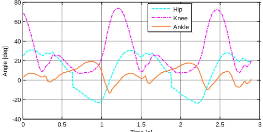
In Chapter 3, the previous results, including angular trajectories of the hip, knee and ankle joints in addition to the measured ground reaction, are used to derive an inverse dynamic simulation. Initially, human body modelling, inertia data and length specifications are provided. Then, the dynamic simulation is carried out by solving dynamic equations and through a Matlab SimMechanics model. Finally, the obtained actuation wrenches are presented.
Chapter 4 focuses on giving an approach based on interval analysis to design a CDPM for a desired workspace and a specific external wrench. First, the analysis of the workspace of
Abstract
the CDPMs is introduced, then an overview of the interval analysis method is presented. The wrench-feasibility of a CDPM’s equilibrium in its interval form is discussed, and the design algorithm is described. Lastly, the algorithm is illustrated through two different designs of a cable robot.
In Chapter 5, we address the design of the CDLT machine based on the results of the previous chapters. Then, the actuation mechanisms of the CDLM and the BWSD are calculated and selected. This chapter ends by presenting the CAD model of the gait trainer.
Introduction
Summary:
In this first chapter, a presentation of the required background for gait disorders, fundamentals of human movements and the anatomy of the lower limb are given. Then, we provide a description of the anatomy and physiology of the nervous system. Major causes of functional impairment such as gait disorders are spinal cord injury and stroke. These pathologies affect directly the functioning of the nervous system. After an injury, gait training is essential for the injured person to restore the gait function. An overview of different rehabilitation protocols is given. Then, a review on the development of the existing walking rehabilitation machines is addressed and a classification of these machines is performed. Amongst various devices, we adopt an architecture based on a cable robot
1.1. Introduction to Gait Disorders
In the everyday activities, walking is the most vital action to satisfy the well-being of a person. Loosing this function, decreases the quality of life, rises the dependence on others and puts individuals at a risk of falls and injuries. Frequently, neurological injuries lead to a partial paralysis that causes walking deficits, hence injured persons will suffer from long-life locomotion impairments.
Worldwide, Spinal Cord Injury (SCI) and Stroke neurological injuries are major causes for disability [1][2][3]. From 1950 to 2012, the global incidence of SCI varied from 8 to 246 cases per million population per year [4]. In the United States, the reported rate is about 40 cases and in European countries the incidence varied from 13.9 to 19.4 per million [5]. Likewise, stroke has an important impact, approximately every 40 seconds a stroke occurs in the United States and the reported annual rate is 795 000 incidents [6]. In the UK, the estimated rate is around 150 000 strokes occurring every year [3]. Worldwide, the prevalence, i.e., the cumulative number of strokes, was 33 million in 2010 [7]. In addition to SCI and Stroke pathologies, ambulation disability can be caused by non-traumatic injuries, i.e., neurological diseases such as Parkinson’s disease [8], multiple sclerosis and cerebral palsy [9].
It is thought that task-oriented, intensive and repetitive therapy have benefits in regaining walking ability [1][10] and hence enhance the patient’s quality of life [11][12]. The first goal of disabled patients is the rehabilitation of walking, specifically early gait rehabilitation is fundamental for a faster and efficient locomotion recovery [13][14]. Conversely, immobility during hospitalization promotes the risk of mortality and encourages
Chapter 1. Introduction
impairments [15] in addition to other side effects such as bone acceleration, sensory deprivation, isolation delirium and incontinence [16].
1.2. Biomechanical Background 1.2.1. Human movements
Motions of body segments can be described using a set of planes and directions defined relatively to the human body taken in standing position (see Figure 1). The planes are three: the frontal, the transverse and the sagittal planes. The frontal (coronal) plane is positioned vertically and it divides the body in anterior and posterior parts. The transverse (horizontal) plane lies horizontally and splits the body into inferior and superior portions. The sagittal planes are situated vertically, dividing the body into right and left sides. The midsagittal plane is positioned at the midline of the body and the parasagittal plane is a midsagittal parallel plane [17][18][19]. Moreover, standard directions are described by the following paired terms: superior/inferior, anterior/posterior (ventral/dorsal) and left/right (medial/lateral) (see Figure 1).
Figure 1: Planes of the human body [20].
The human body is characterized with a set of articulated segments, each segment has a proximal and a distal ends, which are, respectively, the closest and the farthest points to the segment’s attachment point. Body parts are articulated to form joints rotational motions are classified according to the axis of rotation that passes through the articulation’s center. The most common angular movements are: flexion/extension, abduction/adduction and internal/external rotations [17][18][19].
The flexion/extension are the movements that take place in the sagittal plane. Flexion occurs when bringing two segments closer to each other or when a limb moves forward (along
the anterior axis) and extension is the rotation in the opposite direction of flexion. Moving a joint backward beyond its normal range is called hyperextension (see Figure 2(a, b)).
Abduction/adduction are the movements of a segment in the frontal plane. Abduction is the motion when a part goes away from the body midline superior/inferior direction. Conversely, Adduction is defined when bringing two segments together (see Figure 2(c, d)).
Internal/external (medial/lateral) rotations occur when a segment revolves around its own longitudinal axis. Internal rotation is the movement when turning toward whereas external rotation is when turning away (see Figure 2(e)).
Yet, there are special movements that have specific names and occur only at certain joints, such as dorsiflexion/plantar flexion and inversion/eversion of the foot (see Figure 2(f)).
Figure 2: Types of angular movements [18][19]. 1.2.2. Anatomy of the lower limb
The lower limb is the biomechanical mechanism that have two main functions: support of body weight and locomotion. It is composed of four main segments: the pelvis, the thigh, the leg and the foot (see Figure 3). Note, the leg is commonly known as the shank or the calf. The lower limb is a weight bearing system, then its bones are stronger than other bones of the skeleton system. Furthermore, its skeleton contains 31 bones per limb. The pelvis is formed of two hip bones called also coxals. The unique bone of the thigh is the femur which is the longest and strongest bone of the skeleton system. The leg contains two bones: the fibula and the tibia. Bones of the foot are in three rows: a first row of 7 tarsals, a second row of 5 metatarsals and a third row of 14 phalanges [21]. The forefoot consists of metatarsals and phalanges [21].
Chapter 1. Introduction
In anatomical terminology, while the superior face of the foot is called dorsum, the inferior face is named sole of the foot. Moreover, the posterior and the anterior parts of the foot are called, respectively, the heel and the toe [21].
Leg Foot Femur Patella Tarsals Metatarsals Fibula Tibia Hip Bone Thigh Hip joint Knee joint Phalanges Ankle joint Pelvis
Figure 3: Anatomy of the lower limb [18].
Sites where skeleton rigid links meet each other are called joints or articulations. Several types of joints can be they are. Functionally, articulations of the lower extremities are classified as freely movable (diarthrosis), and structurally, they are known as synovial joints. Indeed, they contain a fluid-filled cavity, and ends of the bones are covered with an articular cartilage. The joint cavity is enclosed with two layers: a synovial member and a fibrous capsule. The fluid and the cartilage lubricate these freely movable joints [19].
The lower extremity includes 4 synovial joints: the hip, the knee, the ankle and the foot [21]. The hip joint is a ball and socket type of synovial joint formed by the acetabulum of the hip and the spherical head of the femur. The hip joint is a spherical joint then rotational movements occur in all axes. Figure 2(a), Figure 2(c) and Figure 2(e) show, respectively, Flexion/Extension, Abduction/Adduction and Medial/Lateral motions of the hip joint.
The knee joint is the most complex joint in the body, it is a modified hinge variety of a synovial joints. The knee includes surfaces of 4 bones: the femur, the tibia, the fibula and the patella. The patella bone (or knee cap) is placed in front of the joint (see Figure 3). The major occurring movement is the flexion/extension (see Figure 2(b)), but some medial/lateral rotations are permitted [18].
The ankle joint is a strong weight-bearing hinge joint. The inferior ends of the tibia and the fibula, and the talus of the foot meet to form this articulation. The only possible motion is the Dorsiflexion/ Plantar flexion (see Figure 2(f)).
In addition to all above joints, the various bones of the foot include numerous joints. Such articulations include intratarsal, tarsometatarsal, intermetatarsal, metatarsophalangeal, and interphalangeal joints [21]. For example, the intratarsal joint allows the Inversion/Eversion movement of the foot (Figure 2(f)).
1.3. Understanding Spinal Cord Injury and Stroke 1.3.1. The nervous system
An understanding of the anatomy and physiology of the nervous system (NS) is substantial to explain SCI and Stroke, since these neurological injuries affect directly the functioning of the NS.
Human body motions are controlled by the NS which have 2 parts: the Central Nervous System (CNS) and the Peripheral Nervous System (PNS) (see Figure 5) [19]. The CNS includes the brain and the spinal cord, and the PNS comprises nerves that extend from the brain and the spinal cord, i.e., located outside the CNS. The spinal cord and nerves consist of pathways to transmit information as an electrical signal between the brain and the sensory receptors/effector organs. Neuron or nerve cell is the basic structural unit of the NS. Further, a neuron is a cell that transmit information as electrical impulses between body parts [19].
Chapter 1. Introduction
Figure 5: Main divisions of the nervous system [22].
The brain is located in the skull and has 4 parts: cerebrum, cerebellum, diencephalon and brain stem (see Figure 6) [19]. The cerebrum is the biggest part of the brain (83% of total brain mass) and is made up of two communicating hemispheres. Functionally, this part controls all sensory and motor functions, thought processes and memories. The left cerebral hemisphere is concerned with sensory/motor functions of the right side of the body and vice versa. Similarly to the cerebrum, the cerebellum has two hemispheres. Functionally, it initiates subconscious movements like walking and coordinates muscle movements of the human body, and hence helps in controlling posture and equilibrium. The diencephalon consists of a relay station that dispatches sensory/motor pathways to and from the brain. In addition, it has an area that controls: various vital functions (e.g. eating, drinking and temperature regulation), endocrine system and autonomic functions. The brain stem is a connection with the spinal cord and it controls: the movements of the neck and the head through cranial innervation and involuntary functions necessary for surviving like breathing and heart rate regulation. In summary, the brain has different identifiable regions [22], each one has a specific function (see Figure 7). An injury that may happen to the brain can disturb sensations, movements and thoughts, and even can cause death [22].
Figure 6: The brain and it is main parts [19].
Figure 7: Main functions of the different areas of the brain [23].
The second part of the CNS is the spinal cord which lies within the vertebral column, it consists of a bidirectional pathway between the brain and the peripheries (i.e. skin, joints and muscles) of the human body via spinal nerves, which are part of the PNS. The spinal cord innervates the neck, limbs and trunk through 31 pairs of spinal nerves roots, they are divided into 5 regions: cervical, thoracic, lumbar and coccygeal. Each group of spinal nerves has a specific destination to a periphery, Figure 8 depicts the locations and the functions associated with spinal nerves, e.g. the movements of the lower limb are controlled through the L1-S1 innervations. Incoming sensed information is sent to the brain through ascending tracts (i.e. nerves), and outgoing motor information is carried to periphery via descending tracts [19]. Furthermore, the spinal cord acts as a reflex center, i.e., produces involuntary responses.
Chapter 1. Introduction
Transection of the spinal cord result in a permanent loss of sensation and paralysis of voluntary movements [18].
Figure 8: The spinal cord [24].
The PNS includes the parts of the NS that lies outside the brain and the spinal cord, i.e., the CNS. More precisely, the PNS consists mainly of both: cranial nerves and spinal nerves, i.e., nerves that extend from the brain and the spinal cord, respectively [18]. These nerves are the communication pathways between the peripheries and the CNS. The peripheries include sensory or afferent nerve receptors such as receptors found in the skin, joints and muscles, and motor or efferent motor nerves such as skeletal muscles and glands.
To sum up the physiology of the NS, sensory receptors of the PNS sense the internal and external environment (e.g. blood pressure and touch). Afferent signals are carried to the CNS that analyses information, makes decisions, and sends commands. Afferent signals from the CNS are carried away to the organ effectors (e.g. muscles and glands). Therefore, the NS is the communication and control system of the human body [19]. If this system is attained by an impairment or a damage, a disability may occur and a rehabilitation strategy is required to restore the lost functions.
1.3.2. SCI and stroke pathologies
SCI and stroke are neurological pathologies that disrupt the physiology or the functioning of the NS. They are damages that dysfunction, respectively, the spinal cord and the brain.
A SCI is a damage to the spinal cord that affects motor, sensory and autonomous functions of the human body [10][25]. It results from both traumatic and nontraumatic causes. Traumatic SCI happens due to a physical impact such as accidents, vehicle crashes, violence, falls and so on. A nontraumatic SCI results from poor health condition like infectious diseases and tumors that may affect the spinal cord [24].
Lesion (damage) to the spinal cord may destroy signals traffic to/from the brain and it can lead to a dysfunction of movement control even if muscles are valid. Lesions to the spinal cord are classified by the Neurological Standards Committee of the American Spinal Injury Association (ASIA), standardization is in the aim of providing rigorous information between clinicians and research fields [25]. A SCI may be complete if there is no preservation of sensory and motor functions at S4-S5 region of the spinal cord, whereas an injury is said to be incomplete if any sensory and/or motor function is preserved below the neurological level including the sacral segment (S4-S5) [25]. Moreover, lesions can be at different regions of the spinal cord. The higher the region of damage is, the greater impairment will be. Cervical SCI is defined as tetraplegia, it causes paralysis in the four limbs, the trunk and the pelvis. Damage in the thoracic, lumbar or sacral regions is called paraplegia. Where the trunk, legs and pelvis are involved with an impairment depending on the level of injury [25].
Figure 9: Illustration of stroke causes [23]: a) Ischemic stroke, and b) Hemorrhagic stroke.
Another important cause of long-term disability is Stroke, known also as CerebroVascular Accident (CVA). It occurs when blood supply to an area of the brain is blocked or burst [23][26]. Without oxygen and nutriments, brain cell starts to die within minutes. A Transient Ischemic Attack (TIA) called also mini-stroke takes place if blood supply
Chapter 1. Introduction
is disrupted for a short time, a TIA is a warning for a Stroke. There are two types of stroke: Ischemic Stroke and Hemorrhagic Stroke (see Figure 9). The first subtype is the most common, indeed about 85-90% of strokes are ischemic [3] and it happens when a blood vessel (artery) is occluded. The second one happens if a blood vessel is burst and blood spoils around the brain. Depending on the function of the damaged location of the brain (see Figure 7), effects of a stroke are: pain, depression, decrease of sensory/motor function, memory problems, vision weakness … Hence, walking ability may be deteriorated or lost. On a one side of the human body, a motor weakness is called hemiparesis, while a complete paralysis condition is called hemiplegia [27]. After a stroke, 20% of patients became dependent to wheelchair and about 70% are able to rewalk with a reduced performance [28].
After a SCI or a Stroke, on top of primary effects of injury, health condition degeneration such as cardiovascular disorders and musculoskeletal deterioration is another complication for disabled subjects. Therefore measures for an early and effective rehabilitation strategy is substantial [11][12].
1.4. Gait Rehabilitation
1.4.1. Rehabilitation after a neural injury
The fundamental truth for the foundation of rehabilitation is that the NS can acquire new skills and learn by experience [29]. However, rehabilitation can be explained by the mechanism of neural plasticity, which is the neural adaptations and changes in neural circuits to gain a motor skill or to manage a cognitive task [29]. After a CNS or PNS injury, this intrinsic biological evolving and adaptability within the NS, enhances motor function recovery and lessens impairment. Locomotor training is based on the principal “train like you walk”, neural plasticity is linked to the nature of the practiced activity. This approach is known as activity-dependent plasticity which is the enhancement of learning of the neural circuitry in response to the intensive practice of a specific movement which is in our case walking [27]. Patients who practice activity-dependent plasticity, can learn more potentially and hence, gain more effective functional recovery
Furthermore, the neurorehabilitation of walking is explained by the stimulation of neural circuits responsible of locomotion control [30] commonly called central pattern generator (CPG) which is an intrinsic capability of the spinal cord [31][32][33]. The CPG, located at the spinal cord, is a neural network that generates Spatio-temporal information of rhythmic or stepping movements such as walking or swimming. Thus, gait training consists in
stimulating neural activity, and consequently enhancing neural plasticity of neural center of locomotion.
In summary, for neurological deficits where motor/sensory functions are partially preserved, intense training program could encourage the restauration of ambulatory function. After an injury, regeneration and repair of the nervous system occur spontaneously and is enhanced by undergoing a training therapy [10]. Thus walking relearning or restoration of locomotion is gained naturally, and in response to a rehabilitation treatment.
After a neural injury, Task-specific rehabilitation should begin early as soon as possible in order to maximize the potential of gait restauration by accelerating neurological adaptations or neuroplasticity [34]. Developing effective gait training program is the first challenge of rehabilitation specialists. In general, after a neural injury onset, the overall gait rehabilitation process follows three phases: i) mobilized of inpatients into wheelchair as soon as possible, ii) restauration of walking function and, iii) improvement of gait quality [35][36]. To promote locomotion rehabilitation, many approaches have been developed: conventional over-ground training, body weight support (BWS) training, body weight support treadmill training (BWSTT) and robotic-assisted technology [27][29].
1.4.2. Therapist-assisted rehabilitation of walking
Conventional over-ground gait training can only begin if the patient has sufficient strength to stand up in parallel bars or in a hemibar [27][29]. Before being able to sustain in an upright position, therapy starts with some activities in a lying posture, such as passive rotation of the hip, knee and ankle joints. These activities aim to strengthen weak muscles and rise the range of motion of stiff joints. Further, developing various body postures such as sitting and standing balance is important to improve impaired balance [29]. Once enough endurance and stability for standing in parallel bars, therapists assist patients to control torso posture and lower limbs movement. Thereby, one aims the improvement of balance and weight-bearing during gait. In the meanwhile, the patient is asked to practise some single movement of the gait cycle, then as recovery progresses, more complex movements are introduced [37]. Beside physical help, providing verbal instructions is also essential to shape the pattern of gait [29]. For both: stroke and SCI patients, intensive training has promoted walking function recovery [38][39][40][41]. However, conventional treatment requires large assistance of physiotherapists due to the important workload of the rehabilitation task. As a consequence, duration of training is limited which may reduce the effectiveness of walking recovery process.
Chapter 1. Introduction
To help patients to stay in upright position, a BWS system was introduced [42]. Thanks to BWS, patients who are unable to fully weight bear, can benefit for an early training in secure and safe condition, consequently far from the risk of falls. A basic BWS device includes an overhead harness to be worn by a patient and a mechanical frame with a counterweight system [43][44] (Figure 10(a)). The BWS provides an easy balance control and reduces gravitational forces which facilitates the practice of stepping movements. Thereby therapists focus only on assisting leg’s motion more than assisting balance control.
BWS can be used for overground training [43] (Figure 10(a)), but for a more practical rehabilitation, BWS is usually carried out using a treadmill (Figure 10(b)). This method is known as Body Weight Supported Treadmill Training (BWSTT) which is the technical translation of task-oriented training. Severely injured patients with limited voluntary motor function can benefit from an intensive gait training resulting in enhancement of training-induced neural plasticity of the CNS [27]. One shall note that the word partial is often used with BWSTT since the amount of unloading can be adjusted [45]. The amount of BWS is high in the beginning of therapy and as walking capacity evolves, the amount is decreased gradually [46].
For a hemiparetic person, while be suspended through a harness over a treadmill (see Figure 10(b)), one clinician provides assistance to pelvic rotation movements and another clinician guides foot placement [27]. In the meanwhile, various parameters can be adjusted such as the level of weight support, walking speed and temporal specifications of the gait cycle [29]. The action of the BWS can be cancelled if the patient reaches a full weight bearing, then treadmill speed is gradually increased as walking ability progresses.
The BWSTT facilitates the task of clinicians to provide a regular gait pattern, as close as possible to the natural gait pattern. Moreover, acute SCI and chronic Stroke patients can benefit for an early and safe training. Postural stability is given by the BWS and the regularity of gait pattern is promoted by the treadmill. Viewed as a task-specific practice, BWSTT has been demonstrated a good improvement of motor function for overground locomotion compared to conventional treatment [47][48][49][50].
Furthermore, therapist-assisted BWSTT is a secure and effective strategy for gait training. Many studies has confirmed improvement of walk speed, endurance and walking ability [27][51][52]. However, this approach is still limited by the performance of assistants and physically-demanding due to intensive labour work. Depending on the severity of injury, up to 3 assistants may be needed to ambulate disabled persons [45].
1.4.3. Robotic-assisted rehabilitation of walking
During a BWSTT, the use of assistive devices such as robotic systems is very helpful by giving prolonged and regular task-oriented training, thereafter enhancing motor recovery. Compared to Therapist-assisted BWSTT, robotic-assisted training promotes recovery of ambulation by increasing the total duration of therapy and decreasing the labor and intensive workload [45]. For Manual-assisted training, sessions are limited by the physical performance of the trainers, and further, spatio-temporal specifications of the gait cannot be reproduced faithfully. On the contrary, automated machines replicate the task of therapy continuously, accurately, and consistently. Further, gait parameters can be adjusted precisely. All these advantages contribute to enhance learning capacity and should lead to a more effective gait recovery [45][53][54][55][56].
Design and development of rehabilitation robots have been began since the 1960s [57]. For gait training, Several types of robotic-assisted systems have been developed, their design outlines focus on suspending patients and assisting the motion of legs [36]. Mainly, such system are made out of: i) a mechanized BWS with controllable body weight unloading [46][58][59][60][61][62][63], ii) actuated orthoses with programmed gait trajectories, to be attached to the lower limbs, and iii) with or without a treadmill to emulate the overground walking. These machines aim to provide a physiological gait pattern with both: a minimum intervention of therapists, and adjustable gait parameters such as walk speed and the amount of unloading.
The basic control strategy of gait training consists on reproducing the walking pattern regardless of the participation of patients, i.e., guiding movement on fixed gait trajectories. This
Chapter 1. Introduction
position control strategy is largely implemented in robot-assisted gait trainers, it consists of a control system that tracks joint angles and applies motor torques with reference to normative gait trajectories obtained from experiments [64][65]. Conversely, an important determinant in gait training of a wide range of neurological injured patients is the voluntary effort and the active participation of a subject to achieve a movement [64][66]. Control strategies that take into account forces produced by patients are known as patient-cooperative approaches. In the literature, the terms: patient cooperative, assist as needed, compliant, force-controlled, adaptive and interactive robots are used to design patient’s involvement in gait training [66][67][68]. Cooperative approaches are introduced by employing impedance and adaptive control systems [64][66].
Structurally, robotic devices can be distinct into 2 forms: first there are the powered exoskeletons: a serial robot attached to the thigh and the leg, and second ones are devices that use movable footplates to drive the feet. Another possible form is similar to the first one, but powered orthosis are substituted with flexible elements such as cables.
Among various trainers from the first form we cite: The Lower Extremity Powered Exoskeleton (LOPES) [67], the Ambulation-assisting Robotic Tool for Human Rehabilitation (ARTHuR) [69], the Active Leg Exoskeleton (ALEX) [70], the Pelvic Assist Manipulator and the Pneumatically Operated Gait Orthosis (PAM /POGO) [71], Lokomat [72], LokoHelp [73], ReoAmbulator [74]. And from the second type, we mention: The Gait Trainer (GT) [75], the haptic Walker [76] and the gait robot G-EO [77].
The LOPES system designed in the University of Twente (Enschede, The Netherlands) combines a 3 DOF pelvic support, and a 3 DOF exoskeleton for each leg [67]. The pelvic support has two actuated horizontal motions along posterior/anterior and medial/lateral directions. However, the superior/inferior displacement is kept for free motion. The vertical displacement of the pelvis is weight compensated using a spring mechanism, i.e., a suspension system. Connected to the pelvis support, each leg’s exoskeleton has two rotations at hip joint (flexion/extension and Abduction/ adduction), and one rotation at the knee. The ankle joint is left free Thus the mechanism has a total of 8 actuated joints and one passive DOF. In addition, the LOPES includes a treadmill to achieve walking. Upright standing and balance control have to be carried out by the patient.
Interaction between the LOPES and the patient is achieved through an impedance control. For that, the active joints consist of elastic actuators made out of Bowden cables. Indeed, two operational modes can be selected: “patient-in-charge” and “robot-in-charge”. For the first, the LOPES follows patient in unconstrained movement and for the second, the system
guides the patient for a prescribed gait pattern. The Evaluation of the LOPES with healthy persons in “patient-in-charge” mode during a free walking showed a pattern close to a free treadmill walking [67]. A new LOPES system (Figure 11(a)) was designed including a BWS system [65][78], a clinical trial has showed positive therapeutic outcomes in training four out of five stroke subjects [78].
Figure 11: (a) The new LOPES system [65], (b) The Alex prototype [70], and (c) Diagram of the ARTHuR gait trainer [69].
The active leg orthosis ALEX (University of Delaware, Newark, The USA) [70], conceptually based on the passive Gravity Balancing Leg Orthosis [79][80], combines a trunk orthosis and a leg orthosis (Figure 11(b)). The first part is a partial weight support device that keeps the patient stable on a treadmill through a harness system and it has 4 passive DOF held with springs. The second part embodies two linear actuators to actuate the hip and knee joints in the sagittal plane. To allow interaction with patients, the ALEX relies on the use of a force-field controller. In contrast to the LOPES, ALEX uses friction compensation method in place of series elastic actuation to achieve backdrivability of the device [81]. Thereby, training is based on the “assist as needed” approach in which the robot assists or resists the leg’s motion on a desired trajectory [70]. By training two stroke patients, improvement of gait pattern including walking speed and joint excursion was reported [82].
The ARTHuR consists of two horizontal linear motors that drive two linkages connected at their ends [69] (Figure 11(c)). The end-effector can be attached at the knee or the ankle in order to move the lower limb. Interaction with legs is possible through the use of linear motors that have low backdrive friction and can exert substantial force. Training is based on teach and replay technique, consisting in recording motion during manual assistance and then replaying
Chapter 1. Introduction
it during robotic-assisted training. Evaluated on SCI patients, ARTHuR has demonstrated a reliability to replay trainer-induced stepping movement [83].
Designed at the University of California (Downey, USA), The PAM/POGO is a pneumatic trainer able to be compatible for full range of natural gait movement of both: the pelvis and the legs (see Figure 12(a)) [71].The Pelvic Assist Manipulator (PAM), used to assist the pelvic motion, is a two 3-DOF robotic segments, each one has three pneumatic cylinders assembled in a tripod configuration. Compliant with the PAM, the Pneumatically Operated Gait Orthosis (POGO) is a pneumatic device (2 cylinders per leg) that actuates the hip and knee joints in the sagittal plane. The PAM/POGO is a force controlled system, in fact it is capable of producing large force with a lightweight moving parts, .i.e., the system is backdrivable. Therefore, the system is able to drive the patient through a reference trajectory. Initial experiments with SCI patient were achieved successfully [71].
Figure 12: (a) Experimental setup of the PAM/POGO [71], (b) Lokomat system (picture courtesy of Hocoma AG [84]), and (c) ReoAmbulator (picture courtesy of Motorika Ltd. [85]).
The Lokomat trainer (Hocoma AG, Volketswil, Switzerland) is made out of a Driven Gait Orthosis (DGO), a counterweight BWS and a treadmill [72]. On one hand, the suspension system combined to a rotatable parallelogram mechanism, stabilises the movement of patient’s torso in vertical direction and produces a weight unloading. On the other hand, The DGO drives the thigh and the leg, respectively, at the hip and the knee. Joints actuation is conducted through DC motors and linear ball screws. The ankle joint is stabilized using a foot-lifter made of elastic straps. The controller of the Lokomat synchronizes the speed of the treadmill and the speed of the DGO to generate a gait-like pattern. The extended version of the Lokomat (see Figure 12(b)) includes advanced features such as: i) impedance-control allowing assist as needed training
[66][86], ii) optional module allowing pelvis lateral displacement and hip abduction/adduction, and iii) augmented visual feedback [87].
The electromechanical gait device Lokohelp operates with a double side levers device , a BWS system and a motor-driven treadmill [73]. The treadmill plays a double function: emulation of overground walking and a driver for the levers device. For each leg, an orthosis stabilizes the ankle joint and has to be connected to one lever that transmits the gait pattern by following a mechanical track. Thereby, gait simulation is produced by guiding the ankles’ orthoses. The feasibility of the Lokohelp is confirmed by training patients with different neurological injuries, in fact likewise manual BWSTT, same improvement is observed using the LokoHelp machine [73][88]. A main limitation of this device is that generated gait shape is constrained mechanically, and hence cannot be adjusted.
Similar to the Lokomat, The ReoAmbulaotr/Autoambulator (Motorika Ltd., USA /HealthSouth Corp., USA) [74] is a BWSTT powered gait orthosis (see Figure 12(c)). Simulation of walking is carried out using two robotic arms (i.e., exoskeleton). Each arm has two DOF (for hip and knee joints) and has to be strapped at the thigh and the ankle. Moreover, a lifting mechanism (.i.e., a BWS) suspends and holds the patient over the treadmill [74]. Significant improvement was reported following the treatment of hemiparetic stroke patient [89].
Now moving to the second type (movable footplates) of gait restauration systems. The Gait Trainer I (Reha-Stim GmbH /Free University, Berlin, Germany) drives the lower limb by moving the sole of the foot [75]. The patient is secured by a harness system and positioned over footplates (Figure 13(a)). The gait pattern is produced by a planetary gear system, simulating foot motion during a gait cycle. In addition, vertical and horizontal motions of the patient’s CoM are controlled via ropes attached to the harness. Advantages of such system is that no constraints are putted on the hip and knee joints. Further, physical therapists can apply corrections to the motion of the knee (Figure 13(a)). Although operating in position control with the lack of any force control [90], multiple evaluations including the largest clinical study DEGAS [91] have confirmed the effectiveness of the Gait Trainer I [91][92][93].
Chapter 1. Introduction
Figure 13: (a) the Electromechanical Gait Trainer [90], (b) The HapticWalker walking simulator [90], and (c) the gait robot G-EO [94].
In contrary to the Gait trainer which provides pure passive guiding, the HapticWalker [76] and the gait robot (G-EO) [77] have two freely programmable 3 DOF footplates. This feature allows training patients for repetitive daily life walking situations such as stair climbing. The HapticWalker is a redesign of the Gait Trainer I aiming the achievement of high dynamics and arbitrary motions [76]. This machine is a heavy robot manipulator driven by powerful electric drives to reach high speed movements. Each foot platform includes a six DOF force/torque sensor allowing the measure of the interaction with a patient. Preliminary trials with stroke and SCI subjects are encouraging. Further, evaluations are under-going [90][95].
The G-EO (Reha Technologies, Bozen, Italy) was designed to train stroke patients [95], its mechanical structure is smaller than the HapticWalker. In addition to feet actuation, the patient’s CoM is controlled in vertical and lateral translations. Tests with simulated floor walking and stair climbing showed comparable muscle activation between real and simulated movements, which confirms the feasibility of the G-EO in training stroke patients [77]. Moreover, an adaptive control strategy is implemented by measuring foot reaction forces via a pair of overshoes [96]. Seeing that main drawback of footplates-based trainer is the lack of true swing phase since the foot is in permanent contact with the machine [96], the adaptive algorithm allows a natural gait simulation by controlling the resistive force of the footplates.
Amongst all above described training machines, only five of them are commercially available: the Lokomat, the ReaAmbulator/AutoAmbulator, the Lokohelp, the Gait Trainer I and the G-EO. Clinical trials in stroke patients reported the superiority of the Lokomat and the Gait Trainer I in gait function recovery [77].
1.4.4. Cable based system for gait rehabilitation
Aforementioned exoskeleton type and movable footplates form machines have been largely studied and evaluated. Further, they are effective and reliable for gait training [36][57][64]. However, such systems are heavy, bulky and potentially dangerous, consequently they require complex safety techniques. Since rehabilitation is based on a pure interaction with patients, development of patient-friendly rehabilitation robots is substantial [97]. Safety, reliability and flexibility are high-demanding standards for robot-aided rehabilitation devices.
Widespread of current rehabilitation machine is hindered by their expensiveness. For example only 600 Lokomat units have been sold since 2001 [84], the price is about 300 000 $ per unit [98]. As consequence, many patients will be unable to receive an adequate therapy and conversely by using low cost gait trainers’ multiple machines may be installed within a clinic. Consequently, development of rehabilitation devices should make a priority for simple and cost-effective designs.
In this context, cable robots have promising features including lightweight structure, large reachable space, low cost and easy setup. Thus, integration of cable robots into rehabilitation machine could be very advantageous [99][100].
Moreover, features such as lightweight and high dynamics [101] promote the backdrivability of the machine, thus assist-as-need approach can be easily implemented. One shall note that compliance paradigm is essential with hemiparetic stroke subjects since patient has one valid leg and one paretic leg. Patient-cooperative training appears to be more suitable than fixed trajectory control strategy since the first one encourages active and voluntary involvement of patients during gait training [99].
Another possible advantage of cable robots is the simplification of the setup procedure to start a training session. For the exoskeleton type machine, an alignment of patient’s joints and the robotic arm joint is substantial which is not required for cable robot, thus the setup is easier and shorter using CDPM [99].
Based on wire technology, the first system that addresses rehabilitation of walking is the MAN [102], developed at Fraunhofer Institute IPK (Berlin, Germany). STRING-MAN is a dynamically controlled weight-suspension and posture control support for the practice of treadmill gait training. The first design had a mechanical configuration of 7 cables (see Figure 14(a)) that drive the trunk and the pelvis by mean of a harness worn by the patient. Thus, the robot can be described as a 6 DOF system for posture control and partial weight bearing. Each wire is connected to the patient via a pulley and is actuated by a linear drive. The STRING-MAN is equipped with a powerful sensory system allowing its interaction with
Chapter 1. Introduction
subjects. Such sensors are: foot gait phase detection sensor, reaction force sensing (foot forces) and zero-moment point (ZMP) estimation sensor, knee-goniometer, wire force and linear actuator position sensors, as well as pulley rotation sensors [102].
Wire sensors are used to measure Cartesian body position and Cartesian body forces including the amount of weight bearing. Further, integrated sensors allow detection of different gait phases, and possibly an abnormal walking.
Figure 14: (a) Experimental setup of the STRIN-MAN system [100], and (b) Concept of the SMART-STRING system [100].
The control algorithm includes a robust position-based impedance controller and a force controller. These controllers are substantial to control the robot-human interaction allowing the support of patient voluntary initiative. Further, the system can be tuned from totally passive to completely active. However, human body motion cannot be well estimated due to geometric uncertainties, harness elasticity, flexibility of wire’s attachment point. In fact the robot is never controller in position mode [100]. Moreover, safety measures are critical and require improvement.
First experiments have been performed with dummies and healthy subjects. For weight balancing reasons, it was observed that satisfactory results could be obtained using a 3 DOF/4 wires configuration. Besides, to actuate the lower limb 3 wires per leg may be added. To improve the actuation technology, it was proposed to actuate wires using a Pneumatic Artificial Muscle (PAM). This concept is called SMART-STRING (see Figure 14(b)).
As a second system, the Cable-driven Locomotor Trainer (CaLT) is a compliant robot, i.e., generates controlled forces on the legs [103]. This device uses the technique of counter-weight BWSTT combined to a cable robot to drive the lower limbs. Each leg is driven by two cables through an attachment around the ankle (Figure 15). Four spools coupled to motors drive the 4 cables via pulleys. Torque load cells are inserted between motors and spools to record the applied torques. Further, to get the position of the ankle, a custom three dimension sensor is used. This architecture allows to control the assistance/resistance force during locomotor training. In fact, the cable robot can be moved with minimal resistance force, i.e., the system is highly backdrivable. Therefore, the robot can assist stepping movement if patient is unable to step forward during treadmill walking. Feasibility of the CaLT was carried out by training fourteen stroke subjects and nine SCI individuals. Results have showed significant changes in walking capacities with both type of patients. It was found that the CaLT system is feasible in training people with stroke and chronic SCI people [99].
Figure 15: Description of the CaLT gait trainer [103].
Eventually, based on rigid links, classical rehabilitation devices are heavy, expensive and fairly ergonomic. Conversely, Cable robots have various promising features including low inertia, ability to reach high speeds, low fabrication costs and easy to setup. Moreover, such robots are highly backdrivable and compliant which allows to implement assist-as-needed training paradigm. Up to now, there are no market available wire-based gait training machines. Ongoing developments aim to exploit benefits of wire robots while overcoming some limitation such as various geometric uncertainties and tensionability constraints [99][101].
Chapter 1. Introduction
1.5. Design of the Cable-Based Gait Rehabilitation Machine
In this work, we propose a machine based on a CDPM, called the CDLT. It includes: a Body Weight Support Device (BWSD), a Cable-Driven Leg Manipulator (CDLM) and a treadmill (T). A new orthosis was designed to be attached to the leg and it is controlled by a cable system to move the lower limb. The number of cables was chosen in a way to totally restrain the movement of the orthosis in the sagittal plane. This design comes with all the benefits of cable driven robots. Hereby, a diagram of the CDLT is presented in Figure 16.
Winch (W) Spring (S) Pre-tension motor (P) Harness (H) Static pulleys Spooling motor (Sp) Treadmill (T)
Body Weight Support Device (BWSD) Cable-Driven Leg Manipulator (CDLM) Dynamic pulley Rope Orthosis (O) Mechanical stops (M) Mean position Footlifter (F)
Figure 16: Mechanical description of the proposed gait training machine.
As included in all gait rehabilitation devices, this design comprises a BWSD made out of elastic springs. In the literature, there are various architectures for BWS [46]:
i)-Static System (Figure 17(a)): in such mechanisms, the harnessed patient is lifted using a basic winch (Figure 17(a)). The spooling action can be made manually or using an electric motor. The desired unloading is proportional to the lifted distance. More sophisticated systems integrate a force sensor to help in adjusting the amount of unloading. Irregularity of the weight support and restrictions of the pelvic vertical displacement are the major drawbacks of static devices.
ii)-Passive Dynamic Counterweight System (Figure 17(b)): unlike static systems, in this case, the patient is unloaded by means of a mass that produces a gravitational counterforce. During a gait, changes in counterweight acceleration yield inconsistent unloading.
iii)-Passive Dynamic Elastic System (Figure 17(c)): The suspension force is generated by a set of springs or other elastic elements. Thus, the amount of unloading is proportional to the tension in the springs, when the inertia of the moving parts is neglected. The unloading force is relatively stable since it follows the variation in the spring length. The use of long springs with low stiffness can lessen force rippling. A patented design [104] showed that more suitable results are provided by adding an extra elastic force exerting element in a way to compensate the deviation in the main force.
iv)-Active Dynamic System (Figure 17(d)): Similar to the previous system, the integration of an active force generating mechanism allows to eliminate the variations in the suspension force. As an example, the active Lokolift system [46] produces this compensation force through a closed loop between a force sensor and an electric drive. Such system produces a relatively constant unloading, further it performs a rapid change between different BWS values. Compared to the aforementioned BWS devices this one is relatively more complex.
The passive elastic BWS is widely used in training machines, it offers good results with respect to a simple and basic mechanism. A similar mechanism called the BWSD is included in The CDLT (Figure 16).
(a) (b) (c) (d)
Figure 17: Common body weight support systems [46]: (a)Static BWS: a simple winch, (b) Passive dynamic BWS with adjustable counterweight, (c) Passive dynamic BWS with elastic
spring, and (d) Active dynamic BWS with force-control loop.
The unloading force is transmitted from the BWSD to the patient through a cable, which is guided via a series of pulleys and attached to the harness (H). Major parts of the BWSD are two translational guided parts (see Figure 16). The first is equipped with a dynamic pulley to transfer the unloading force from the springs to the rope. Note that the movement of this part is
Chapter 1. Introduction
limited by two mechanical stops. The second one is coupled to a power screw driven by a motor (P). The two sliding parts are connected with springs (S). The pre-tension motor (P) controls the position of the lower sliding part, and hence adjusts the springs pre-tension. Thereby, the amount of unloading is selected. The electric winch (W) spools the rope to lift the patient from a sitting to a standing position, further it allows the springs to work in a specific range.
The operational procedure of the BWSD is as follows:
i) The patient is secured by the harness in a sitting position, then we apply the desired amount of unloading throw the pre-tension motor (P). In such position, the upper sliding part is in contact with the lower mechanical stop.
ii) The patient is lifted until there is no contact between the patient’s feet and the treadmill. Here, the upper sliding part is in contact with the upper mechanical stop,
iii) The patient is lowered until the upper sliding wagon is lying in the middle of the two mechanical stops.
During walking training, the dynamic pulley moves alternatively around a mean position (Figure 16) following the variation of the vertical position of the patient. Meanwhile, the suspension force is produced by the springs’ tension, which is proportional to the instantaneous position of the dynamic roller added to the selected spring offset. One notes that a force sensor is required to measure the instantaneous unloading, and hence to adjust the desired amount around a mean value.
The second subsystem of the CDLT, which is CDLM, includes a 4-cables robot (see Figure 16). The moving platform is an orthosis (O) placed around the leg. In addition, a foot-lifter (F) is positioned between the orthosis and the foot in order to stabilize the ankle joint when the foot is off the ground (similar to the Lokomat system [72]).
The design of the leg’s orthosis is inspired from commercially available motion control knee splint. On one hand, the design involves the use of a wrap-around part that provides stability and comfort to the patient’s leg. On the other, the orthosis comprises two parts positioned at the anterior and the posterior sides (i.e., front and back) of the leg (Figure 18). Once, the two parts are placed around the leg, they are blocked using a fixation arm. This element has 3 passive DOF (2 rotations and one translation) to be tightened when the orthosis is mounted. The fixation arm allows to assemble the two parts as one unit and hence to keep the distances between the cable attachments as constant as possible. If these distances vary, the position control of the mobile platform will be erroneous since its geometry is not consistent.
Viewing that important ranges of motion are occurring in the sagittal plane, and for the sake of simplicity, the cable robot moves the leg in this plane using a set of 4 cables. In general, for a cable robot with n DOF, m=n+1 cables are required to totally restrain the movement of its effector [105]. The leg has 3 DOF in the sagittal plane, therefore, the orthosis is controlled by 4 cables. This will help to keep the orthosis in a given position and minimizes its sliding movement along the leg. Compared to the CaLT system (see Section 1.4.4.), the lower limb is moved using only two cable (see Figure 15), in a such configuration an upward force will be produced, pushing the ankle’s attachment to move along the leg.
The overground walking is emulated by employing a treadmill (T), producing the walk forward movement and applying the ground reaction force on the feet.
Conclusion:
A literature review on gait rehabilitation was given is this chapter. Robotized gait trainers enhance therapeutics outcomes when compared to the manually-assisted therapy. In fact, they are the technical translation of task specific and intensive training, which is substantial for an effective recovery of the gait function. Commercially available gait training machines are heavy and very expensive, which is an impediment to provide an adequate therapy for subjects with gait impairment. Cable driven robots could be a good candidate to achieve the task of rehabilitation, they are simple and less expensive. However, their design is challenging, since the tension in the cables has to be maintained positive at all times and cable interference has to be avoided during the motion.
An essential and required information in designing the CDLT is the kinematics and the dynamic of a normal gait. In the next chapter, a gait experiment will be carried out in order to get this information.
Analysis of Human Walking
Summary:
Evaluating and studying the performance of the CDLT requires the knowledge of the kinematics and dynamics of the lower limbs during a walk cycle. A quantitative gait experiment is performed to get this valuable information. A subject equipped with a set of reflective markers achieves a walking movement. The trajectories of the markers are recorded using cameras. This information is then used to calculate the orientation of the lower limb segments. A force platform is used to measure the reaction forces of the ground. Before giving the details of the experiment, a description of the gait cycle and its related terminology is given.
2.1. Overview of Normal Walking
A gait cycle (GC) is defined as a sequence of repetitive events, starting and ending with the same event. The two legs have the same series of events, with a phase shift of one half cycle [20]. A normal walk cycle has two main phases: Stance phase and Swing phase (see Figure 19). During stance time the foot is on the ground, over the swing time the foot is no longer in contact with the ground [106]. Further, the GC is also described with 7 successive events resulting in 7 periods: four of them occur during the stance phase and the three remaining make the swing phase (see Figure 19).
![Figure 5: Main divisions of the nervous system [22].](https://thumb-eu.123doks.com/thumbv2/123doknet/14583289.729570/16.892.209.661.102.554/figure-main-divisions-nervous.webp)
![Figure 7: Main functions of the different areas of the brain [23].](https://thumb-eu.123doks.com/thumbv2/123doknet/14583289.729570/17.892.214.681.402.754/figure-main-functions-different-areas-brain.webp)
![Figure 9: Illustration of stroke causes [23]: a) Ischemic stroke, and b) Hemorrhagic stroke](https://thumb-eu.123doks.com/thumbv2/123doknet/14583289.729570/19.892.137.763.653.968/figure-illustration-stroke-causes-ischemic-stroke-hemorrhagic-stroke.webp)
![Figure 17: Common body weight support systems [46]: (a)Static BWS: a simple winch, (b) Passive dynamic BWS with adjustable counterweight, (c) Passive dynamic BWS with elastic](https://thumb-eu.123doks.com/thumbv2/123doknet/14583289.729570/33.892.127.786.713.941/figure-common-support-systems-passive-adjustable-counterweight-passive.webp)
![Figure 22: Right leg (in gray) at [20]: (a) Heel rise, (b) Opposite initial contact, and (c) Toe off](https://thumb-eu.123doks.com/thumbv2/123doknet/14583289.729570/39.892.131.786.462.715/figure-right-gray-heel-rise-opposite-initial-contact.webp)
![Figure 24: Distance parameters of the gait cycle with reference to feet footprints [106]](https://thumb-eu.123doks.com/thumbv2/123doknet/14583289.729570/40.892.154.734.710.879/figure-distance-parameters-gait-cycle-reference-feet-footprints.webp)
![Table 1: Sagittal angular range of motion during flexion/extension motion trials [107]](https://thumb-eu.123doks.com/thumbv2/123doknet/14583289.729570/43.892.113.789.802.899/table-sagittal-angular-motion-flexion-extension-motion-trials.webp)