HAL Id: tel-03157373
https://hal.archives-ouvertes.fr/tel-03157373
Submitted on 3 Mar 2021HAL is a multi-disciplinary open access archive for the deposit and dissemination of sci-entific research documents, whether they are pub-lished or not. The documents may come from teaching and research institutions in France or abroad, or from public or private research centers.
L’archive ouverte pluridisciplinaire HAL, est destinée au dépôt et à la diffusion de documents scientifiques de niveau recherche, publiés ou non, émanant des établissements d’enseignement et de recherche français ou étrangers, des laboratoires publics ou privés.
par utilisation différentielle des systèmes de poussée.
Utilisation de méthodes de co-design
Eric Nguyen Van
To cite this version:
Eric Nguyen Van. Stabilité et contrôle latéral d’un aéronef à petite dérive par utilisation différentielle des systèmes de poussée. Utilisation de méthodes de co-design. Automatique / Robotique. Institut Supérieur de l’Aéronautique et de l’Espace, 2020. Français. �tel-03157373�
THÈSE
THÈSE
En vue de l’obtention du
DOCTORAT DE L’UNIVERSITÉ DE TOULOUSE
Délivré par : l’Institut Supérieur de l’Aéronautique et de l’Espace (ISAE)Présentée et soutenue le 23 Octobre 2020 par :
Eric Nguyen Van
Stabilité et contrôle latéral d’un aéronef à petite dérive par utilisation différentielle des systèmes de poussée. Utilisation de méthodes de
co-design.
Lateral stability and control of an aircraft equipped with a small vertical tail by differential use of the propulsion systems. Use of
co-design methods.
JURY
M. Isabelle Fantoni Directrice de Recherche Examinatrice
M. Mark Lowenberg Professeur des Universités Rapporteur
M. Franck Cazaurang Professeur des Universités Président du jury, rapporteur
M. Philippe Pastor Enseignant Chercheur Encadrant de thèse
M. Carsten Döll Ingénieur de Recherche Co-Directeur de thèse
M. Daniel Alazard Enseignant Chercheur Directeur de thèse
École doctorale et spécialité : EDSYS : Automatique 4200046 Unité de Recherche :
ONERA - The French Aerospace Lab - Traitement de l’Information et Systèmes
ISAE-SUPAERO Institut Supérieur de l’Aéronautique et de l’Espace - Département Con-ception et Conduite des véhicules Aéronautiques et Spatiaux
Directeur(s) de Thèse :
M. Daniel Alazard, M. Carsten Döll et M. Philippe Pastor Rapporteurs :
i
English resume
The possibility to increase the performance of a transport aircraft through a re-laxation of the directional static stability, also called weathercock stability, is studied in this thesis. A change of paradigm brought by the concept of distributed electric propulsion allows the consideration of an active use of differential thrust. This addi-tional means of flight control and the reduction of the vertical tail are the main ideas explored in this work. In a first part, the directional static stability and controllabi-lity of an aircraft are evaluated to find the sizing flight conditions for the vertical tail. The contribution here is to take into account the specificities of the unconventional propulsion system. Mathematical tools are developed to trim the aircraft using diffe-rential thrust as a mean of directional control and aerodynamic tools are constructed to describe the variable vertical tail size and the aero-propulsive interactions taking place between a propeller and a wing. This analysis isolates a sizing flight condition, particularly the case of engine failure at take-off, for the vertical tail and leads to a significant reduction in surface area. It is also shown that the rudder control surface could be removed and replaced by differential thrust. In a second part, the flight dynamic aspects of an aircraft with a small vertical tail and differential thrust as the only means of directional control are studied. A methodology is proposed to answer the question of how should the vertical tail and propulsion system be desi-gned to satisfy a set of prescribed flight handling qualities ? An automatic control architecture and co-design methodology relying on structured H∞ control design
and non convex optimisation tools are utilized and developed to manage the trade off between vertical tail size and engine bandwidth. This framework is used in the flight conditions defined in the first part and notably in presence of engine failures. In a last part, a means of experimental research is developed to contribute to an effort to produce experimental data on distributed electric propulsion. This flight demonstrator is specifically oriented toward the study of the lateral flight mechanics of an aircraft having a large portion of the wing embedded in the propeller slips-tream. It was possible to identify the aerodynamic derivatives and their dependence on the thrust from the flight data to illustrate the particularity of flight dynamics with distributed propulsion and blown wing.
Résumé en français
Cette thèse étudie la possibilité d’améliorer les performances d’un avion de trans-port à travers un relâchement de la stabilité de route et une réduction de l’empennage vertical. L’idée principale est l’utilisation active de la poussée différentielle, rendue
possible grâce au changement de paradigme apporté par la propulsion électrique dis-tribuée. Ce moyen de contrôle supplémentaire et la réduction de l’empennage vertical sont étudiés en trois axes principaux. L’objectif de la première partie est l’évaluation de la stabilité de route ainsi que la contrôlabilité directionnelle de l’avion afin d’iden-tifier les conditions de vol dimensionnant l’empennage vertical. Une contribution est apportée afin de prendre en compte l’aspect non-conventionnelle de la propul-sion électrique distribuée. Des outils mathématiques sont développés pour trimmer l’avion utilisant la poussée différentielle comme moyen de contrôle et des outils aérodynamiques sont développés afin de modéliser un empennage vertical de taille variable ainsi que les interactions aéro-propulsives apparaissant sur une voilure souf-flée par des hélices. Cette analyse permet d’isoler des conditions dimensionnantes, particulièrement en cas de pannes moteur au décollage et conduit à une réduction significative de la taille de l’empennage pour des cas statiques. De plus, il est mon-tré que la gouverne de direction peut être remplacée par la poussée différentielle. Dans une seconde partie, les aspects dynamiques d’un avion utilisant la poussée différentielle à la place d’une gouverne de direction sont abordés. Une méthode est proposée afin de répondre au questionnement suivant : comment l’empennage ver-tical et les systèmes de propulsion devraient être dimensionnés afin de satisfaire un ensemble de qualités de vol imposées ? Une architecture de contrôle automatique et une méthode de co-design se basant sur la synthèseH∞ structurée et sur des outils
d’optimisation non convexe sont utilisés pour gérer le compromis entre la taille de l’empennage vertical et la bande passante des moteurs. Cet ensemble d’outils est ensuite mis à contribution pour étudier l’avion dans les conditions définies dans la première partie et notamment en présence de pannes moteur. Dans une dernière partie, un moyen de recherche expérimentale est développé afin de contribuer à un effort de production de donnée sur la propulsion électrique distribuée. Ce démons-trateur de vol est spécifiquement orienté vers l’étude de la mécanique de vol latérale d’un avion possédant une aile soufflée. Il a été possible d’identifier depuis les mesures réalisées en vol, les dérivées aérodynamiques de l’avion ainsi que leur dépendance à la poussée. Cela a ensuite permis d’illustrer les particularités de la dynamique de vol d’un avion à propulsion distribuée et aile soufflée.
iii
Remerciements
Trois années de labeur ont fini par aboutir à ce manuscrit qui compile l’ensemble de mon travail de thèse. Ces quelques centaines de pages me paraissent quelque peu réductives par rapport aux efforts qui y ont été investi par moi mais aussi par un ensemble de personnes formidables.
Il me faut d’abord remercier mes établissements et équipes d’accueil qui m’ont permis d’effectuer ce doctorant en mobilisant les fonds nécessaires. Il s’agit de l’équipe IDCO de l’ONERA, du laboratoire DCAS de l’ISAE et de la chair CE-DAR portée par Airbus.
Vient ensuite une profonde reconnaissance pour mon directeur de thèse Daniel Alazard, mon co-directeur Carsten Döll et mon superviseur à l’ISAE Philippe Pastor qui ont très rapidement cru en moi, m’ont accordé une large autonomie ainsi qu’une grande confiance.
J’aimerais remercier Dr. Isabelle Fantoni, Prof. Dr.-Ing. Mark Lowenberg et Prof. Dr. Franck Cazaurang qui ont accepté de former mon jury de thèse et d’évaluer ce travail.
Un résultat scientifique n’est aujourd’hui que rarement le fruit du travail d’une seule personne et c’est particulièrement vrai avec cette thèse qui a mobilisé une petite armée de contributeurs pour la partie expérimentale. Merci à Emmanuel Benard qui m’a donné sa confiance et les moyens pour développer un démonstrateur et réaliser une campagne de vols. Merci à Eric Poquillon et Dominique Bernard pour leur aide, leur patience et nos désaccords qui ont renforcé le projet et m’ont à la fois beaucoup appris.
Les équipes techniques de l’ISAE ont été un véritable pilier de ce projet, Daniel Gagneux et Xavier Foulquier pour la fabrication, Marc Grellet qui m’a généreuse-ment aidé à construire la sphere cinq trous. L’ensemble des membres des équipes techniques du DCAS et du DISC pour leur travail acharné sur la maquette mais fort heureusement récompensé par une raclette valaisanne mémorable.
Une pensée spéciale pour Marie Faure qui a toujours été là pour m’aider dans toutes les démarches administratives et Thierry Faure qui a accueilli et soutenu notre projet à l’InnovSpace.
A l’ONERA, il y a bien sûr Jean Hermetz, Peter Schmollgruber et Clément Toussaint qui m’ont fait bénéficier de leur grande expérience pratique des tests sur modèles réduits et m’ont donné de précieux conseils.
apporté une aide importante au projet, en particulier Cedra Al-Nahhas et Fernando Varra-Rabar qui ont largement contribué à l’identification.
Heureusement, une bonne ambiance de travail était assurée grâce à Louis et Thi-bault, oscillant entre sessions de câblage drônistique, café météo et rando-parapente. Mais aussi Joël et Stéphanie pour votre gentillesse et passions partagées pour l’Avia-tion, la Montagne et l’Espace.
Il me faut remercier "ct’équipe" que j’ai laissé en Suisse et en Haute Savoie et qui ne m’oublie pas. Mon frère que j’admire, c’est toujours plus facile d’évoluer dans la vie lorsque quelqu’un nous montre la voie.
Enfin, par les conditions spéciales qu’a créé un charmant virus du nom de SARS-CoV-2, la thèse s’est écrite en majeure partie confiné chez Maman et sa jambe cassée. Cela a donné lieu à un beau soutien mutuel dans nos épreuves respectives. Merci à toi et à Papa de m’avoir soutenu sans faille depuis le début de ce long parcours universitaire.
Contents
I Introduction 1
0.1 Context . . . 3
0.2 State of the art . . . 5
0.3 Conclusion and formulation of research paths . . . 15
II System Modelling and Flight Envelope Studies 19 1 Flight dynamics model 21 1.1 Reference Frames and variables . . . 22
1.2 Variables. . . 25
1.3 Propulsion modelling . . . 28
1.4 Equations of flight . . . 32
1.5 Finding the trim position by minimisation . . . 33
1.6 Linearisation . . . 37
1.7 Conclusion. . . 38
2 Aerodynamic database 39 2.1 Reference Aircraft . . . 42
2.2 Building the Aerodynamic Database . . . 45
2.3 Chapter conclusion . . . 51
3 Aeropropulsive interaction 55 3.1 Physics of propeller wing interaction . . . 57
3.2 Modeling propeller wing interaction. . . 66
3.3 Construction of the propeller wing interaction model . . . 70
3.4 Extended model evaluation . . . 81
3.5 Conclusion on Aero-propulsive Interactions . . . 90
4 Flight envelope study 93 4.1 Introductory remarks . . . 95
4.2 Twin-engine ATR72 flight envelope maps at take-off . . . 97
4.3 Investigation on the reduction of flight envelope induced by aero-propulsive interactions . . . 100
4.4 Establishing the reference configuration and flight condition for DEP
aircraft. . . 104
4.5 Effect of a small tail on directional static stability in presence of motor failures . . . 114
4.6 Conclusion. . . 118
5 A continuous propulsion model for co-design of distributed propul-sion and vertical tail 121 5.1 Definition of power distribution function . . . 122
5.2 Design of power distribution and vertical tail size. . . 126
5.3 Distributed power and vertical tail design for varying failure severity 130 5.4 Conclusion. . . 134
Part II Conclusion 135 III Control and Co-Design 137 6 Co-Design architecture 141 6.1 Structured H∞ based co-design . . . 141
6.2 Dynamic aircraft model with varying VT surface area . . . 150
6.3 Control Architecture and System Block Diagram . . . 153
6.4 Sequential Co-Design for design exploration . . . 158
6.5 Conclusion. . . 163
7 Direct Co-Design with flight envelop constraints 165 7.1 Towards a direct co-design: transcription of actuator saturation into frequency constraints . . . 167
7.2 Sensitivity analysis . . . 168
7.3 Consequences for direct co-design . . . 180
7.4 Application of the Direct Co-design . . . 183
7.5 Conclusion. . . 189
8 Co-Design for motor failures 191 8.1 Strategy for motor failure . . . 192
8.2 Sensitivity analysis with asymmetric thrust . . . 194
8.3 Co-design with motor failures . . . 197
Contents vii
Part III Conclusion 209
IV Experimental research with Distributed Electric Propulsion
211
9 DEP flight demonstrator 215
9.1 Aircraft characteristics . . . 216
9.2 Equipment . . . 220
9.3 Instrumentation. . . 223
9.4 Aircraft theoretical study . . . 225
9.5 Conclusion. . . 231
10 Identification of aero-propulsive model 233 10.1 Instrumentation calibration . . . 234
10.2 Methodology . . . 240
10.3 Identified aero-propulsive models . . . 243
10.4 Model validation . . . 253
10.5 Conclusion. . . 255
Part IV Conclusion 257 V General Conclusions and Perspectives 259 VI Appendices 265 Appendix A Continuous propulsion model 267 A.1 Convergence study: number of basis functions . . . 267
A.2 Power and VT co-design with differential thrust and rudder control surface . . . 269
Appendix B Co-design 273 B.1 Aircraft lateral dynamics evolution with varying VT . . . 273
B.2 Sensitivity analysis: additional information . . . 273
Appendix C DECOL 275 C.1 Aircraft detailed geometry . . . 275
C.2 DECOL : identified model validation . . . 278
Synthèse en Français des travaux de recherche 283 10.3 Modèle de la dynamique du vol . . . 283
10.4 Base de données aérodynamiques . . . 284
10.5 Interactions aéro-propulsives. . . 284
10.6 Étude des enveloppes de vol . . . 286
10.7 Distribution continue de propulsion pour le co-design des systèmes de propulsion et de la dérive . . . 288
10.8 Architecture de co-design . . . 290
10.9 Méthodologie de co-design avec contraintes d’enveloppe de vol . . . . 292
10.10Co-design avec panne moteur . . . 293
10.11Recherche expérimentale: démonstrateur de vol à propulsion élec-trique distribuée . . . 294
10.12Identification des modèles aérodynamique et aéro-propulsif de DECOL296 10.13Conclusion générale et perspectives . . . 297
List of Figures
1 Illustration of the forces at play in equilibrated One Engine
Inopera-tional (OEI) conditions. . . 3
2 Vertical tail representation. . . 5
3 Breguet Br-941 in approach, reproduced from [Aerostories 2002] . . . 10
4 Breguet Br-941 differential propeller pitch angle as function of
pi-lot lateral (stick) and directional (pedal) inputs, reproduced from [Quigley 1964]. . . 11
5 Early example of distributed electric propulsion with gasoline
gener-ators, reproduced from [Kilgore 1949]. . . 12
1.1 Body Fb and Aerodynamic Fa reference frames definition. . . 22
1.2 Inertial Fi and local North-East-Down Fo, reference frames definition. 23
1.3 Euler angles rotation definition. . . 23
1.4 Illustration of a symmetric thrust distribution covering the whole
wing where yj = −yi, j = Nm+ 1 − i. . . 29
2.1 ATR72 blue prints drawings( c Julien.scavini) . . . 42
2.2 ATR72 in a DEP configuration with twelve identical motors.. . . 44
2.3 Evolution of the aircraft lateral coefficients with variation of VT area
for constant AR. Whitest marker represents Sv = 0.1Sv,0, darkest
representsSv = Sv,0, per step of0.1Sv,0. . . 51
2.4 Evolution of the aircraft lateral coefficients derivatives with
vari-ation of VT area for constant span. Whitest marker represents
Sv = 0.4Sv,0, darkest represents Sv = Sv,0, per step of 0.1Sv,0 The
interval of AR swept is[1.56, 3.9] . . . 52
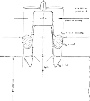
3.2 Dynamic pressure in propeller slipstream, in the figure CTP is
de-fined in equation 3.3. Abring ZWB FD 1908 (1942) reproduced from [Hoerner 1985] . . . 59
3.3 Effect of propeller slipstream on the maximum lift and the lift slope
coefficientCLα reproduced from [Hoerner 1985] . . . 60
3.4 Swirl velocity at different location after the propeller disc, reproduced
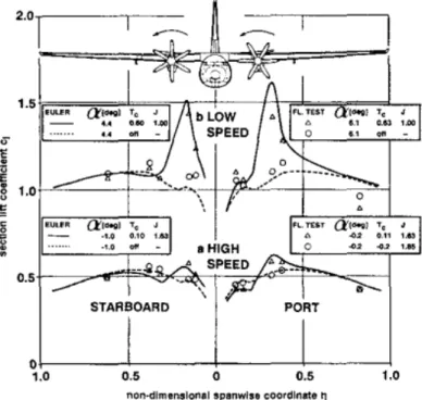
3.5 Total effect of slipstream on wing, computed and measured in flight
tests. Reproduced from [den Borne 1990]. . . 62
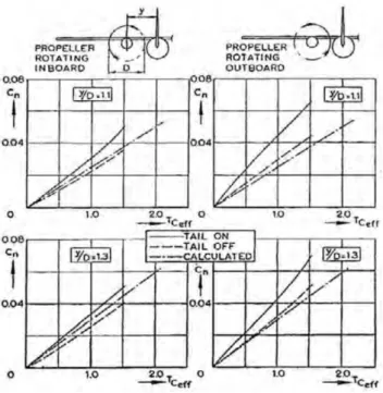
3.6 Yawing moment coefficient as a function of engine spanwise position.
TCeff in the figure is the thrust coefficient using the forward force
instead of propeller thrust. Reproduced from [Obert 2009] . . . 63
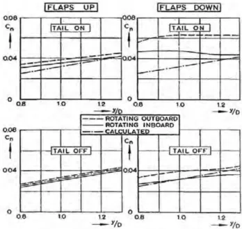
3.7 Yawing moment coefficient as a function of engine spanwise position,
effects of flap. Reproduced from [Obert 2009] . . . 64
3.8 Patterson circulation formulation (reproduced from [Patterson 2016]). 71
3.9 Illustration of the Patterson method for the treatment of differential
thrust. . . 74
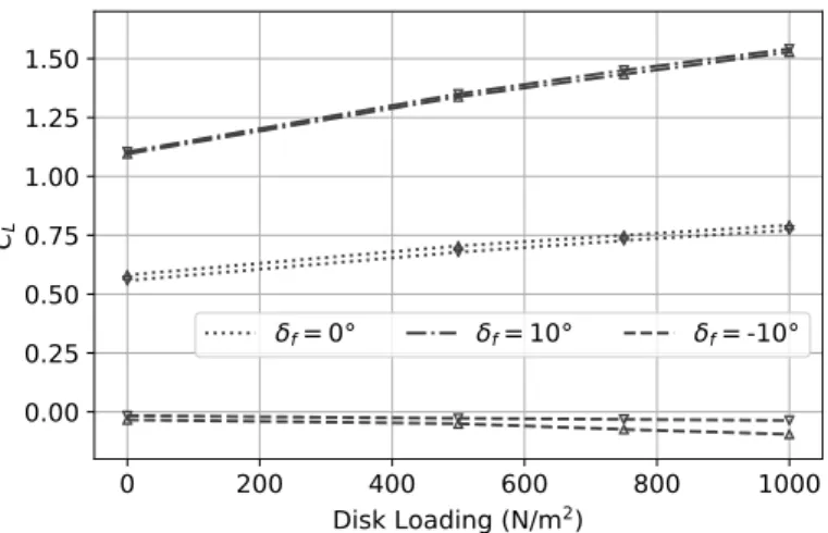
3.10 Illustration of the modifications caused by a flap deflection. . . 75
3.11 Lift increase for different flap deflection. Up triangles : VLM. Down
triangles : Patterson . . . 76
3.12 Illustration of propeller up/downwash and the contribution of the lift
force to thrust or drag. . . 78
3.13 Comparison of the extended Patterson method against the TND4448 experimental data. Coefficients include thrust and are rendered non-dimensional with respect to free stream velocity. Markers: wind
tun-nel data, lines: extended Patterson model. . . 82
3.14 Effect of propeller spacing on the lift distribution for α = 25◦ . . . . 83
3.15 Effect of propeller spacing on the downwash angleαi = wi/V
distri-bution for α = 25◦ . . . 83
3.16 Lift versus drag in black with propeller spacing 0.035Dp and in red
with propeller spacing0.1Dp. . . 84
3.17 Comparison of the extended Patterson model against TND-1586 ex-perimental data. Markers: wind tunnel data, lines: extended
Patter-son model. . . 85
3.18 Comparison of predicted flight path angles with different models and compared with flight data point collected with DECOL. The dashed
line isy = x. Flight 1. . . 89
3.19 Comparison of predicted flight path angles with different models and compared with flight data point collected with DECOL. The dashed
line isy = x. Flight 2. . . 90
4.1 Flight envelope of the original twin-engine ATR72 with simple
List of Figures xi
4.2 Original twin-engine ATR72 with interaction, climb gradient reduced
to 0%. . . 99
4.3 Twin engine ATR72Va− γa flight envelope map, without interaction. 101 4.4 Twin engine ATR72Va− γa flight envelope map, with interaction. . 103
4.5 Engine efficiencies on the twin-engine ATR72. . . 104
4.6 Engine efficiencies on the DEP ATR72 at 15◦ flap deflection. . . 106
4.7 Engine efficiencies on the DEP ATR72 at 7.5◦ flap deflection. . . 107
4.8 Engine efficiencies on the DEP ATR72 at different flap deflection. . 108
4.9 DEP ATR72Va− γa flight envelope maps with increasing number of motor failures. . . 111
4.10 Evolution of flight envelope maps with increasing number of motor failure at 3% climb gradient.. . . 114
4.11 βa− Va flight envelope of DEP with small tail Sv = 0.8Sv,0 . . . 116
5.1 Gaussian basis functions for Ng = 10 and wi = 4 . . . 126
5.2 Vertical tail mass as a function of its relative surface area . . . 127
5.3 Power distribution along the wingspan Pin(¯y) as a function of the level of failure ¯Yc. . . 131
5.4 From top to bottom: Total installed power PTin, vertical tail ratio ˜ Sv Sv0, power ratio remaining after failure P PTin. . . 132
6.1 Illustration ofH∞control and co-design. . . 143
6.2 Illustration of H∞ control and co-design on a second order model imitating the Dutch-Roll. . . 146
6.3 Bode plots of the transfer functionTβr→eβ.. . . 149
6.4 Evolution of lateral modes of the reference aircraft with the reduction of the VT surface area, from Sv/Sv0 = 1 to Sv/Sv0 = 0.1. The number in italic next to an eigenvalue indicates the corresponding Sv/Sv0. Regular numbers next to radial and circumferential dashed line refer to damping and natural frequency respectively. . . 151
6.5 Linear Fractional Representation (LFR) further simplified to M − ∆ form. . . 152
6.6 The longitudinal/lateral closed-loop control block-diagram.. . . 154
6.7 The A/C + avionics block-diagram. . . 155
6.9 Bar-diagram of the direct feed-through from reference input to
throt-tle commands.. . . 162
6.10 Aircraft poles after step 1 and step 3.. . . 162
7.1 Initial solutions allocation. . . 171
7.2 Evolution of the steady state gainC1, with motor bandwidth,ωp and
VT sizeδv. . . 172
7.3 Evolution of theH∞normC2 with motor bandwidthωpand VT size
δv. . . 172
7.4 Evolution of theH∞frequencyC3 with motor bandwidthωp and VT
size δv. . . 173
7.5 Comparison of a free and fixed allocation in variation of motor
band-width and VT surface area. . . 174
7.6 Evolution of steady state gainC1with variation of the side slip cut-off
frequency ω3. . . 175
7.7 H∞gainC2 evolution with variation of the side slip cut-off frequency
ω3. . . 175
7.8 H∞ frequency C3 evolution with variation of the side slip cut-off
frequency ω3. . . 176
7.9 Steady state gain C1 evolution with variation of airspeed and altitude.177
7.10 H∞ gainC2 evolution with variation of airspeed and altitude. . . 177
7.11 H∞ frequencyC3 evolution with variation of airspeed and altitude. . 178
7.12 Template definition forTβ˜r→ ˜dx,i(jω) . . . 181
7.13 Solution for the allocation after constrained co-design. . . 185
7.14 Aircraft poles. . . 185
7.15 Response to a βr = 15◦ doublet input. Dashed line, unsaturated
actuators, continuous line, saturated actuator. . . 186
7.16 Lateral state responses to aβr = 15◦ doublet. . . 187
7.17 Longitudinal state responses to aβr= 15◦ doublet. . . 188
8.1 Block diagram for co-design with motor failure. Feedback gainsKL, KD, Kα, Kq
are gathered under the blockK.. . . 193
8.2 Initial transfers and allocation found after multiple random starts. . 195
8.3 Evolution of the steady state gain C1 and H∞ norm C2, with motor
List of Figures xiii
8.4 Variation of the side slip cut-off frequency ω3. Aircraft with motor
failure. . . 197
8.5 Engine frequency templates for the asymmetric thrust. . . 199
8.6 Solution for the allocation after co-design. . . 201
8.7 Response to aβr= −15◦ doublet in nominal conditions. Dashed line:
with unsaturated actuators, continuous line: with saturated actuator. 202
8.8 Poles at initialisation and after co-design. . . 203
8.9 Longitudinal state responses to a βr = −15◦ doublet in asymmetric
thrust conditions. . . 204
8.10 Lateral state responses to aβr = −15◦ doublet in asymmetric thrust
conditions.. . . 205
8.11 Response to a Vr = 5 m/s step input in asymmetric conditions.
Dashed line: with unsaturated actuators, continuous line: with
satu-rated actuator. . . 206
8.12 Longitudinal state responses to a Vr = 5 m/s step in asymmetric
conditions.. . . 207
9.1 DECOL external dimensions. . . . 218
9.2 Embedded rail and nacelle positioning on the wing. . . 219
9.3 DEmonstrateur COntrol Latéral, (Lateral Control Demonstrator) (DECOL)
at the airfield. . . 220
9.4 Propeller APC thin electric 8"x6" thrust and power coefficients [Brandt 2015].222
9.5 Five-holes sphere integrated in the aircraft nose, reproduced from
[Al-Nahhas 2020]. . . 224
9.6 Aircraft lift and drag polars with increasing thrust settings. The drag
includes a zero lift term CD0 found from flight data. The stall angle
is set to11◦ for unblown case, according to [Brandt 2015]. . . 226
9.7 Lift coefficients CLα and CL0 as a function of the thrust coefficient. . 227
9.8 Coefficients of the drag polynomial equation (9.8) as a function of
thrust coefficient, calculated evolution. . . 227
9.9 Propeller forces and moment coefficients as a function of the thrust
coefficient. . . 229
9.10 Rolling and yawing moment derivatives due to an aileron deflection
as a function of Tc . . . 230
9.11 Induced rolling and yawing moment due to differential thrust at a
10.1 Example of estimation of a constant wind. First minute of the flight
including take-off.. . . 236
10.2 Calibration of multi-holes probe with flight data. . . 239
10.3 Angle of attack and acceleration factor. Herena= ka
bk−g
g . . . 239
10.4 Input sequence for lateral model identification. δe: elevator and δr:
rudder input, both in PWM.n1 andn8 : engines rotation rates, used
for differential thrust. . . 243
10.5 Evaluation of the two models for estimating the lift coefficient. . . . 245
10.6 Aircraft state during the phugoid manoeuvre associated with the lift
coefficient estimation of Fig 10.5 . . . 245
10.7 Evaluation of two models for estimating the yawing moment coefficient.251
10.8 Aircraft state during the manoeuvre associated with the yawing
mo-ment coefficient estimation in Fig 10.7. Here ∆ne is the engine
ro-tation rate differential between engine number 1 and engine number 8. . . 251
10.9 Evaluation of standard derivatives and explicit thrust derivative model
in non linear simulation, lateral side slip oscillation.. . . 254
10.10Evaluation of standard derivatives and explicit thrust derivative model
in non linear simulation, lateral Dutch Roll. . . 255
A.1 Power distribution along the wingspan as a function of the level of
failure ¯Yc. . . 269
A.2 From top to bottom: Total installed powerPT0, vertical tail ratio S˜v
Sv0,
power ratio remaining after failure PP0
T
. . . 270
B.1 Evolution of lateral modes of the reference aircraft with the reduction
of the VT surface area, from Sv/Sv0 = 1 to Sv/Sv0 = 0.1. The
number in italic next to an eigenvalue indicates the corresponding
Sv/Sv0. Regular numbers next to radial and circumferential dashed
line refer to damping and natural frequency respectively. . . 273
B.2 Evolution of the H∞ norm C2, with engine bandwidth, ωp and VT
size, δv. Red circles indicate solutions with unsatisfied constraints. . 274
C.1 Evaluation of simple model and explicit thrust derivative model in
non linear simulation, longitudinal Phugoid. . . 278
C.2 Evaluation of simple model and explicit thrust derivative model in
List of Figures xv
10.3 Illustration d’une propulsion distribuée symétriquement le long du
bord d’attaque de l’aile avecyj = −yi, j = Nm+ 1 − i. . . 283
10.4 Effet du soufflage sur la distribution de portance d’un Fokker 50
mesuré en vol à haute et faible vitesse. Reproduit à partir de [den
Borne 1990]. . . 285
10.5 Efficacités des moteurs droits (moteur n◦7 à 12). . . 287
10.6 Évolution des pôles de l’oscillation de dérapage avec la réduction de
l’empennage vertical deSv/Sv0 = 1 à Sv/Sv0 = 0.1. . . 290
10.7 Architecture des lois de commandes. . . 291
10.8 Évolution de la norme H∞ avec la bande passante moteur ωp et la
surface relative de l’empennage vertical δv.. . . 293
10.9 Gabarit fréquentiel pour les fonctions de transfert entre consignes du
pilote en latéral et les entrées moteurs. . . 294
10.10Évaluation des deux modèles pour l’estimation du coefficient de
List of Tables
1.1 Additional bounds depending on flight phase . . . 35
2.1 ATR 72 general details [Federal Aviation Administration 2015], [
Jack-son 2014], [aircraft 2000] [Lan 2005] . . . 43
2.2 Characteristics of DEP ATR 72, same as Table 2.1, except if explicitly
mentioned . . . 44
2.3 Methods for aerodynamic analysis. . . 45
2.4 A few parameters on which VeDSC has been constructed and their
interval of variation (from [Ciliberti 2013]) . . . 48
3.1 Evaluation of the number of calls to the aero-propulsive function. . . 69
3.2 Statistical analysis between the predicted and the flight measuredγa,
for data point whereγa> 0◦. . . 91
4.1 Aircraft Configurations, reference velocities are taken from the ATR’s
crew manual [aircraft 2000]. . . 98
4.2 Flight condition and configuration for theVa− γa flight envelopes of
the twin-engine ATR72. . . 102
4.3 Flight configuration and conditions for the DEP ATR72 motor
effi-ciency study. . . 105
4.4 Flight configurations and conditions for the calculation of Va− γa
flight envelope maps for the DEP aircraft with motor failures and
aero-propulsive interactions. . . 110
4.5 Flight configuration and conditions for the calculation ofβa−Vaflight
envelope maps for the DEP aircraft with interactions. . . 113
4.6 Aircraft configuration and flight condition for the calculation ofβa−
Va flight envelope for the DEP aircraft with small tail. . . 115
4.7 Reference DEP aircraft configuration and flight condition for vertical
tail sizing. . . 117
5.1 Flight Point (FP) description for the design of power distribution
6.1 H∞ control and codesign applied to a second order model of the
Dutch-Roll. . . 149
6.2 Constraintγ1and objective function values during optimization process.161 7.1 Standard configuration for sensitivity analysis.. . . 170
7.2 Difference of optimality between initialisation with eigenstructure as-signment and multiple random start. . . 170
7.3 Direct Co-design workflow . . . 183
7.4 Case study for the direct co-design application . . . 184
7.5 Co-design results . . . 184
8.1 Difference of optimality between initialisation with eigenstructure as-signment and multiple random start. . . 194
8.2 Aircraft with motor failures, trim power level. . . 198
8.3 Case study for parallel co-design . . . 199
8.4 Direct Co-design workflow . . . 200
8.5 Constraintγ1and objective function values during optimization process.201 9.1 Geometry of a 1/12 scaled model of the ATR72 using Froude scaling rules. The ATR72 is assumed to fly at 2500m and is designated by the subscript A in the table. The scaled model is supposed to fly at sea level and is designated by the subscriptm. . . 217
9.2 DECOL mass and inertia characteristics (Normal operating condition)219 10.1 Multi-hole sphere calibration parameters . . . 238
10.2 Identified lift models. Derivatives are per radians when applicable. . 244
10.3 Identified drag models. Derivatives are per radians when applicable. 246 10.4 Identified pitching moment model. Derivatives are per radians when applicable except for the control surface derivatives which are per degree. . . 247
10.5 Comparison between identified and predicted aero-propulsive lift co-efficients (see section 9.4) . . . 248
10.6 Identified models for the side force coefficient. Derivatives are per ra-dians when applicable except for the control surface derivatives which are per degree. . . 249
List of Tables xix
10.7 Identified yawing moment model. Derivatives are per radians when applicable except for the control surface derivatives which are per
degree. . . 250
10.8 Identified rolling moment model. Derivatives are per radian when applicable except for the control surface derivatives which are per
degree. . . 252
A.1 Convergence study with ¯Y = 0.5 for increasing number of basis
func-tionNg at ¯Yc= 0.5. . . 267
A.2 Convergence study with ¯Y = 0 and for increasing number of basis
function Ng at ¯Yc= 0.0. . . 267
C.1 DECOL geometry. . . 275
C.2 DECOL longitudinal stability and trim values. Note that the tilt
angles are given relative to fuselage center line. . . 276
C.3 List of measurements logged on-board the aircraft and used in
iden-tification. . . 277
10.4 Configuration de référence pour le dimensionnement de l’empennage
Acronyms
CCV Control Configured Vehicle. CFD Computation Fluid Dynamics. CG Center of Gravity.
DECOL DEmonstrateur COntrol Latéral, (Lateral Control Demonstrator). DEP Distributed Electric Propulsion.
DT Differential Thrust. DTC Direct Torque Control. ESC Electronic Speed Controller.
GNSS Global Navigation Satellite System. IMU Inertial Measurement Unit.
LFR Linear Fractional Representation. LL Lifting Line.
LMIs Linear Matrix Inequalities. MDO Multi-Disciplinary Optimization. MIMO Multiple Input Multiple Output. NED North East Down.
OEI One Engine Inoperational.
ONERA Office National d’Études et de Recherches Aérospatiales. PCA Propulsion Control Aircraft.
PIV Particle Image Velocimetry. PWM Pulse Width Modulation.
RANS Reynolds-Averaged Navier-Stokes. RC Remote Controlled.
ROS Robotic Operating System. SISO Single Input Single Output. STOL Short Take Off and Landing. UAV Unmanned Aerial Vehicle.
V/STOL Vertical/Short Take Off and Landing. VeDSC Vertical tail Design, Stability and Control. VLM Vortex Lattice Method.
Part I
0.1. Context 3
0.1
Context
The pursuit of efficient flight for transport aircraft can lead to question the rule stating that an aircraft must be statically stable. Latest civilian transport aircraft like the A380 and A350 are designed to reduced longitudinal static stability. Though requiring an automatic stability augmentation system and an emergency back-up controller, it leads to a smaller horizontal stabilizer, a reduced wetted surface area and a lower empty mass [Abzug 2005]. However, the same logic cannot be applied for the directional stability, also called weathercock stability, because theVertical Tail
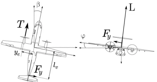
(VT) is essentially dimensioned according to the One Engine Inoperational (OEI) case illustrated by Fig1[Torenbeek 1982], [Raymer 1989], [Obert 2009]. This flight condition, requires a sufficiently large static stability or directional control power, to trim the aircraft with unbalanced thrust, sizing in turn the VT. Because this case happens at low speed, the vertical stabilizer remains oversized for the rest of the aircraft operation.
β
T
F
y
φ
L
y
e
F
y
l
v
Figure 1 – Illustration of the forces at play in equilibratedOne Engine Inoperational
(OEI) conditions.
A change of paradigm becomes possible with the emergence of new propulsion architectures and particularly theDistributed Electric Propulsion(DEP). The idea has been suggested in the literature that DEPmay unlock reduced directional sta-bility for transport aircraft [Kim 2010]. Conventional turbo-fan engine, distributed along the wingspan in pursue of the same goal, prove to be inefficient due to their inherent low reaction time [Nguyen 2018]. With the emergence of turbo-electric, hybrid and full electric propulsive systems, this idea was regarded with a new look.
The well known rapid reaction time of electric engines combined with the possibility to easily distribute electric engines, rendered this objective possible. To this day, it was not demonstrated and no methodology has been proposed to dimension an aircraft with a relaxed directional static stability and DEP.
The objectives of this dissertation are twofold:
1 - Propose a methodology for the co-design of vertical tail and control laws answer-ing the constraints of safety, flight qualities and actuator limitations.
2 - Flight demonstration of a small scale demonstrator using DEP and reduced lateral stability.
0.2. State of the art 5
0.2
State of the art
It is possible to organize the multi-disciplinary subjects related to this work under two themes: directional aircraft stability in overall aircraft design and
Dis-tributed Electric Propulsion (DEP).
0.2.1 Directional stability in overall aircraft design
On a traditional tube and wing aircraft, the function of stability is provided by the tail surfaces. Directional stability is provided by the VT, which should answer the following list of requirements [Obert 2009], [Torenbeek 1982]:
1. the VT should provide static and dynamic stability and allow control of the aircraft,
2. it should handle very large angle of side slip, up to25◦ without risk of stall,
3. it should provide a mean to trim the aircraft at all time, especially during thrust unbalance or side wind.
Requirement number 2 drives mainly the aspect ratio and sweep angle of the vertical tail. The aspect ratio is kept low and a high sweep angle of the order of 30◦ is used to avoid and delay abrupt stall. Some designs (mostly subsonic designs) include a dorsal-fin, a highly swept surface extending in front of the vertical tail having a very thin sometimes flat airfoil. This surface has the same function as the sweep angle, it does not influence the lateral side force coefficient other than delaying stall, allowing side slip angle up to 25◦ [Obert 2009]. A representation of all the elements previously described is given in Fig 2.
Rudder Dorsal fin
Vertical Tail 30°
In the literature, the definition of the VT surface area can vary. Also as a general rule for this work, the VT surface area refers to the shaded area in Fig2. Requirements 1 and 3 follow the constraints brought by aircraft certification reg-ulation. It is referred to the European certification CS25, amendment 20, subpart B, dealing with the flight requirements [EASA 2017] for large aircraft (heavier than 19 000 Lb or more than 19 passengers). CS25 contains a series of requirements that an aircraft should meet in order to demonstrate safety objectives for civilian use. Among the specification enacted for flight, paragraph CS25.147, CS25.149, CS25.177 and CS25.181 refer respectively to directional control, trim capability, static and dynamic stability. Among these criteria, the trim capability in presence of thrust unbalance is cited as the driving criterion for sizing the VT surface area in preliminary design [Torenbeek 1982], [Morris 2013], [Raymer 1989], [Nita 2008]. This limitation is measured by the minimum control airspeed Vmc which may not
be larger than 1.13Vsr whereVsr is the 1g stall velocity.
Based on the situation depicted in Fig1, an example ofVTsizing for trim objec-tive as recommended by aircraft design handbooks [Torenbeek 1982], [Raymer 1989] is proposed. In an OEIsituation, the thrustT of the remaining engine generates a yawing moment that has to be balanced by the side force Fy produced by the VT:
−Fylv+ NA−v+ T ye = 0,
where lv is the level arm between vertical tail quarter chord and aircraft Center of
Gravity (CG),NA−v is the yawing moment of the aircraft, without itsVT, at non
zero side slip andyeis the level arm between the operational engine and aircraftCG.
In this example, for a turbo-propeller aircraft equipped with an automatic feathering system, the failed engine is assumed to produce negligible additional drag1. NA−v
for aircraft with a wing of small dihedral and sweep angle, comes mainly from the fuselage in side-slip and is destabilizing.
The side force can be decomposed into the sum of forces produced by the VT in side slip,β and a deflection δR of the rudder:
Fy = 1 2ρSV 2 vCy , Cy = Cyβ((β − σv) + τrδR) ,
1. The same cannot be said for turbo-fan engines and an additional yawing moment produced by the dragging engine has to be taken into account
0.2. State of the art 7
whereCyβ is theVTside force coefficient,τr =
∂Cyβ
∂δR is the rudder efficiency factor,
S is the reference surface area, ρ is the air density, σv and Vv are respectively the
side wash angle and the airspeed at the location of theVT.
With known rudder saturation, it is possible to deduce the requiredVTsurface areaSv, or withl the reference length, a VTvolume ratio SSlvlv to trim the aircraft:
Cyβ((β − σv) + τrδR) Svlv = NA−v+ T ye 0.5ρV2 v , Svlv = NA−v+ T · ye 0.5ρV2 vCyβ((β − σv) + τrδR) .
For a twin-engine aircraft with high wing position, the propeller slipstream influences the side wash σv depending on the direction of rotation. This is the reason why
when engines are rotating in the same direction, there is one engine loss that is more critical than the other. Unless the propeller slipstream impacts directly the
VT, the term Vv is close to the airspeed at infinity.
The thrust being related to the power by the relation2: P = T V , for a constant engine power and assumingVv = V , one obtains:
Svlv = NA−v 0.5ρV2C yβ((β − σv) + τrδR) + P · ye 0.5ρV3C yβ((β − σv) + τrδR) .
The term due to the thrust unbalance being divided by V3, this relation highlights the importance of the airspeed during engine failure in the design of the VT.
In addition, the aircraft is limited by certification regulation to φ = 5◦ of bank
angle to balance the side force Fv. In preliminary design,Fv is considered to
origi-nate entirely from theVT, neglecting the fuselage contribution at this stage:
Fv = L sin φ ≈ Lφ,
from which one can express a constraint on theVTsurface area:
Sv S ≤ V2 V2 v CLφ Cyβ((β − σv) + τrδR) , with φ = 5π 180rad.
WithCyβ being fixed by requirement 2, if this constraint is violated during
prelimi-nary design, the designer has to play with the level armlv or increase the minimum
airspeed at which OEI is supposed to happen. Torenbeek [Torenbeek 1982] and
Obert [Obert 2009], argue that lateral flight handling qualities may be ignored in preliminary design, only the trim criterion inOEIshould be calculated. This is con-firmed by Nita in [Nita 2008] as an exercise to redesign a turbo-propeller transport aircraft. It is found that the trim criterion requires a larger VTthan the dynamic stability criterion. In addition, many studies [Morris 2013], [Hoerner 1985], [ Cilib-erti 2013] suggest that the VT is often over-dimensioned to cope with the difficulties of accurately predicting the VTaerodynamic performance. The flow impacting the
VT being disturbed by other aircraft components.
These are as many reasons to size the VT with a large stability margin to cope with emergency situations and low speed operations. There are however real advantages to reduce static stability on an aircraft.
0.2.2 Reduced static stability
When reducing the tail volumes i.e stability surfaces and level arms, a signifi-cant reduction in drag can be obtained thanks to the diminution of wetted surface area, trim drag and lower structural mass. In the civilian domain, this effect is in-creasingly exploited due to the important flight performance increase [Rediess 1980], [Abzug 2005].
To obtain a high level of performance improvement, the aircraft design strategy must be modified so as to include a stability and control block that can act on the geometry of the aircraft. This way, the designer can take advantage of fly by wire and active control. This discipline is called Control Configured Vehicle(CCV) and is not limited to aircraft [Abzug 2005].
An example of aircraft design based on CCV principles has been described by Anderson and Mason in [Anderson 1996]. The authors introduce the main problem withCCV; the automation of control law design and flight quality assessment in or-der to embed the discipline in aMulti-Disciplinary Optimization(MDO). They pro-pose a solution based on fuzzy logic to weight the risk associated with the complexity of the control design. This treatment is then integrated in an MDOframework for overall aircraft design.
In the following years Chudoba and Smith [Chudoba 2003] as well as Perez and Liu [Perez 2006], both presented aMDO framework with stability and control laws design based on stability augmentation system and pole placement technique. Welstead in [Welstead 2014], utilized a more advanced control design technique with the inclusion of optimal control into MDO. Recently, Denieul [Denieul 2016]
0.2. State of the art 9
realized a co-design by calculation of control law and flight control surfaces with the inclusion of flight handling quality constraints and using non smooth optimization techniques.
These examples integrate automatic control tools of increasing complexity into aircraft design. They tend toward a more global approach to handle the coupling of two or more disciplines3.
0.2.2.1 Previous attempts at VT reduction
While methods exist for designing aircraft with relaxed longitudinal stability [Cozensa 2017], reduction of directional stability remains an active field of research. Feuersanger [Feuersänger 2008] proposed a robust control design and back-up con-troller for a dynamically unstable blended wing body, with the integration of han-dling quality constraints using Linear Matrix Inequalities (LMIs) optimization. A similar approach has been used by Morris for traditional tube and wing aircraft [Morris 2013]. For both studies, the VT is reduced while ensuring satisfying han-dling qualities but the trim capability with OEI is solved by imposing a higher approach velocity.
This trim limitation can be overcome without modifying the approach velocity by increasing theVTefficiency using airflow control technology to delay flow sepa-ration on the rudder. This idea was successfully demonstrated in flight, eventually resulting in a reduction of 12% in VT surface area and 0.9% reduction in cruise drag [Mooney 2014], [Lin 2016].
Finally, there has been the idea to lower VT surface area without impacting the trim limitation using differential thrust with small turbo-fans distributed on the wing [Ameyugo 2006], [Nguyen 2018]. The authors underlined the following limitations for this idea:
— a lower engine efficiency due to small turbo-fans,
— the slow reaction time of turbo fans.
These limitations can be overcame by the consideration of a distributed electric propulsion.
0.2.3 Distributed Propulsion
Distributed propulsion without the specific mention to electric power, has a vague meaning and can designate any aircraft which propulsive system is composed of more than one engine. This definition is too broad and can lead to misconcep-tion about the original goal of power distribumisconcep-tion. NASA researcher Hyun Dae Kim proposed the following definition to refine the category of aircraft concerned by this technology: "Distributed propulsion in aircraft application is the spanwise distribution of the propulsive thrust stream such that overall vehicle benefits in terms of aerodynamic, propulsive, structural, and/or other efficiencies are mutually max-imized to enhance the vehicle mission" [Kim 2010]. DEP considered in this work falls into this definition because it is the spanwise distribution of the power that should allow an enhanced directional control with differential thrust.
Restricting the review to scientific work related toDEPwould be too restrictive in regard to the important scientific contribution in exploiting propulsion-airframe interference for Vertical/Short Take Off and Landing (V/STOL) applications.
Figure 3 – Breguet Br-941 in approach, reproduced from [Aerostories 2002]
The 1950s and 1960s saw a large interest in distributed propulsion to build
V/STOL aircraft among which the Breguet Br-941 represented in Fig 3, is worth
a presentation in the context of this work. Also known as McDonnell 188, it is rep-resentative of the blown wing concept. The Br-941 utilizes four distributed turbo-propellers to obtain high-lift characteristics, rendering possible a take-off within 140m and landing within 95m. These performances are obtained by fully embedding the wing in the propeller slipstreams. Redundancy was provided by mechanically
0.2. State of the art 11
coupling of all four propellers, making the aircraft able to maintain cruise speed with two failed power plants, without the loss of the corresponding propellers. This redun-dancy was a key aspect for the safety demonstration of the aircraft [Gambu 1959].
The most interesting detail, for this thesis is the variable-pitch propellers, which were used differentially for lateral control at low speed , [Noetinger 2001], [Quigley 1964]. Figure4, shows the propeller pitch differential applied as a function of pilot inputs.
Figure 4 – Breguet Br-941 differential propeller pitch angle as function of pilot lateral (stick) and directional (pedal) inputs, reproduced from [Quigley 1964]
DT is used both for yaw and bank pilot input. The advantages brought by
the use of DT is given by Quigley et al, as pilot’s rating of the handling quali-ties. The pilot’s rating for the lateral axis at landing goes from "satisfactory in normal operations" with DT to "unsatisfactory in normal operation" when DT is disabled. The pilot’s comments are worth a reproduction here: "The relatively large adverse yaw which occurred without differential propeller pitch was very objection-able.". Although this adverse yaw comes from the large deflected ailerons in high lift configuration,DTis said to contribute in two ways to lateral control: by increasing directional control power and by lowering adverse yaw. Interestingly, the trend is reversed during cruise and the aircraft is judged too sensitive both for the lateral and the directional axis if differential thrust is activated.
In this example, the advantages obtained with the differential use of the propul-sion systems are mostly associated with enhanced handling qualities. The impact
on the design is not clear but it may well have prevented the installation of a dis-proportionally large VT for low speed operations. The Br-941 remains the only example of differential thrust with distributed propulsion that holds an operational career (retired in 1974 [Noetinger 2001]), to the author’s knowledge.
0.2.3.1 Distributed Electric Propulsion
Propulsive architectures with specific mention of distributed electric propulsion proposed by [Drum 1924] and [Kilgore 1949], are two early examples of electrical power transmission to distributed thrust providers (see the concept of Kilgore in Fig 5).
Figure 5 – Early example of distributed electric propulsion with gasoline generators, reproduced from [Kilgore 1949].
Among the advantages, [Kilgore 1949] cites better propulsion airframe integra-tion and better propeller efficiency as the two most promising. Electric engines can be made compact enough to be buried in the airfoil and gasoline generators are installed in the fuselage, eliminating the nacelle drag. Distributing the power across many propellers allows smaller propellers with lower tip mach number and fewer blades.
If DEP is not a new idea, it gained attention in late 2010, when it became apparent that there exists a limit to the efficiency increase of turbo-fans. Whether because of airframe integration problems (example of the 737) or due to design com-plexity (geared turbo-fans), increasing the by-pass ratio to improve the propulsive efficiency is becoming more difficult [Felder 2009]. Distributing the power across many smaller electric fans appeared as an equally complex solution to increase the
0.2. State of the art 13
by-pass ratio and it offers the possibility to find synergies with the advantages of electric propulsion. In [Felder 2009], the authors provide a list of potential advan-tages for DEP. The numerous possibilities offered by DEP means that it can be employed for multiple usage. For example, it may provide high lift, redundancy and directional control as is the case for the concept plane Ampere [Liaboeuf 2018], [Dilinger 2018].
The main reason to distribute the propulsive power is to improve the propulsive efficiency [Ko 2003] or exploit beneficial aero-propulsive interactions between the propulsion and aerodynamic surfaces. Propulsion integration favoring a synergistic airframe-propulsion interaction is the source of a large amount of studies at the moment of writing [Hermetz 2016], [Schmollgruber 2019], [Clarke 2017], [Kim 2018].
0.2.3.2 Electric motors
As mentioned before, electric motors are the key systems to unlock reduced direc-tional stability thanks to their presumed fast reaction time and their good efficiency at small scale. These affirmations seem to make a general consensus in the litera-ture (see [Moore 2014] and [Hepperle 2012]), although powerful high power density electric engines of the order of 100KW to a few megawatts for aviation remain to be built and flight tested. Research efforts in this way are currently undertaken to envi-sion future electric engine technology for aircraft [Henke 2018]. Electrical engineers can rely on more than one hundred years of scientific and engineering knowledge in the domain and the work mainly resides in increasing the power density and im-proving thermal management. Examples of motors of a few hundreds KW were al-ready successfully flown in experimental test programs [Aerospace-Technology 2017], [Warwick 2019], and the E-fanX experiment promises a first test in the MW class [Airbus 2019]. The interest is not to verify these affirmations, rather to quantify the awaited performance regarding future electric motors technology for aircraft, especially concerning the bandwidth one can expect from propulsive electric motor for aircraft.
Electric V/STOL relying on vertical thrust similar to drones, are examples of flight stabilization using the principal mean of propulsion systems [Angrand 2020] and [Aviation-Week 2017]. This can be regarded as an argument in favour of active flight control with electric motors. However, vertical flight requires only small thrust variation while forward flight contains flight segment with large variation of thrust due to the more important airspeed range. The same technology may not be adapted
and a small review of electric engine drive has been found beneficial for this work. The main question remains, what kind of bandwidth can be considered for future large electric engines dedicated to aircraft propulsion?
In the example of a simple DC electric motor, the mechanical time constant is a function of electrical and mechanical construction of the motor. The torque can be controlled by varying the current through the voltage applied to the motor. With this control, the reaction time can be the order of 10−1 s [Grellet 1996]. Modern motor drives make use of power electronics and fast processors to offer digital con-trol of the engine. Among the possible methods, theDirect Torque Control(DTC) provides a response time for torque of the order of 10−3 s. Additionally, it is in-dependent of engine electrical parameters and suitable for many types of electric motor (synchronous, asynchronous) [Casadei 2006] [Zhong 1997], [Wildi 2000]. If one considers this type of control coupled with a constant speed propeller, it is clear that the limiting component for bandwidth will be the propeller pitch control actu-ator and this independently of the engine size or inertia. The bandwidth to consider can therefore be restricted to classical aeronautical actuators, of the order of 2.5Hz [Denieul 2016].
0.2.3.3 Stability reduction with distributed propulsion and DEP
The last paragraph of this literature review concerns the efforts that have al-ready been undertaken to couple stability reduction with the propulsion systems and particularly a DEP.
A special use of the propulsion system can be implemented in commercial aircraft as a back-up control system to land an aircraft that would have suffered the complete loss of hydraulic systems of the usage of the control surfaces. From a historical perspective, such a control system has been first developed by NASA and is called
Propulsion Control Aircraft (PCA), [Tucker 1999]. The loss of directional stability
following a damage caused to the vertical stabilizer can also be a reason to use the propulsion system differentially and studies have been done in this direction such as [Lu 2018]. However these researches aim at designing an emergency back-up controller and not at integrating the additional control power given by the propulsion system and the design of stability surfaces into preliminary design.
An example of the integration of the propulsion system into a longitudinal sta-bility module for multidisciplinary design can be found in [Schmollgruber 2019].
0.3. Conclusion and formulation of research paths 15
project by Empirical System [Klunk 2018b] and [Freeman 2018]. These papers report the preparation of a flight dynamic simulation environment forDEP aircraft and the set-up of a small scale demonstrator with distributed electric fans on the wing with the goal to explore a reduction of directional stability. The study by Klunk and Freeman [Klunk 2018b] focuses on the sizing criterion for the vertical tail by taking into consideration thrust reconfiguration or active control withDEP. The application case is a 150 passenger aircraft with a hybrid-electric propulsion system consisting of distributed electric fans embedded in the wing. The authors use different failure scenarios for their design and show that a trade off has to be made between directional stability at low airspeed and the mass of the electric grid for power transmission. Their conclusions being that the weight associated with an electrical grid allowing redundancy and thrust re-configuration overcomes the weight savings associated with removal of vertical tail. The potential of active differential thrust is however underlined as it may replace the vertical tail for trim requirements expressed by flight safety regulations.
0.3
Conclusion and formulation of research paths
This review was aimed at introducing the different disciplines related to the problem of relaxing the directional static stability and using an active differential thrust for flight control. The main interest seems to remain the ability to re-allocate the thrust thanks to the high redundancy and avoid thrust unbalance. The field remains largely unexplored with a high general complexity due to the number of disciplines covered and the added degrees of freedom. A first interrogation can be formulated around the sizing flight conditions for theVT. Obviously the thrust cannot be always re-allocated, there will exist a scenario of failure for which a thrust asymmetry is inevitable and one wishes to identify this critical failure condition.
The first idea to answer this problem is explored in Part II and consists of evaluating the flight envelope of the aircraft with various engine failure scenarios and variable vertical tail size. To this end, a trimming tool adapted to aircraft with distributed electric propulsion is introduced in Chapter 1 and a model to capture the variation of the vertical tail surface area is developed in Chapter2. A next work consists in improving the fidelity of the aircraft modelling and specifically in taking into account the aero-propulsive interactions, which are often cited as non-negligible forces at low speed. The principle, which is detailed in Chapter 3, is to adapt an
existing technique to the needs of the project and add it to the framework created in the previous chapters.
The unconventional aircraft configuration quickly questions the flight conditions explicitly mentioned by the certification regulation for safety demonstration, espe-cially the OEI case. Rather than considering OEI, the critical failure condition is looked for by successively switching off the engines until the trim condition can-not any more be satisfied. To overcome this iterative process, an attempt is made to invert the problem and design the propulsion system and the VT for a known critical engine failure instead of looking for the critical failure. Following these two steps, detailed in Chapter4and5respectively, the sizing flight conditions are found and general sizing rules to satisfy static trim and controllability requirements are established at the end of Part II.
In Part III, the interest will be the inclusion of the static trim requirements and the sizing flight conditions in a co-design framework where theVT, the control laws and the engine bandwidth are designed considering static trim and handling quality requirements. The main principle behind co-design is the use of optimisation tech-niques and the inclusion of both control law gains and design parameters into the set of optimisation variables. This way, it is possible for automatic control to influ-ence the design at an early phase. A known procedure to achieve this is to use H∞
control design methods and multi-objective optimisation functions. The specificity of this study will be to compute a trade-off that can answer the design constraints for both nominal and asymmetric thrust conditions with only a reconfiguration of the control gains. This part is separated in three chapters where Chapter 6 intro-duces the co-design withH∞, the control system and presents a preliminary design.
Chapter 7 explores the sensitivity of the solution to design variables allowing the definition of additional constraint and the calculation of a design trade-off. Finally Chapter8deals with the inclusion of the asymmetric thrust condition alongside the nominal flight condition in the co-design.
Knowing the limitation of the diverse models and the assumptions made for the co-design architecture, a means of validation through flight tests will be considered in Part IV. For this purpose, a DEPflight demonstrator model is built, instrumented and flight tested. The model has a 2m wingspan, weights 8.25kg and has eight engines distributed along the wing leading edge. Flight data are then used to identify a model of the aircraft that reveals the influence of the thrust on the aircraft lateral motion. This experimental work is reported in Chapter 9 for the description of the
0.3. Conclusion and formulation of research paths 17
Part II
System Modelling and Flight
Envelope Studies
Chapter 1
Flight dynamics model
Contents
1.1 Reference Frames and variables . . . 22
1.2 Variables. . . 25
1.3 Propulsion modelling . . . 28
1.3.1 Thrust and moments with DEP . . . 28
1.3.2 Propeller rotor term . . . 30
1.3.3 Propeller forces and moments . . . 31
1.4 Equations of flight . . . 32
1.5 Finding the trim position by minimisation . . . 33
1.6 Linearisation . . . 37
1.7 Conclusion . . . 38
The determination of achievable flight envelope, static and dynamic stability sup-pose the calculation of flight equilibrium or quasi-equilibrium. This can be achieved with a trim algorithm. The contours of a flight envelope can then be calculated knowing the available control power. Static and dynamic stability can be assessed after linearisation around an equilibrium point and linear control theory can be used for the design of control laws.
The starting point is therefore the construction of a trimming algorithm that can handle distributed propulsion as an actuation system and may be used in com-bination with multiple aerodynamic models. This chapter aims at constructing the mathematical model of a general DEP aircraft and a trim algorithm that can be used for a distributed architecture.
The chapter is structured as follow, a definition of the reference frames, trans-formation matrices, variables and parameters used throughout the manuscript is made in sections 1.1 and 1.2. A mathematical model of distributed propulsion is then proposed and introduced in the equations of motions in section1.3. The trim algorithm is detailed in section1.5 and the linearisation process in section1.6.
Hypothesis In order to obtain the flight dynamic equations used throughout this work, the following hypotheses are made:
1. The Earth is considered flat and fixed, 2. The wind field is considered uniform.
1.1
Reference Frames and variables
The frames presented in this section and their transformations are based on [Boiffier 1998].
The interest is to model the aircraft flight dynamics around equilibrium and/or pseudo-equilibrium for relatively short periods of time compared to a whole flight time. A convenient frame for this analysis is the aerodynamic frame, Fa, referred
with the subscripta, that allows direct monitoring of the main variables contributing
to the aerodynamic forces and propulsion. Specifically, these variables are the air velocity Va and the aerodynamic angles: βa for the slide slip and αa for the angle
of attack (see Fig 1.1).
Figure 1.1 – Body Fb and Aerodynamic Fareference frames definition.
In parallel, an experimental campaign using a flying demonstrator is planned as part of this thesis. Hence, complementary frames are defined, in which the data measured on-board the aircraft are expressed. The standard equipment observed in actual drones and that can be used to reconstruct aircraft dynamics, includes inertial and Global Navigation Satellite System (GNSS) sensors. The first delivers
1.1. Reference Frames and variables 23
measurement in body frame, Fb while the other delivers measurements in both the geocentric inertial frame FI and the vehicle carriedNorth East Down(NED) frame Fo (see Fig1.2). All three frames are taken into consideration.
ZI XI YI Zo Xo(North) Yo(East) (Down)
Figure 1.2 – Inertial Fi and local North-East-Down Fo, reference frames definition.
The transformation from the vehicle carried NED frame to the body frame is realized using the Euler angles (see Fig1.3):
— Azimuth angle ψ,
— Pitch angle θ,
— Bank angle φ.
o
Figure 1.3 – Euler angles rotation definition.
The associated rotation matrix is given as
Tob=
cos θ cos ψ sin θ sin φ cos ψ − sin ψ cos φ cos ψ sin θ cos φ + sin φ sin ψ sin ψ cos θ sin θ sin φ sin ψ + cos ψ cos φ sin θ cos φ sin ψ − sin φ cos ψ
− sin θ cos θ sin φ cos θ cos φ
The transformation from the vehicle carriedNEDFoto the aerodynamic frame Fa is realized using the aerodynamic angles:
— Aerodynamic bank angleµa,
— Aerodynamic flight path angleγa,
— Aerodynamic azimuth angleχa.
The associated rotation matrix is given as
Xo= ToaXa, (1.2) Toa=
cos χacos γa cos χasin γasin µa− sin χacos µa cos µasin γacos χa+ sin χasin µa sin χacos γa sin χasin γasin µa+ cos χacos µa cos µasin χasin γa− sin µacos χa
− sin γa cos γasin µa cos γacos µa
The transformation from the body frame Fbto the aerodynamic frame Fais realized
using the angle of attack and side slip angles:
— Angle of attackαa,
— Side slip angleβa,
The associated rotation matrix is given as
Xb= TbaXa, (1.3) Tba=
cos αacos βa − cos αasin βa − sin αa
sin βa cos βa 0
sin αacos βa − sin αasin βa cos αa
Because the previously introduced rotation matrix is orthogonal, the following prop-erty is true:
1.2. Variables 25
1.2
Variables
The variables used to model aircraft dynamics are defined here in the different reference frames when it is necessary.
The kinematic velocity of the aircraft Vk is defined in the vehicle carriedNED
frame as: Vok= uo k vo k wo k . (1.5)
Its expression in the body frame is obtained by projection:
Vb k= Tbo uo k vo k wo k . (1.6)
The air velocityVais carried in the aerodynamic frame by thexaaxis, its expression
in body frame is:
Vba= Tba Va 0 0 , Vba= ub a vb a wb a = Va cos αacos βa sin βa sin αacos βa . (1.7)
Similarly, its expression in theNEDframe is:
Vo a= Toa Va 0 0 , Vo a= uo a vo a wo a = Va cos χacos γa sin χacos γa − sin γa . (1.8)
![Figure 4 – Breguet Br-941 differential propeller pitch angle as function of pilot lateral (stick) and directional (pedal) inputs, reproduced from [Quigley 1964]](https://thumb-eu.123doks.com/thumbv2/123doknet/14675591.742360/36.892.264.640.380.672/figure-breguet-differential-propeller-function-directional-reproduced-quigley.webp)
![Table 2.4 – A few parameters on which VeDSC has been constructed and their interval of variation (from [Ciliberti 2013])](https://thumb-eu.123doks.com/thumbv2/123doknet/14675591.742360/73.892.362.725.206.582/table-parameters-vedsc-constructed-interval-variation-ciliberti.webp)
![Figure 3.3 – Effect of propeller slipstream on the maximum lift and the lift slope coefficient C L α reproduced from [Hoerner 1985]](https://thumb-eu.123doks.com/thumbv2/123doknet/14675591.742360/85.892.266.599.342.819/figure-effect-propeller-slipstream-maximum-coefficient-reproduced-hoerner.webp)