HAL Id: tel-03182754
https://tel.archives-ouvertes.fr/tel-03182754
Submitted on 26 Mar 2021
HAL is a multi-disciplinary open access
archive for the deposit and dissemination of
sci-entific research documents, whether they are
pub-lished or not. The documents may come from
teaching and research institutions in France or
abroad, or from public or private research centers.
L’archive ouverte pluridisciplinaire HAL, est
destinée au dépôt et à la diffusion de documents
scientifiques de niveau recherche, publiés ou non,
émanant des établissements d’enseignement et de
recherche français ou étrangers, des laboratoires
publics ou privés.
Study of a MagnetoElectric Transducer to Wireless
Power Medical Implants
Giulia Rizzo
To cite this version:
Giulia Rizzo. Study of a MagnetoElectric Transducer to Wireless Power Medical Implants.
Electro-magnetism. Université Paris-Saclay, 2020. English. �NNT : 2020UPAST012�. �tel-03182754�
Study of a MagnetoElectric Transducer
to Wireless Power Medical Implants
Thèse de doctorat de l'université Paris-Saclay
École doctorale n°575 Electrical, optical, bio-physics, and engineering (EOBE) Spécialité de doctorat : Electronique et Optoélectronique, Nano- et Microtechnologies
Unité de recherche : Université Paris-Saclay, CNRS, Centre de Nanosciences et de Nanotechnologies, 91120, Palaiseau, France
Référent : Faculté des sciences d’Orsay
Thèse présentée et soutenue à Paris-Saclay,
le 18/12/2020, par
Giulia RIZZO
Composition du Jury
Adrien BADEL
Professeur, Université Savoie Mont Blanc Président
Mickaël LALLART
Professeur, INSA de Lyon Rapporteur & Examinateur
Hakeim TALLEB
Maître de Conférences, HDR, Sorbonne Université Rapporteur & Examinateur
Ilangko BALASINGHAM
Professeur, Norwegian University of Science, and Technology Examinateur
Vincent LOYAU
Maître de Conférences, ENS Paris-Saclay Examinateur
Elie LEFEUVRE
Professeur, Université Paris Saclay Directeur de thèse
Jean Christophe LOURME
CEO ValoTec, and MELLISIM Co-Encadrant de thèse
ccccccccc
N
N
T
20
20
UP
AS
T01
2
3
4
Acknowledgements
Je tiens à remercier tout particulièrement les membres de mon jury Mr. Badel, Mr. Lallart, Mr. Talleb, Mr. Balasingham et Mr. Loyau, pour avoir acceptés de lire ce manuscrit et d’évaluer mon travail de thèse.
Je souhaite dire vraiment merci à mon directeur de thèse, Mr. Elie Lefeuvre, et mon co-encadrant, Mr. Lourme, pour avoir acceptés de me suivre et m’encadrer tout au long de cette thèse. Merci pour m’avoir donné la possibilité de faire partie du projet européen WIBEC, pour tous les trainings suivis et aussi pour toutes les conférences auxquelles j’ai pu assister.
Thank you to all the WiBEC team for the incredible journey that was this ITN. I could not have imagined a better PhD program. I had the possibility to join the groups of Ovesco Endoscopy AG, MicroPort CRM and Oslo University Hospital during the secondments, and meet new colleagues. Thank you for these amazing experiences.
Merci aux collègues du C2N pour m’avoir accueillie dans leur équipe pendant les trois années de thèses. Merci pour toute la connaissance transmise, les aides, les pauses café ensemble, les moments partagés. Merci à tous les professeurs, les post-docs et les doctorants. Merci surtout à Alexiane pour la précieuse amitié née à un tournois de baby-foot et qui restera pour l’avenir.
Également je remercie le groupe de ValoTec, avec une mention spéciale pour Thomas pour tous les moments partagés à VTC et dehors, avec et sans café, en face d’un oscilloscope ou derrière son écran pc.
Un grazie speciale a Maria Luisa, Maria José e Chloé che ci sono sempre. Grazie agli amici di Parigi, del 2Bis, gli amici di Torino, di Houston, del Vietnam, di Mirandola, di Grenoble. Un grazie enorme, perchè non sarebbe stato lo stesso senza di voi !
Infine, ultimo ma assolutamente non ultimo, vorrei ringraziare la mia famiglia che mi è sempre stata accanto e permesso di fare questo percorso. Grazie per i vostri insegnamenti, i vostri valori e la vostra fiducia. Grazie ai miei genitori, a mio fratello e a Piera.
5
Résumé en français
De nos jours, les dispositifs médicaux actifs implantables jouent un rôle important dans la surveillance, le diagnostic et le traitement des patients, grâce à des fonctionnalités de plus en plus étendues. Au cours des dernières décennies, l’accent a été mis sur le développement de dispositifs implantables plus durables et moins invasifs. Ces deux aspects sont directement liés aux sources d'énergie utilisées pour alimenter les implants. En fait, dans un dispositif implantable, la majeure partie du volume disponible n'est pas occupée par l'électronique qui gère ses fonctions, mais par la batterie qui l'alimente. Le volume occupé par la batterie est assez directement lié à la durée de vie de l’appareil, avec toutefois une limite liée au phénomène d’auto-décharge. Pour certains types d'implants à long terme tels que les stimulateurs cardiaques, il est nécessaire de remplacer l’implant déchargé au moyen de procédures chirurgicales coûteuses et invasives. Aujourd'hui, deux approches ont été développées, afin d'éviter les batteries à usage unique et les inconvénients associés. La première approche consiste à récupérer l'énergie présente à l'intérieur du corps, disponible au niveau de l'implant, et la deuxième consiste à transmettre l'énergie depuis l'extérieur du corps humain. Dans le premier cas, par exemple, il est possible d'alimenter un stimulateur cardiaque de nouvelle génération en convertissent l'énergie mécanique provenant des battements cardiaques, grâce à un MEMS piézoélectrique. Dans le second cas, la télé-alimentation utilisant le phénomène d’induction magnétique entre deux bobines (l'une implantée, l'autre à l’extérieur du corps) est une technologie de plus en plus répandue dans le domaine biomédical, comme pour la recharge d'un téléphone portable sans contact dans la vie de tous les jours. La principale différence entre ces deux approches est le niveau de puissance qui peut être obtenu : les MEMS de récupération d'énergie mécanique peuvent fournir des microwatts d'énergie électrique, tandis que la transmission d'énergie sans fil implique des puissances allant du milliwatt au watt.
Cette thèse porte sur l’étude d’un système de télé-alimentation. En général, cette technologie permet d'alimenter les dispositifs médicaux implantables grâce aux interactions magnétiques entre une bobine émettrice externe et une bobine réceptrice implantée dans le corps. L’originalité de l’approche développée dans cette thèse consiste à utiliser un transducteur magnétoélectrique (ME) à la place de la bobine réceptrice. Ce transducteur magnétoélectrique est un dispositif hybride, formé de deux matériaux liés mécaniquement, l’un magnétostrictif et l’autre piézoélectrique. Le matériau magnétostrictif présente un couplage entre les grandeurs magnétiques et mécaniques. Il est capable de se déformer élastiquement sous l’effet d’un champ magnétique. Cette propriété est réversible, et elle est liée à un changement de son aimantation interne. Le matériau piézoélectrique assure un couplage entre les grandeurs mécaniques et électriques. Soumis à une contrainte mécanique, sa déformation élastique opère une conversion d’énergie mécanique en énergie électrique (effet piézoélectrique direct). Cette propriété est également réversible (effet piézoélectrique inverse). Par conséquent, le dispositif ME considéré assure le couplage entre les grandeurs électriques et magnétiques par l’intermédiaire une déformation mécanique. Le transducteur magnétoélectrique assure ainsi la conversion d'énergie du domaine magnétique et au domaine électrique et vice versa. Dans l’application considérée, le champ magnétique est généré par la bobine émettrice externe. Il en résulte une déformation élastique du transducteur qui permet de générer de l’électricité. Cette énergie électrique peut ensuite être extraite et utilisée pour recharger ou alimenter le dispositif implanté. Comparativement à une bobine réceptrice classique, le
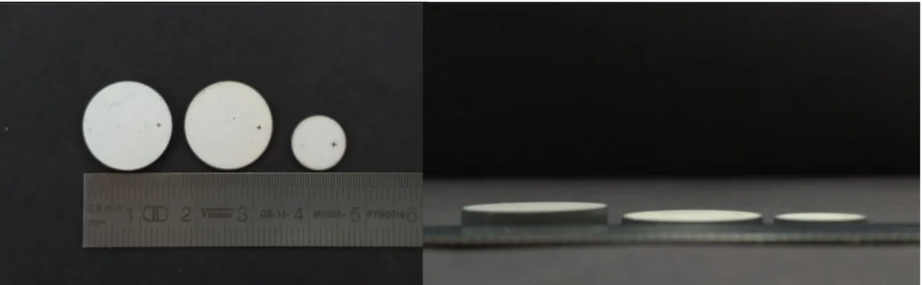
Figure 0.1 –Photo de composites magnétoélectriques de 16 mm de diamètre et d'épaisseurs différentes étudiés au cours
6
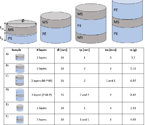
transducteur ME pourrait permettre de réduire la dépendance de l’efficacité du système de transmission d’énergie à un bon alignement entre l’émetteur et le récepteur. Cet aspect est très important dans le domaine des implants médicaux actifs, dont la localisation et l’orientation sont parfois difficiles à connaître précisément et à suivre en temps réel, notamment pour les implants connectés à des organes ou des muscles. Dans ce but, un transducteur magnétoélectrique a été développé en se basant sur les propriétés magnétostrictives et piézoélectriques de matériaux disponibles commercialement. Plusieurs échantillons ont été fabriqués et caractérisés dans le but de quantifier expérimentalement la relation entre les dimensions, la composition et l’efficacité du composite en termes de transduction d’énergie. La littérature du domaine, peu abondante, présente quelques exemples de transducteur ME, notamment sous la forme d’empilements de plaques rectangulaires. Dans cette thèse, la forme de disque a été choisie pour favoriser la pénétration du champ magnétique dans le transducteur. Deux diamètres de 10 mm et 16 mm ont été retenus (Figure 0.1). Plusieurs configurations et compositions de matériaux ont été étudiées, avec une épaisseur totale comprise entre 2 mm et 5 mm.
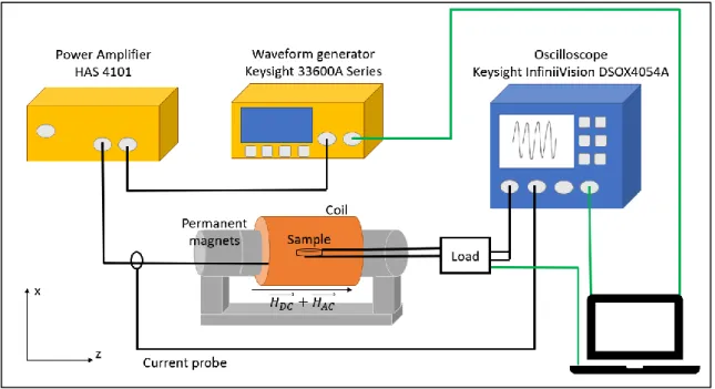
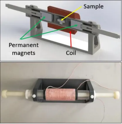
Un dispositif de test, assez éloigné d’une configuration implantée, a été réalisé dans le but d’étudier l’influence respective des composantes continue et alternative du champ magnétique appliqué sur l’échantillon sur la tension et la puissance électrique générée. Dans ce dispositif, le champ magnétique continu est généré par une paire d'aimants permanents, tandis que le champ magnétique alternatif est généré à l’aide d’une bobine placée autour de l'échantillon (Figure 0.2).
Ce travail de caractérisation a permis d’identifier la gamme de fréquences optimale, c’est-à-dire celle dans laquelle on bénéficie d’un mode de résonance favorable du transducteur. Les échantillons de grand diamètre (16 mm) permettent d’atteindre une puissance de sortie de 40 mW (Figure 0.3) dans les conditions optimales de champ continu et dans les conditions maximales de champ alternatif que le banc de test permet de générer. Les tendances observées tendent à montrer que les échantillons les plus épais, avec une fraction volumique de matériau magnétostrictif plus faible, délivrent une puissance électrique inférieure (de l’ordre de 30%) et ont une densité de puissance plus faible que celle des échantillons les plus mince, avec une fraction volumique de matériau magnétostrictif plus élevée. Ainsi, un échantillon de 16 mm de diamètre et de 5 mm d’épaisseur contenant 20% de matériau magnétostrictif délivre une puissance inférieure à celle d’un échantillon de 10 mm de diamètre et de 2 mm d’épaisseur contenant 50% de matériau magnétostrictif (respectivement PMP-20% et MP-50%, Figure 0.3). L’ensemble des résultats obtenus ouvre des perspectives intéressantes de miniaturisation du transducteur ME tout en conservant une bonne efficacité de transfert d’énergie sans fil.
Figure 0.2 – Mise en place de tests de caractérisation. Sur la photo du haut, le porte-échantillon est représenté. La photo de droite montre le banc de test.
7
Les résultats expérimentaux ont également été utilisés pour identifier les paramètres d’un modèle théorique linéaire permettant de reproduire le comportement du transducteur ME. Il s’agit d’un modèle assez classique, basé sur celui d’un résonateur piézoélectrique (modèle de Mason) auquel est ajouté un terme de couplage magnétostrictif. Les phénomènes couplés entre la partie magnétostrictive et la couche piézoélectrique du transducteur sont représentés par trois blocs principaux, reliés par deux coefficients de couplage. Le premier coefficient, ϕm, traduit le couplage magnéto-mécanique provenant du matériau magnétostrictif ; le deuxième,
ϕp, représente l’effet élasto-électrique du matériau piézoélectrique (Figure 4.9).
Afin de déterminer les paramètres du modèle, une première mesure de tous les dispositifs a été réalisée en régime statique (champ magnétique continu uniquement). L'impédance du dispositif magnétoélectrique a été mesurée sous différents champs magnétiques DC. A partir de ce premier test, il a été possible de quantifier l'influence du champ DC sur la fréquence de résonance du système et sur les paramètres de rigidité mécanique et d'amortissement. Une deuxième série de mesures a été réalisée en régime dynamique, en appliquant un champ magnétique alternatif et un champ DC, et en mesurant la tension de sortie en condition de circuit ouvert. À partir de ces deux séries de mesures, il est théoriquement possible de prédire le comportement des dispositifs ME, comme par exemple déterminer la puissance de sortie sur une charge résistive.
Figure 0.4 – Schéma du modèle de circuit équivalent pour transducteur magnétoélectrique. En vert pour le bloc magnétique, en rouge pour la partie mécanique et en bleu pour l'électrique. Graphique de droite : coefficient magnétoélectrique déterminé expérimentalement pour différentes valeurs du champ DC.
Figure 0.3 – Courbes de gauche : puissance en fonction de la fréquence pour différentes charges résistives connectées à l’échantillon. Les courbes colorés représentent les valeurs expérimentales, la courbe noire correspond à la puissance maximale donnée par modèle théorique linéaire. Le graphique de droite représente les valeurs maximales de densité de puissance de quatre échantillons différents.
8
La méthode d’identification permet de déterminer l’ensemble des paramètres à partir d'une mesure expérimentale. Les puissances calculées à l’aide du modèle présentent un écart de l’ordre de 10% par rapport aux mesures expérimentales, ce qui est acceptable. Il pourrait être amélioré en tenant compte des non-linéarités, notamment celles qui proviennent du matériau magnétostrictif. La prise en compte de l’échauffement induit par les courants de Foucault et de l’effet de la température sur le comportement du système serait un prolongement intéressant.
De manière à s’approcher davantage de l'application visée, dans laquelle le transducteur magnétoélectrique étudié contribue à alimenter un dispositif médical implantable par la charge de sa batterie interne, un circuit redresseur a été ajouté dans le dispositif étudié. En effet, le transducteur magnétoélectrique génère une tension alternative qu’il convient de redresser pour recharger la batterie. Un circuit redresseur en pont complet et un circuit redresseur en demi-pont ont été successivement ajoutés au circuit. L’ensemble des caractérisations a été répété avec l’ensemble des échantillons et le modèle théorique a été modifié pour intégrer cette partie du circuit. Le transducteur ME associé à un redresseur conduit à une puissance de sortie plus faible que sans redresseur (34 mW au maximum, contre 40 mW), ce qui s’explique en partie par les pertes dues aux diodes. Les puissances obtenues avec les deux types de redresseur sont assez similaires, la tension de sortie du demi-pont étant pratiquement deux fois plus importante que celle du pont complet. Les pertes dues aux diodes sont plus faibles en raison de leur nombre déduit dans le circuit en demi-pont et de la tension plus élevée du transducteur. Du point de vue du modèle, l’écart se situe toujours aux alentours de 10% par rapport aux valeurs expérimentales.
Une partie du travail expérimental est axé sur la comparaison qualitative de l'efficacité du transfert de puissance d'un système de bobine-ME et d'un système de bobine-bobine, sous différentes orientations relatives de l’émetteur et du récepteur. L'objectif était de recréer les conditions pratiques d’incertitude de positionnement relatif du bloc émetteur hors corps et du bloc récepteur interne. Les échantillons ont été successivement fixés sur le bras d’un un robot mécanique à 5 degrés de liberté, permettant de déplacer l’échantillon avec précision selon différentes orientations et distances de l'émetteur. Pour cette expérience, le dispositif émetteur de champ magnétique utilisé est composé d’une bobine sur ferrite et de deux aimants permanents. La configuration originale de cet émetteur de champs continu et alternatif présente l’intérêt d’être assez efficace et utilisable dans le cas d’un implant (Figure 2.11).
9
Trois récepteurs différents ont été comparés : une bobine sans noyau, une bobine avec noyau de ferrite et un transducteur ME de mêmes dimensions. Le récepteur ME présente l’avantage de produire de l'énergie électrique dans toutes les orientations par rapport à l’émetteur. Le matériau magnétostrictif présente un axe préférentiel de magnétisation le long duquel le transducteur ME est le plus efficace. Cependant, l’expérience montre que l’on atteint un niveau de tension de sortie (et donc de puissance) exploitable même en dehors de l’alignement optimal. Par exemple, on mesure 1,5 V en sortie du récepteur à 30 mm de distance de l’émetteur dans la condition de pire alignement, alors que la tension des bobines réceptrices est nulle dans le cas du pire alignement. Le transducteur ME permet donc d'avoir une transmission de puissance non-nulle quelle que soient la position et l'orientation relative entre le bloc externe et L’implant. Rappelons qu’il s’agit d’un aspect important pour l’application visée, la position des implants étant très difficile à suivre en temps réel, en particulier pour les dispositifs connectés à des organes ou des muscles. L’intérêt de la configuration particulière de l’émetteur a été confirmée dans le cadre d’une expérience réalisée dans un milieu constitué de viande animale. Ces tests ont permis de vérifier la répétabilité des mesures précédemment réalisées avec le robot sous différentes orientations du récepteur. La viande de canard a été choisie pour la conformation des tissus adipeux à l'intérieur de la viande. Les résultats obtenus sont très encourageants, aussi bien au niveau de l’émetteur que du récepteur, et ouvrent d’intéressantes perspectives pour la télé-alimentation (ou télé-recharge) de dispositifs implantables.
En conclusion, cette thèse rapporte des résultats prometteurs concernant l'utilisation de transducteurs magnétoélectriques pour le transfert d'énergie sans fil pour la recharge et l’alimentation de dispositifs médicaux implantables. L’approche expérimentale développée permet de tirer des conclusions générales concernant l’effet de la composition du transducteur sur ses performances. Cependant, aller vers un transducteur ME optimisé nécessiterai de développer un modèle multiphysique à éléments finis en tenant compte des propriétés physiques réelles des matériaux, et en particularité des non-linéarités du matériau magnétostrictif. Un tel modèle permettrait également de rendre compte de l’échauffement induit par les courants de Foucault et d’éventuelles contraintes thermomécaniques influant sur les propriétés et performances du composite ME. Un tel modèle s’avère nécessaire pour déterminer la composition et les dimensions optimales du transducteur dans des conditions de fonctionnement données. Comme indiqué précédemment, les résultats expérimentaux obtenus ouvrent la perspective de miniaturiser le transducteur ME sans perdre en efficacité ni en densité de puissance. Dans cette perspective, il serait intéressant d’étudier le potentiel de nano-composites ME. De tels développements permettraient d’aller vers des transducteurs magnétoélectriques intégrés, compact et performants adaptés aux contraintes des dispositifs médicaux implantables. Des matériaux à magnétostriction géante autres que le Terfenol-D utilisé au cours de cette thèse, tels que le Galfenol et le MetGlas sont disponibles sur le marché. Il serait intéressant d'explorer les avantages et les limites de la transduction ME en utilisant et en associant ces matériaux par rapport aux résultats de cette thèse et de la littérature. Des ferrites à base de Ni-Zn-Co qui présentent des coefficients de magnétostriction géants pourraient également constituer une alternative intéressante. Enfin, la possibilité d’utiliser un matériau magnétostrictif auto-polarisé, qui ne nécessitant pas de champ magnétique continu, permettrait de simplifier la mise en œuvre de ce mode de transduction dans le contexte d’applications biomédicales.
Figure 0.6 – Résultats de tests in-vitro. Le graphique à gauche représente le système bobine-bobine en position parallèle et le graphique de droite le système bobine-transducteur magnétoélectrique en position parallèle, pour différents hauteurs (z) et décalage horizontales (x).
10
Les perspectives de poursuite de ce travail sont donc multiples, du point de vue des matériaux, de la fabrication des composites, de la miniaturisation et des modèles multiphysiques. De tels approfondissements permettraient d’aboutir à des solutions performantes ultra compactes pour la transmission d’énergie et la télé-alimentation de dispositifs médicaux implantables.
Cette thèse a été financée par le programme de formation du réseau de formation innovant Marie Skłodowska-Curie Actions de l’Union européenne pour le projet ‘Wireless In-Body Environment Communication – (WiBEC)’ dans le cadre de la convention de subvention n. 675353
11
Contextual foreword
This Ph.D. was carried out from the 19th of June 2017 to the 18th of December 2020 (date of the defense) in the
Île-de-France region of France.
The Ph.D. was performed between the enterprise ValoTec and the Center for Nanoscience and Nanotechnology (C2N) of the Université Paris-Saclay.
ValoTec stems from Ecole Normale Supérieure de Paris-Saclay (SATIE laboratory), as an enterprise, specialized in their R&D and production projects since 2005. The domain of expertise in technology development is related to active innovative devices (all industries), class IIa IIb and III medical devices (medical technologies), implantable devices, patient treatment devices, and diagnostic devices.
The Université Paris-Saclay is a research university conglomerate exiting in various locations of the Île-de-France region including the Saclay plateau near Palaiseau, south-west of Paris. Initially, this Ph.D. was (jointly) performed at the C2N laboratory of the Université Paris-Sud, near Orsay. It was not until late 2018, however, that the laboratory was moved to the Saclay plateau once Université Sud was absorbed by Université Paris-Saclay.
The Ph.D. also formed part of the European Commission-funded Innovative Training Network ‘WiBEC’ (Wireless In-Body Environment Communication) consisting of several academic, clinical, and industrial members located throughout Europe. Various training courses (technical and non-technical/horizontal), presentations, and conferences were carried out at all of these member institutions throughout the Ph.D. Several brief secondments were also performed within this context, two-months secondment at Ovesco Endoscopy AG, in Tubingen, Germany, two-months secondment at MicroPort CRM in Clamart, France, and one-month secondment in the University Hospital of Oslo in Oslo, Norway.
13
Contents
Acknowledgements ... 4
Résumé en français ... 5
Contextual foreword ... 11
List of Abbreviation ... 16
Chapter 1 Active Implantable Medical Devices and their energy sources ... 17
1.
Introduction ... 19
2.
Implantable Medical Device ... 20
3.
Active Implantable Medical Devices ... 21
3.1
Physiological Function ... 21
3.1.1
Cardiovascular devices ... 22
3.1.2
Gastroenterology devices ... 23
3.1.3
Neural devices ... 24
3.2
Packaging Materials ... 25
3.2.1
Metals ... 27
3.2.2
Ceramics, and Composites ... 27
3.2.3
Polymers... 28
3.3
Power Consumption ... 28
3.4
Energy sources ... 29
3.4.1
Battery ... 29
3.4.2
Wireless Power Transmission ... 30
3.4.3
Energy Harvester ... 32
4.
Medical Regulatory ... 35
5.
Conclusion ... 38
6.
Bibliography ... 40
7.
List of figures ... 42
8.
List of tables ... 43
Chapter 2 Model and Application of a MagnetoElectric transducer ... 45
1.
Introduction ... 47
2.
Magnetic Materials ... 48
2.1
Principles, and structures ... 49
2.2
Fundamental Equations ... 51
2.3
Magnetostriction ... 54
2.3.1
Piezomagnetism ... 55
14
2.4
Applications ... 57
3.
Piezoelectric Materials ... 59
3.1
Principles, and Structures ... 60
3.2
Fundamental Equations ... 62
3.3
Oscillation modes/Dynamic Behavior ... 63
3.4
Type of piezoelectric materials ... 65
3.5
Applications ... 66
4.
MagnetoElectric Composites ... 68
4.1
Principles, and structures ... 69
4.2
Fundamental Equations ... 71
4.2.1
Magnetostrictive Constitutive Equations ... 72
4.2.2
Piezoelectric Constitutive Equations ... 72
4.2.3
MagnetoElectric Constitutive Equations... 73
4.3
Equivalent circuit model ... 74
4.3.1
Static Regime... 76
4.3.2
Dynamic Regime ... 78
4.3.3
Output Power, and Optimal Electrical Load... 79
4.3.4
Model with Rectifier ... 80
4.4
Considered Materials ... 82
4.4.1
Magnetostrictive material ... 82
4.4.2
Piezoelectric material ... 84
4.4.3
Description of the MagnetoElectric Samples ... 85
4.4.4
FEM analysis of radial resonance modes ... 86
4.5
Application ... 88
5.
Conclusion ... 90
6.
Bibliography ... 91
7.
List of figures ... 94
8.
List of tables ... 95
Chapter 3 Experimental measurements of a MagnetoElectric transducer ... 97
1.
Introduction ... 99
2.
Characterization test ... 100
2.1
Measurement Set up ... 100
2.2
Circuit Model ... 103
2.2.1
Static regime ... 103
2.2.2
Dynamic regime ... 108
2.2.3
Output power ... 111
15
2.3
MagnetoElectric Samples... 115
2.4
Characterization Method ... 116
2.5
Results, and Discussion ... 119
3.
Medical Regulatory Compatibility... 131
4.
In-vitro Test ... 132
4.1
Measurement Set up ... 133
4.2
Tested Samples ... 134
4.3
Method... 136
4.4
Results, and Discussion ... 137
5.
Phantom Test ... 144
5.1
Measurement Set up ... 144
5.2
Tested Samples ... 145
5.3
Method... 146
5.4
Results, and Discussion ... 147
6.
Conclusion ... 149
7.
Bibliography ... 151
8.
List of figures ... 152
9.
List of tables ... 155
Chapter 4 Conclusion ... 157
1.
Conclusion ... 159
2.
Bibliography ... 161
Appendix I ... 163
Appendix II ... 165
Appendix III ... 168
Abstracts ... 205
16
List of Abbreviation
AIMD – Active Implantable Medical Device BMI – Brain Machine Interface
CRT - Cardiac Resynchronization Therapy D.U.T. – Device Under Test
EMF – Electro Magnetic Field GI - Gastro-Intestinal
ICD - Implantable Cardioverter - Defibrillators IMD – Implantable Medical Device
LCP – Leadless Cardiac Pacemaker LED – Light Emitting Diode
LVAD – Left Ventricular Assist Device ME – MagnetoElectric
MERAM - Magnetoelectric random access memories MS – Magnetostrictive material
NIR – Near-Infrared Region OC – Open Circuit
PE – Piezoelectric material PZT – Lead ZirconateTitanium RF – Radio Frequency
SAR – Specific Absorption Rate WCE – Wireless Capsule Endoscope
17
Chapter 1
Active Implantable Medical Devices and
their energy sources
18
Table of Contents
Chapter 1 Active Implantable Medical Devices and their energy sources ... 17
1.
Introduction ... 19
2.
Implantable Medical Device ... 20
3.
Active Implantable Medical Devices ... 21
3.1
Physiological Function ... 21
3.1.1
Cardiovascular devices ... 22
3.1.2
Gastroenterology devices ... 23
3.1.3
Neural devices ... 24
3.2
Packaging Materials ... 25
3.2.1
Metals ... 27
3.2.2
Ceramics, and Composites ... 27
3.2.3
Polymers... 28
3.3
Power Consumption ... 28
3.4
Energy sources ... 29
3.4.1
Battery ... 29
3.4.2
Wireless Power Transmission ... 30
3.4.3
Energy Harvester ... 32
4.
Medical Regulatory ... 35
5.
Conclusion ... 38
6.
Bibliography ... 40
7.
List of figures ... 42
8.
List of tables ... 43
19
1. Introduction
The first chapter of this thesis gives a general view of the context of implantable medical devices. Nowadays, the market of medical systems is very wide, heterogeneous, and in continuous evolution. Figure 1.1 shows the trend of the European medical devices market in the last, and next years. These systems are almost able to monitor the human physiological responses, diagnose pain, and issues, and treat medicine; all these functions to afford a better quality of life for the patient.
For the interest of this thesis, specific attention on the active implantable medical devices is reported. The focus of this analysis consisted of the study of medical implants from four points of view: physiological applications, packaging materials, power consumption, and energy sources. The physiological applications analyze the medical device’s functionalities inside the patient’s body, the part of packaging explores the main used materials to encapsulate the implants, the power consumption, and energy sources are linked to the working conditions of the system. Each aspect contributes to producing a complete, reliable, and safe medical device for the patient’s use.
A main investigation of the most employed energy sources is conducted, to understand the advantages and disadvantages of the actual technologies. From this basis, the study of a MagnetoElectric transducer from the perspective of developing compact, and efficient wireless power transmission systems will be introduced.
20
2. Implantable Medical Device
Every year, millions of patients improve their quality of life through surgical procedures that involve implanted medical devices. Jiang and Zhou [2] have described that at least 8% to 10% of the population of all Americas (20 million to 25 million people), and about 1 over 17 people in industrialized countries have experienced a medical implant for rebuilding body functions, achieving a better quality of life, or expanding longevity.
In general, the term implant is used for devices that replace a missing or support a damaged biological structure. In specific, a medical device is defined as implantable, if it is either partly or totally introduced, surgically or medically, into the human body or natural orifice, and it is intended to remain there after the procedure [3][4]. Nowadays, advances in microfabrication, and bio/chemical engineering technology are enabling a large variety of miniaturized implantable systems for diagnosing, healthy monitoring, treatment, and injury compensation. This trend of progress in medical implants will continue for the coming super-aged society, which will result in more consumers of these devices, especially for one or more diseases: estimates show that 90% of the population over the age of 40 suffers from some degree of degenerative joint disease [5].
The IMD technologies are continuously assisted, and supervised by the regulatory authorities, like the Food, and Drug Administration (FDA), and the European Commission (CE). They can control the device production, and to guarantee patient safety. In general, the medical regulatory recognizes different classes of medical devices, based on their design complexity, their usage, and their potential of risk, if misused.
Each country or region defines these categories in different ways. When some devices are provided with drugs, the combination of them will be controlled by the regulation. The FDA and CE classification of medical devices is based upon the level of control required to ensure the safety, and effectiveness of the device. The classification procedures are described in the Code of Federal Regulations, Title 21, part 860 (usually known as 21 CFR 860).
21
Class I devices are subject to the least regulatory control “general controls”. Class I devices are not intended
for use in supporting or sustaining life or to be of substantial importance in preventing impairment to human health, and they may not present a potential unreasonable risk of illness or injury. Examples of Class I devices include elastic bandages, examination gloves, and hand-held surgical instruments.
Class II devices are those for which general controls alone are insufficient to ensure safety, and effectiveness
for the patient and existing methods are available to provide such insurances. In addition to complying with general controls, Class II devices are also subjected to special controls. A few class II devices are exempt from the premarket notification. Special controls may include special labeling requirements, mandatory performance standards, and post-market surveillance. Examples of class II devices include powered wheelchairs, infusion pumps, and surgical drapes.
Class III device is one for which insufficient information exists to ensure safety and effectiveness. Such a
device needs premarket approval, a scientific review to ensure the device’s safety, and effectiveness, in addition to the general controls of Class I, and II. Class III devices are usually those that support or sustain human life and are of substantial importance in preventing impairment of human health or those which present a potential, unreasonable risk of illness or injury. Examples of class III devices include implantable pacemaker, pulse generators, HIV diagnostic tests, automated external defibrillators, and osseous implants. The devices discussed in this chapter belong to class III. These implants mostly find their applications in the orthopedic, neural, gastroenterology, and cardiovascular fields as well as soft tissue implants such as implants used in plastic surgery.
Over this general review, the medical implantable systems can be further classified into two macro groups, active (mostly class II, and III), and passive (class I, and II). The IMDs that do not need power are termed as passive devices, e.g. artificial joints, vascular grafts, and dental implants. On the contrary, the active IMDs depend on a source of energy, which can be directly generated by the human body or by external phenomena/system, e.g. cardiac pacemaker, cochlear implants, and insulin pumps. This thesis will be focused on the Active Implantable Medical Devices.
3. Active Implantable Medical Devices
Over the last six decades, numerous engineering, and medical activities for Active Implantable Medical Device (AIMD) development have faced challenges in functionality, electrical consumption, packaging materials, wireless communications, and power supply. Since the first pacemaker implant in 1958, this progress is driving physicians, and patients to express an increasing desire for miniaturized implantable devices, as they are offering less invasive implantation procedures, greater comfort for the patient, improved performances, and often provide innovative measurements, and treatments [5].
Since the market of the Implantable Medical Devices is very wide, and heterogeneous, this chapter will analyze the AIMDs from the point of view of four main aspects: physiological function, power consumption, packaging materials, and energy sources.
3.1 Physiological Function
The design of an active implantable system typically comprises two blocks, an indwelling module which resides inside the patient, and an external device located outside the body with which the implant communicates, and/or is powered. Within the host body, the electrical system can reside intracavity, e.g. within intestinal systems, or be subcutaneously or deeply implanted [7]. In the following paragraphs three AIMDs, one for each type of implantation, will be described on the base of the most common patients’ disorders, and WIBEC’s project applications:
- Cardiac Pacemaker (long-term deep implant) - Capsule Endoscope (temporary intracavity implant) - Neural stimulator (long-term subcutaneous implant).
22
3.1.1 Cardiovascular devices
Cardiovascular diseases are the leading causes of mortality in the Western World, and responsible for 37.5% of all deaths in the EU [9]. Disturbance of cardiac rhythm and malfunction of the heart’s conduction system is the result of disease processes such as hypertension or coronary artery-, and valvular- heart disease. Cardiac rhythm management devices are developed to maintain, improve, or restore heart rhythm [10]. They are mainly divided into three classes:
1. Anti-bradycardia (heart rate is abnormally slow, fewer than 60 beats per minute) or tachycardia- (heart rate is abnormally fast, more than 100 beats per minute) - pacemakers
2. Implantable cardioverter-defibrillators (ICD) 3. Cardiac resynchronization therapy devices (CRT).
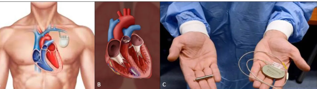
In general, implanted cardiac rhythm management devices consist of a subcutaneous metallic can, containing the control unit, and the energy source. The can is connected to single, double, or multiple leads with electrodes at the tips, which detect cardiac activity, and stimulate the myocardium to contract when required [9]. The control unit communicates with the external programmer during follow-up visits, to obtain stored or real-time records of cardiac, and pacing activities. Modern implanted cardiac devices have at least three functions: sensing electric pulses of the heart through one or more electrical leads, processing the information by the control unit, and pacing or defibrillation action, through the leads [9]. An implanted cardiac pacemaker is represented in Figure 3.1A.
Since the development of the first implantable pacemaker in 1958, pacing technology has dramatically improved. Size has been reduced, the battery lasts longer (until 10 years), sensors and algorithms are smarter, and surgical methods are safer. However, the components of the leads remain the “weak point” of the system, with issues such as infection, venous occlusion, high risk-extraction [8]. One of the solutions is to merge the can, and the lead into one single device, the leadless cardiac pacemaker (LCP). Leadless cardiac pacemaker (Figure 3.1B) shall be the miniaturized all-in-one self-contained cardiac pacing device that must sense, process the signals, communicate with physicians, and pace.
LCP is a long-term deep implant, which consists of a power generator, sensors, current injector, and an integrated battery unit. The concept was proposed 40 years ago, but only recently became a clinical reality [9]. Two commercial systems are already available on the market: MicraTM (Medtronic Inc., Minneapolis, USA), and
NanostimTM (St. Jude Medical Inc., Minneapolis, USA). Neither MicraTM and NanostimTM have a permanent power
solution, making battery replacement a technical challenge. This limitation may potentially be overcome by new sources of energy (paragraph 3.4).
Furthermore, the new challenge studied in the context of the WIBEC project and addressed to different cardiac diseases consists of using multiple LCPs; one LCP in each of the major myocardium chambers, to have control over the entire heart. The challenge consists of obtaining a complete synchronization between all the cardiac implants, and the external recorder, through different techniques such as Human Body Communications [11] or Radio Frequency Communications [12].
Figure 3.1 – Figure A) represents an implanted cardiac pacemaker. Figure B) represents a leadless cardiac pacemaker. Figure 2C shows the different sizes of leadless pacemaker (in the left hand), and an old-generation pacemaker (in the right hand) [39].
23
3.1.2 Gastroenterology devices
Among digestive diseases, colorectal cancer has the highest mortality rates worldwide [13]. At present, the primary tool for gastrointestinal screening is the flexible endoscope. Unfortunately, it is accompanied by a non-negligible risk of trauma, breach, and sometimes infections. To overpass these issues, a Wireless Capsule Endoscope (WCE) emerged in the 21st century as a painless, and non-invasive diagnostic IMD. Wireless Capsule
Endoscope is a temporary intracavity AIMD, able to explore the Gastro-Intestinal (GI) tract by wirelessly transmitting images from a disposable capsule to a data recorder (Figure 3.2).
The WCE system consists of 3 blocks: a capsule endoscope, sensing, and data record system, and a computer for image review, and interpretation. All capsule endoscopes have similar components: a disposable plastic capsule, a CMOS or high-resolution image capture system, a compact lens, white-light-emitting diode illumination sources, and an internal battery source [15].
The first capsule model for the small bowel was approved by the FDA in 2001 [15]. Nowadays in the market, there are different products as PillCam (Medtronic Inc., Minneapolis, USA), EndoCapsule (Olympus America, Inc., Center Valley, USA), and MiroCam (IntroMedic Co Ltd, Seoul, Korea).
The mode of transmission data can be either via ultra-high RF (PillCam, EndoCapsule) or human body communications (MiroCam). In Table 3.1 all three products are compared, based on the data of [15]. The new challenges addressed to this innovative device and explored in the context of the WIBEC project, aim to externally control the WCE and to automatically recognize the polyps during the image processing. The first challenge consists of magnetic control of the capsule stabilization, and locomotion, to address it to a specific area if needed [16]. The second one is based on automatic detection in frames of CE videos, through machine learning techniques, to detect risky regions in the small bowel, before proceeding with biopsy [17].
Table 3.1 – Comparison between WCE systems.
WCE Company Size (mm) Weight (g) Image/s Battery life Resolution (pixels)
EndoCapsule, Olympus America 11 x 26 3.5 2 8 hours 512 x 512 PillCam, Medtronic 11 x 26 2.8 2 12 hours 256 x 256 MiroCam, IntroMedic Co Ltd 11 x 24 3.3 3 11 hours 320 x 320 A
B
Figure 3.2 – Figure 3A represents the scheme of a Wireless Capsule Endoscope. Figure 3B represents the endoscopy process, with a pain-less Wireless Capsule Endoscope [14].
24
3.1.3 Neural devices
Neurological disorders such as epilepsy, multiple sclerosis, Parkinson’s disease affects the central, and peripheral nervous system, e.g. the brain, spinal cord, peripheral nerves. Recent neural interfaces have shown great potential in the diagnosis, and prediction of neurological events. In fact, Brain Machine Interface (BMI) can simultaneously record, and elaborate neurophysiological signals from large numbers of single neurons, across a wide range of spatial, and temporal scales. Most current recording systems require a wired percutaneous connection between the electrodes and external recording units.
In the market, there are already some examples of neurorecording, and stimulator implantable systems, e.g. RestoreSensorTM (Medtronic Inc., Minneapolis, USA). The 16-electrode medical system is a long-term implant,
supplied by a rechargeable battery, which consists of three parts: neurostimulator, leads, and patient’s programmer. The implantable device delivers mild electrical signals to the epidural space near the spinal cord through leads.
Unfortunately, the wired percutaneous connections severely restrict the subject’s mobility, present possible brain infection, and cause potential contamination of the signals, due to the external noise/interference. The new challenge, proposed by the research community, and in particular by Yin M. et al [18], presents a wireless neural recording device system (Figure 3.3). The AIMD integrates 100 wideband neural recording channels and a GHz wireless telemetry module for data transfer.
The implant is a long-term device, hermetically sealed in a titanium enclosure, and subcutaneously located over the skull [18]. The neural sensing is performed by a 100-electrode intracortical array (Blackrock Microsystem MEA [19]). The system is powered by a medical grade 200 mAh rechargeable Li-ion battery, charged by inductive coupling. Wireless powering through induction is one of the possible solutions to the finite-lifetime of the common battery. This technology found a wide range of activities for AIMD, making them less invasive, and theoretically infinite lifetime (paragraph 33.4.1).
Figure 3.3 – Photographs (on the left), and scheme (on the right) of the 100-Ch fully implantable wireless neurosensing device [18].
25
3.2 Packaging Materials
In general, the choice of packaging is mostly influenced by the expected lifetime of the device, to guarantee its hermeticity, and its biocompatibility with the interactive tissues, organs, and blood. The elasticity, yield strength, ductility, fatigue strength, and hardness are some of the important mechanical evaluated properties of materials. For example, the yield strength determines the load-bearing capability of the implant; the elastic modulus measures the resistance to the elastic deformation, when stress is applied, or the tensile strength measures the ability to withstand loads tending to elongate. All these aspects have been evaluated during the choice of the implants’ encapsulation. Furthermore, an estimation of the device’s hermeticity has been done. All materials leak, or more accurately, all materials are permeable to some gas to some degree. Welds and joints between materials may have pre-existing cracks or pores that provide a leakage path. The total "leak" is thus a combination of both the bulk permeation through the material and any open leak paths that lead directly from the internal to the external environment. Therefore, the process of ensuring hermeticity can be described as the selection of materials, and manufacturing techniques that yield an enclosure that has sufficient material thickness to impede the diffusion of gas into the internal package cavity, and that can be sealed without pinholes, cracks, or other discontinuities that provide a direct leak path. The following figure can give, an index of the permeability of different materials (Figure 3.4).
Therefore, the device failure can be induced either by the effect of the materials/device’s package, but also by the host environment. In 1987, Williams defined biocompatibility as “the ability of a material to perform with an appropriate host response in a specific application” [21]. Biocompatibility is not a single event or a single phenomenon, but it involves different mechanisms of interaction between materials, and tissues. Furthermore, no material is unequivocally biocompatible; it may be biocompatible under one or more specific conditions but cannot be assumed to display biocompatibility under all conditions [22].
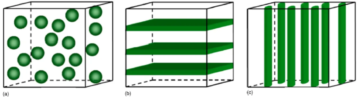
The research community is investigating new biomaterials, to tailor, and control the biological reaction to an IMDs. With the development of new biomaterials, a new branch of science came out: Biomaterials science. This term refers to the physical, and biological study of materials, and their interactions with the biological environment. It includes the synthesis, optimization, characterization, and testing of host-material interactions. In general, most of the materials used for AIMDs can be divided into three categories: metals, ceramics, and polymers. Metals are formed by metallic bonds, and include pure metals, and alloys; ceramics are principally based on ionic bonds and include glasses, glass-ceramics, and carbons. On the contrary, polymers are made by covalent bonds and include thermosets, thermoplastics, elastomers, and textiles. In the following (Figure 3.5), they are compared from a mechanical point of view. As biomaterial is very vast and complex, just some materials will be analyzed in the following paragraphs, on the base of the studied implants.
26
27
3.2.1 Metals
As a class of materials, metals are the most widely used for load-bearing implants. In general, they are chosen for the high corrosion rates, and good biocompatibility, ideal to guarantee long-term devices’ hermeticity. Metals are employed either in passive IMDs, for example for orthopaedic applications as artificial joints or fracture fixation plates, but also in active IMDs, for example for cardiovascular devices as pacemakers’ case or ventricular assist devices. The mainly used metals are stainless steels, cobalt-base alloys, and pure titanium/titanium alloys.
Stainless steels are iron-base alloys, which achieve very high corrosion rates, and the ability of self-healing, once damaged, thanks to the formation of an invisible, and adherent chromium-rich oxide surface film [23]. Based on the characteristic crystallographic structure/microstructures of the alloys, stainless steels are classified into four classes: martensitic, ferritic, austenitic, and duplex. In the following chapter, the ferritic materials will be further explained and used for transducer fabrication (Chapter 2, Paragraph 2.4.4.3).
Cobalt-chromium alloys are highly corrosion resistant. Compared to stainless steel, they exhibit higher elastic modulus, strength, and hardness, but they have relatively low ductility and are difficult to machine. They possess adequate fatigue properties to serve as artificial joints or total joint prostheses and are used extensively for this purpose [23].
Commercially pure titanium is well known for its excellent corrosion resistance, and excellent grade of biocompatibility. Various percentages of unalloyed titanium are available with oxygen, and iron as primary variants. Biomedical applications for commercially pure titanium grades include pacemaker cases, enclosure for ventricular assist devices, and neuronal stimulators [23].
In the following (Table 3.2), the 3 classes of metals are compared on the base of their characteristics, and mechanical properties.
Stainless steels Cobalt-base alloys Ti, and Ti-base alloys
Principal element Fe Co Ti
Variants Ni, Cr, Mo Ni, Mo, Cr Al, Nb, V Young’s modulus (GPa) 200 230 110 Tensil strength (MPa) 540 – 1000 900 – 1540 950 Advantages Cost, availability,
manufacture
Wear resistance, corrosion rate, fatigue strength
Biocompatibility, corrosion rate, minimum modulus, fatigue strength
Disadvantages Long-term behavior, high modulus
High modulus, biocompatibility
Lower wear resistance, low shear strength Applications Temporary devices as
fracture plates, screws, hip replacements.
Orthopaedic prostheses, total joint replacements, dentistry casting.
Long-term devices as modular femoral heads, cardiovascular devices.
Table 3.2 - Comparison of characteristics, and mechanical properties of metallic implants materials [21].
3.2.2 Ceramics, and Composites
Ceramics, glasses, and glass-ceramics have been essential for a long time in the medical industry for repair or replacement of musculoskeletal hard connective tissues, such as the bone, and dental implants. They are generally chosen for the high stability in the attachment, and good insulation to heating, and electricity. The bone itself is a composite, comprising an organic phase, and a ceramic phase, which is predominantly calcium hydroxyapatite with a Ca/P ratio of 1.67.
Thus, synthetic calcium hydroxyapatite is a good candidate for a successful biomaterial. Several dental and orthopaedic metal implants are coated with it to ensure long-term fixation in bones [23]. The poor fracture toughness and low plasticity of ceramics severely limit their employment for load-bearing applications. A specific ceramic that is used in load-bearing applications is high-density, and high-purity alumina (Al2O3). It is used in
load-bearing hip prostheses, and dental implants, for its combination of excellent corrosion resistance, good biocompatibility, high wear resistance, and high strength [21].
28
On the contrary, certain compositions of glasses, and glass-ceramics are specialized in soft tissue bonding and defined as bioactive glasses. A common characteristic of bioactive ceramics is a time-dependent, kinetic modification of the surface that occurs on implantation. The surface forms a biologically active adherent layer, that provides the bonding interface with tissues, and resists substantial mechanical forces [21].
For this thesis, the ceramic materials will be further investigated in the paragraph (Chapter 2, Paragraph 2.4.4.2).
3.2.3 Polymers
Polymeric materials are rapidly replacing for biomedical uses other material classes, such as metals alloys, and ceramics, for their versatility, especially for temporary device. Their application is very wide, in the following (Table 3.3) there are some examples with the respective employments in implantable medical devices.
Polymers Applications
Poly (ether urethane urea) Artificial heart components, heart valve Low, and high-density polyethylene Tubing, knee, hip, shoulder joints Polysulfones Artificial heart components, heart valve Polypropylene Heart valve structures
Parylene Endoscopic capsule Polyesters Drug delivery system Polyamides (nylons) Hemodialysis membrane
Table 3.3 – Examples of polymers, and their applications in IMDs [23].
Polymeric materials are generally classified into three different classes, depending on their origin: natural polymers, obtained from natural sources, including animals, and plants; synthetic polymers, and bio-inspired polymers, which comprise materials synthesized to mimic a naturally occurring polymer [23]. Natural polymers suffer from various disadvantages, such as the possibility of antigenicity, and microbial contamination. Hence, synthetic (and bio-inspired) polymers are preferred for implants application, for the easy production, availability, and versatility of manipulation [23].
3.3 Power Consumption
In the past few decades, tremendous developments in electronics, micro-, and nanofabrication, and wireless technology have greatly enhanced the quality, and efficacy of healthcare as well as life-science research. Nowadays, the AIMDs are used for diagnosis, monitoring, and treatment, but to ensure proper operations they need to rely on permanent, and sufficient power supply. Before analyzing the different powering technologies, it is necessary to understand the range of power consumption of the most common AIMDs. It is possible to classify them into three groups: W-consumption, as the Left Ventricular Assist Device (LVAD), mW-consumption, as the neural stimulator, and µW-consumption, as the cardiac pacemaker, (see Table 3.4).
Device Device functionalities Power consumption
LVAD Mechanical pumping the heart blood 5 - 15 W Leadless Pacemaker Cardiac rhythm management 1 – 10 µW ICD Cardiac rhythm management 40 – 60 µW Vagus nerve stimulation Delivering electrical impulses to the vagus nerve 60 – 70 µW Implantable drug pump Delivering medication through the spinal cord/body 1 mW Cochlear implant Electrical stimulation of the cochlear nerve 10 mW Neurostimulator Electrical brain stimulation 100 mW Wireless Capsule Endoscope Wireless exploration of Gastro-Intestinal tract 500 mW
Table 3.4 - Typical implants power requirements [25].
From these power requirements, numerous energy sources for AIMDs have been widely investigated in the last decades, respecting the main constraints of size limitations, device’s localization (deep/subcutaneous implant), source’s continuity, and biocompatibility.
29
3.4 Energy sources
Since the late 1950s, most of the implantable medical electronic devices such as cardiac pacemakers, vagus nerve stimulators, and deep brain stimulators, have been powered by batteries [26]. However, the use of batteries imposes several limitations to the current AIMDs. Firstly, due to the finite lifetime of batteries, surgeries are often required to replace the discharged units. Secondly, while electronic circuits get smaller dimensions with the rapid development of semiconductor integrated circuit (IC) technologies, the batteries’ volumetric capacity has improved rather slowly in the past few decades [27]. Thirdly, the battery has an impact also in the weight of the implantable system, which becomes a major hurdle in minimizing the overall device’s size. In addition, even though AIMD are tightly sealed with biocompatible encapsulation materials, there is a risk for electrolytes leakage from the battery, which may cause toxic effects and inflammatory reaction in tissues [27]. For these reasons, researchers have been developing fully implantable microsystems without batteries as internal power sources and exploring various types of wireless powering methods.
In many cases, external power transmitters deliver energy in the form of radiofrequency (RF) waves, ultrasound, or light, and implantable microsystems receive the energy through specific energy harvesting components or antennas. Additionally, there are cases where implantable microsystems are directly equipped with energy harvesters to capture energy from the biological environment [27]. In general, when power is transferred to implanted microsystems through biological tissues, many factors must be considered such as transmission depth, amount of necessary energy, exposition to movements-mechanical stress. The tissues have multi-layer structures with relatively high scattering, and absorption characteristics, which can result in high energy losses, low transfer efficiency, and at the same time highly damage risk, due to heating, and energy absorption.
In the following paragraphs, three types of power supply systems will be described: battery, wireless power transmission, and energy harvesting.
3.4.1 Battery
The first battery was invented by Volta in 1796, and since then numerous types have been discovered and applied to different uses in human life. In general, batteries store energy in the form of chemical substances, which can produce electricity. Batteries contain anodes, cathodes, and electrolytes to allow ions to move thus forming currents. Power capabilities of batteries can have different performances (low rate, medium rate, and high rate) on the base of the AIMD functionalities [25]. Figure 3.6 shows some examples of implantable medical devices powered by batteries, and their lifetimes.
The most employed battery is Li-based, where Li metal anodes are associated with ion-cathode systems, such as iodine (Li/I2), manganese oxide (Li/MnO2), or carbon monofluoride (Li/CFx). As reliable sources for long-term
applications such as cochlear implants, pacemakers, cardiac defibrillators, or drug delivery, these Li batteries have been widely employed to provide appropriate power levels ranging from µA to A [25]. Among those, Li/I2
batteries have been proved to be safer, and more reliable than others for implantable devices. Li/I2 batteries
30
have a discharge voltage of up to 3.6 V, which is equal to three times the voltage generated by Ni-based cells. Their energy density can reach 210 Wh/kg, which can power a cardiac pacemaker for several years [5].
Another alternative, more durable, could be the nuclear battery, in which power is transformed into electricity through energy carried by particles emitted from radioisotopes. This process could be produced by the particles, emitted from the radioisotopes, or coming from the ionization of emitted particle bundles, or the photoelectrical conversion prompted by a fluorescent material [25]. The advantages of nuclear batteries lie in providing much longer service life (>15 years) than all other competitors, and their output energy is extremely stable, regardless of environmental factors (temperature, pressure, and electric field).
Furthermore, their safety has been proved for as long as they are kept hermetic, however, the potential radioactivity danger, as well as their expensive cost, make them still unacceptable [25].
3.4.2 Wireless Power Transmission
Wireless Power Transmission is a technology, which allows transferring a high amount of energy with the constant availability of the energy source. The three major wireless powering transfers are based on radio-frequency (RF) electromagnetic waves (working radio-frequency 103 – 109 Hz), ultrasound (1 – 10 MHz), and infrared
light (100 THz) (see scheme on Figure 3.7).
RF Electromagnetic Wave Transmission
Delivery energy through RF electromagnetic waves has been widely used in many areas of electrical engineering, especially for powering biomedical implants. The electromagnetic energy can be transferred by inductive coupling through two coils or antennas, with a range of frequency comprised between kHz to GHz. The first case is typical of a near-field electromagnetic interaction, the second one is related to a far-field transfer.
Figure 3.7 – Schematic transcutaneous wireless energy transfer concept: an external device transmits power to the implantable device through RF waves, infrared light, and ultrasounds [5].
31
For the near-field technique, the power transfer method consists of using a slowly changing magnetic field, created by the primary coil, to generate an electromotive force, and electric power at the secondary coil (see Figure 3.8). The requirements to have an efficient transmission are linked to the resonance frequency, distance, alignment, coupling, and size of coils. Therefore, implantable microsystems using inductive coupling are usually designed to deliver a large amount of energy to a receiver with a large coil, located within a short distance [27].
In the precedent paragraph 13.1.3, a neural stimulator, inductively powered, has been described. The inductive wireless power transmission was used, in that case, to recharge a 200 mAh Li-ion battery at 150 kHz.
On the contrary, the RF radiative energy transfer, also called a far-field transfer, uses antennas with resonance frequencies usually higher than those used in inductive coupling (high RF waves up to GHz).
Transmission, between antennas in the far-field area, may provide energy to multiple microsystems at different depths, and do not require accurate alignment. However, this technology shows relatively lower power transmission efficiency, because the radiative power density decreases rapidly at the far-field region; in general, RF attenuation in a human body is larger at higher frequencies [27]. Additionally, it exposes the tissues to a high risk of damage, and heating. An example of this energy transmission is explained by Montgomery KL. et al [28], who reports the development of an implantable wireless neural device, RF powered, which controls the behavior of mice throughout the nervous system (brain, spinal, and peripheral nerve endings).
Ultrasound Wave Transmission
The ultrasound wave is a mechanical wave with oscillating frequencies higher than the upper limit of the human hearing; typical frequencies in the range of [3 – 6] MHz, acoustic velocities in body tissues about 1500 – 2000 m/s, and wavelengths of 0.3 – 0.7 mm [29]. This phenomenon is already employed in the biomedical field for medical imaging, and therapy [30]. Regarding the energy transfer, it consists of an external mechanical source, as a piezoelectric material, which generates the ultrasound waves. The last ones propagate inside the body and arrive at a piezoelectric harvester, which converts it into electric power.
Since the acoustic wavelength results shorter than the RF one at the same frequency, the ultrasounds show a higher transfer efficiency, and penetration depth than the radiative transmission, especially for large separation between source, and receiver [29]. The conversion rate between the ultrasonic transmitter and received power is estimated at 80%, which brings the ultrasound waves more effective than the conventional RF energy transfer [31]. For example, Tsai JY. et al [32], presented a neural stimulator, which uses ultrasounds in the MHz-range for power, and data transmission. At an acoustic power of 112 mW from the transmit transducer, 4.15 mW can be received, and made available by the device, which only consumes a power of 1,8 mW for neural stimulation.
Unlikely, the disadvantage of this technology is mostly linked to the low ultrasound transmittance in the bones, especially for the skull, due to the impedance mismatch between the bone, and the other media, and the tissue heating, due to the mechanical vibration at high frequencies [29]. This problem is noticed also in the infrared light energy transmission.
![Figure 3.9 – Working principle of the optical WPT system as intended for a cardiac pacemaker, and other IMDs [33]](https://thumb-eu.123doks.com/thumbv2/123doknet/14545783.725344/33.892.188.661.515.735/figure-working-principle-optical-intended-cardiac-pacemaker-imds.webp)
![Figure 2.4 – Curves of first magnetization, a) for a DC field, and b) for an AC field [1]](https://thumb-eu.123doks.com/thumbv2/123doknet/14545783.725344/54.892.171.724.547.787/figure-curves-magnetization-dc-field-b-ac-field.webp)
![Figure 2.6 – Hysteresis loop as function of the anisotropy, K1, and the internal deformation ơλ s [13]](https://thumb-eu.123doks.com/thumbv2/123doknet/14545783.725344/56.892.187.685.412.680/figure-hysteresis-loop-function-anisotropy-internal-deformation-ơλ.webp)
![Figure 4.10 – Scheme of a transducer energy harvester. A) Physical point of view. B) Electrical point of view [42]](https://thumb-eu.123doks.com/thumbv2/123doknet/14545783.725344/76.892.99.767.111.329/figure-scheme-transducer-energy-harvester-physical-point-electrical.webp)