HAL Id: tel-00952026
https://tel.archives-ouvertes.fr/tel-00952026
Submitted on 26 Feb 2014HAL is a multi-disciplinary open access archive for the deposit and dissemination of sci-entific research documents, whether they are pub-lished or not. The documents may come from teaching and research institutions in France or abroad, or from public or private research centers.
L’archive ouverte pluridisciplinaire HAL, est destinée au dépôt et à la diffusion de documents scientifiques de niveau recherche, publiés ou non, émanant des établissements d’enseignement et de recherche français ou étrangers, des laboratoires publics ou privés.
Modification chimique de la cellulose nanofibrillée par
les alcoxysilanes : application à l’élaboration de
composites et mousses
Zheng Zhang
To cite this version:
Zheng Zhang. Modification chimique de la cellulose nanofibrillée par les alcoxysilanes : application à l’élaboration de composites et mousses. Other. Université Sciences et Technologies - Bordeaux I, 2013. English. �NNT : 2013BOR14888�. �tel-00952026�
N° d'ordre : 4888
THESE
présentée àL'UNIVERSITÉ BORDEAUX 1
ÉCOLE DOCTORALE DES SCIENCES CHIMIQUESpar
ZHENG ZHANG
POUR OBTENIR LE GRADE DEDOCTEUR
SPÉCIALITÉ: POLYMÈRES
CHEMICAL FUNCTIONALIZATION OF NANOFIBRILLATED
CELLULOSE BY ALKOXYSILANES: APPLICATION TO THE
ELABORATION OF COMPOSITES AND FOAMS
Soutenue le 12 Novembre 2013
Après avis de :
MM. N. Belgacem, Professeur, INP-Pagora, Grenoble Rapporteur P. Navard, Directeur de recherche, CEMEF, Nice Rapporteur
Devant la commission d'examen formée de:
MM. B. De Jéso, Professeur, Université Bordeaux, Bordeaux Président N. Belgacem, Professeur, INP-Pagora, Grenoble Rapporteur P. Navard, Directeur de recherche, CEMEF, Nice Rapporteur T. Zimmermann, Dr., EMPA, Dübendorf Examinateur P. Tingaut, Dr., EMPA, Dübendorf Examinateur G. Sèbe, Maître de Conférences, Université Bordeaux, Bordeaux Examinateur
-Acknowledgements
I wish to express my most sincere gratitude to my supervisors, Dr. Gilles Sèbe of University Bordeaux and Dr. Philippe Tingaut of EMPA. Dr Gilles Sèbe gave me the most valuable advice, to guide me on the right way. Despite the distance between Bordeaux and Zurich, the communication with Dr. Sèbe and his feedbacks were always very fast, which I really appreciated. Dr. Philippe Tingaut has spent countless time and work in this project, and I deeply thank him for the discussions, helps, suggestions and feedbacks at any time. He was not only a great supervisor, but also a good colleague during my entire PhD study.
I would also like to express my special gratitude to our head of the lab, Dr. Tanja Zimmermann, who has greatly supported me, helped me during some difficult periods and shared her experience with me, as an experienced scientist, as well as a friend.
This work would not be possible without helps from many people and my few words of gratefulness could not be compared with the help and support these people gave me. I would like to thank my great and supportive colleagues, Margrit Conradin, Esther Strub, Dr. Houssine Sehaqui, Paola Orsolini, Franziska Grüneberger, Uxua Pérez de Larraya, Dr. Sebastien Josset, Anja Huch, Robert Widmann, Robert Jockwer and my students Julia Weiss, Vincent and Christoph. Many other people of the institute have also contributed very important parts to this book: Beatrice Fischer, Dr. Daniel Rentsch, Marcel Rees and Dr. James Eilertsen.
In the end, I wish to avail myself of this opportunity, to express a sense of appreciation and love to my mother and my deceased father for their unconditional love and support. Last but not least, my beloved husband deserves my most heartily thanks for his support, encouragement and understanding.
Ce travail de thèse s’inscrit dans le cadre d’un projet financé par la Commission pour la Technologie et l’Innovation (CTI) Suisse (projet « SICEPO », contrat CTI N° 9725.1) visant à développer une méthode de silylation de la Cellulose Nanofibrillée (CNF) en milieu aqueux afin d’améliorer ses propriétés intrinsèques et étendre son champs d’applications. Ce projet a été réalisé au Swiss Federal Laboratories for Materials Science and Technology (EMPA, Dübendorf, Suisse) en collaboration avec le Laboratoire de Chimie des Polymères Organiques (LCPO, Université de Bordeaux, France) et deux partenaires industriels : Falcone Chemical Specialities Ltd. (Siebnen, Suisse) et Jelu-Werk Josef Ehrler GmbH & Co. KG (Rosenberg, Allemagne).
Au cours de ce travail, la cellulose nanofibrillée (CNF) a été isolée à partir de fibres de paille d’avoine puis modifiée chimiquement par des alcoxysilanes en milieu aqueux. La CNF silylée a ensuite été utilisée pour élaborer de nouveaux matériaux composites et mousses bio-sourcés.
Après une introduction générale situant le contexte de cette thèse, une première partie bibliographique (Chapitre I) présente la composition chimique des plantes, les différentes mé-thodes de synthèse des nanocelluloses, et décrit les propriétés principales de la CNF (Figure 1) ainsi que ses applications dans le domaine des composites, aérogels et mousses. La CNF présentant certains inconvénients liés à sa structure chimique (en particulier son caractère hy-drophile), un état de l’art des différentes approches de fonctionnalisation chimique permettant de limiter ses inconvénients est présenté. Au regard de cette étude bibliographique, il apparaît que la majorité des méthodes de modification chimique envisagées jusqu’à présent nécessitent des conditions anhydres et l’utilisation de solvants organiques. Il existe cependant une mé-thode à base d’alcoxysilanes, permettant de fonctionnaliser les substrats hydroxylés en milieu aqueux et dans des conditions douces. Cette méthode de silylation ayant été très peu appliquée à la CNF, il nous est apparu nécessaire de poursuivre et amplifier les recherches dans ce do-maine, afin de mieux caractériser le matériau silylé et de bien maîtriser le procédé.
Figure 1 Photomicrographie de NFC isolée à partir de paille d’avoine, utilisée lors de
ce travail de thèse.
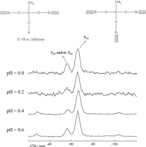
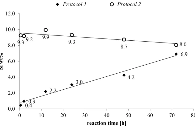
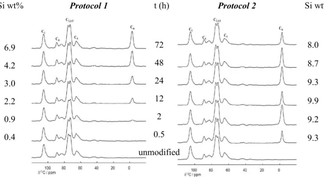
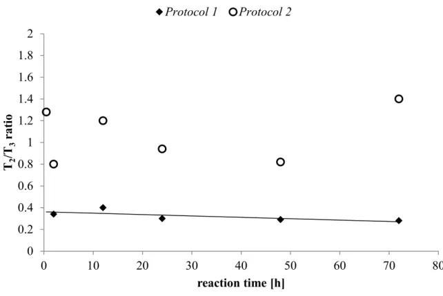
Le chapitre II est consacré à la fonctionnalisation de la CNF par le méthyltriméthoxysi-lane (MTMS) – choisi comme alcoxysiméthyltriméthoxysi-lane modèle – ainsi qu’à la caractérisation du matériau silylé. Plusieurs paramètres réactionnels (pH, temps de réaction, concentration initiale en MTMS) ont été étudiés et optimisés, à partir de deux protocoles expérimentaux distincts, nommés Protocole 1 et Protocole 2. Les modifications ont été caractérisées à l’échelle molé-culaire par différentes techniques physico-chimiques, en utilisant notamment la spectroscopie infra-rouge à transformée de Fourier (IRTF) et la Résonnance Magnétique Nucléaire en phase solide (RMN CP-MAS du 13C et du 29Si). Afin d’étudier de façon systématique l’impact des paramètres réactionnels sur la silylation de la CNF, une méthode rapide et efficace pour suivre l’évolution du taux de silane dans le matériau a d’abord été développée. A partir d’un nombre limité d’échantillons, une droite de calibration permettant de déterminer le pourcentage de si-licum à l’intérieur des échantillons, directement à partir des spectre IRTF, a ainsi été élaborée.
Les résultats présentés dans ce chapitre ont montré qu’il était possible de silyler la CNF avec le MTMS en milieu aqueux. Les deux protocoles envisagés ont conduit à des matériaux très différents, tout en préservant la structure cristalline originale de la CNF. Le Protocole 1 à conduit à un matériau constitué de particules de polysiloxane dispersées dans le réseau de CNF (Figure 2a), alors qu’avec le Protocole 2 des nanofibrilles recouvertes d’une couche de polysiloxane ont été obtenues (Figure 2b). La taille des particules et l’épaisseur des couches de polysiloxanes ont pu être contrôlées en ajustant la concentration initiale en MTMS. Les tests de lessivages ont montré que seul le Protocole 2 permettait une fixation durable du poly-siloxane à la surface de la CNF. Des différences ont également été notées en termes de mouil-labilité et de stabilité thermique. La CNF silylée issue du Protocole 1 s’est avérée hydrophile,
Les flèches blanches pointent les particules de polysiloxane
alors que le Protocole 2 a conduit à un matériau très hydrophobe. Une augmentation significa-tive de la stabilité thermique a également été notée dans ce dernier cas.
Figure 2 Photomicrographies de CNF traitée avec le MTMS selon le Protocole 1 (a) ou le Protocole 2 (b) (barre d’échelle : 10 µm). La distribution du silicium obtenue par analyse
dis-persive en longueur d’onde (WDX) est également reportée (barre d’échelle : 100 µm).
Dans le chapitre III, l’impact de la silylation sur les propriétés de composites à matrice acide poly(lactique) (PLA) ou polydiméthylsiloxane (PDMS) chargée en CNF a été évalué. Les propriétés mécaniques, la stabilité thermique et l’hygroscopicité des composites ont parti-culièrement été étudiées. Des résultats différents ont été obtenus en fonction de la matrice po-lymère utilisée.
Pour les composites à matrice PDMS chargés avec 1% de CNF, une augmentation du module de cisaillement (G’), du module d’Young (E) et de la résistance en traction ont été obtenues après silylation à partir du Protocole 2 dans certaines conditions. Par contre, une diminution
a
WDX
de la déformation à la rupture a systématiquement été mesurée et le matériau s’est avéré plus hygroscopique que le PDMS seul (mais la prise en eau reste faible).
Pour les composites à matrice PLA chargés avec 10% de CNF, aucune amélioration notable des propriétés mécaniques a été notée après silylation, voire une détérioration. Une augmenta-tion de l’hygroscopicité a été mesurée en présence de CNF (mais la silylaaugmenta-tion tend à réduire la prise en eau).
Une augmentation de la stabilité thermique des composites (PDMS et PLA) a été mise en évi-dence en présence de CNF silylée, mais aucune tendance n’a pu être établie ou corrélée avec le taux de silylation ou le type de protocole utilisé.
Dans le chapitre IV, la CNF silylée à partir du Protocole 2 a été utilisée pour produire de nouveaux matériaux moussés hydrophobes et oléophiles. Des mousses ultra-légères (≤ 17.3 Kg/m3), poreuses (≥ 99%) et possédant une faible surface spécifique (≤ 20 m2/g) ont été syn-thétisées. L’analyse microscopique a montré que la structure interne des matériaux étant ma-joritairement composée d’un réseau 3D de feuillets et nanofilaments interconnectés.
Les propriétés mécaniques des mousses ont été évaluées sous compression. Une augmentation du module d’élasticité et de la résistance à 50% de déformation ont été notées avec l’augmentation du niveau de silylation. De façon remarquable, les mousses silylées ont pré-senté une très grande élasticité par rapport au matériau de référence non modifié, la déforma-tion sous compression étant quasi réversible à partir d’un certain taux de silyladéforma-tion (Figure 3).
Figure 3 Schéma présentant la reprise en épaisseur (S) des mousses silylées après un test de
compression réalisé à 50% de déformation (ε = 50%). 61% 72% 76% 75% 82% 78% 86% 96% 0 2.1 3.5 4.4 6.8 9.1 18.9 38.1 CNF non
modifiée Elasticité augmente avec Si %
100%
ε =
50%
S [%] = 100 - ε final
Les mousses silylées se sont avérées à la fois hydrophobes et oléophiles, et se sont montrées très efficaces pour absorber sélectivement une pollution de dodecane (choisi comme huile modèle) présente à la surface de l’eau (Figure 4). Par ailleurs, le matériau silylé a pu être re-cyclé plus de 10 fois sans modification notable de sa capacité d’absorption, et sans altération de son intégrité physique.
Une diminution de la conductivité thermique des mousses a également été mise en évidence après silylation.
Figure 4 Démonstration des propriétés hydrophobes et oléophiles d’une mousse silylée à
par-tir du MTMS. L’eau et le dodécane sont colorés en bleu et en rouge, respectivement.
Eau
Dodécane
Table of content
General introduction ____________________________________________ 1
I.
Generalities ________________________________________________ 3
I.1. Chemical composition of plant fibres __________________________________ 3
I.1.1. Macromolecular substances _______________________________________ 3 I.1.2. Low molecular weight substances ___________________________________ 6 I.1.3. Chemical composition of oat straw __________________________________ 7
I.2. Structure of plant cell walls __________________________________________ 7
I.2.1. Middle lamella and primary wall ___________________________________ 8 I.2.2. Secondary wall (S) ______________________________________________ 8
I.3. Nanofibrillated cellulose (NFC): isolation and morphological characteristics _ 9
I.3.1. Nomenclature __________________________________________________ 9
I.3.2. Isolation methods _______________________________________________ 9
I.3.3. Properties of NFC ______________________________________________ 11
I.4. Applications of NFC _______________________________________________ 12
I.4.1. NFC as reinforcing agents in composites ____________________________ 13 I.4.2. NFC as matrix for the elaboration of aerogels or foams _________________ 16
I.5. Chemical functionalization of NFC ___________________________________ 20
I.5.1. Context ______________________________________________________ 20
I.5.2. Oxidation _____________________________________________________ 21
I.5.3. Esterification __________________________________________________ 22 I.5.4. Etherification __________________________________________________ 23 I.5.5. Carbamylation reactions _________________________________________ 25
I.5.6. Silylation _____________________________________________________ 26
I.5.7. Other reactions ________________________________________________ 28 I.5.8. Concluding remarks and objectives of the thesis ______________________ 30
II.
Silylation of NFC with methyltrimethoxysilane: optimization of the
II.1. Preliminary investigations __________________________________________ 33
II.1.1. Brief overview on the reactivity of trialkoxysilanes ____________________ 33 II.1.2. Calibration chart for the evaluation of the Si content from IR spectra ______ 37
II.2. Impact of reaction parameters _______________________________________ 39
II.2.1. Experimental protocols __________________________________________ 40 II.2.2. Impact of pH (Protocol 1) ________________________________________ 40 II.2.3. Impact of reaction time (Protocol 1 & 2) ____________________________ 47 II.2.4. Impact of initial silane concentration (Protocol 1 & 2) _________________ 53
II.3. Properties of silylated NFC _________________________________________ 58
II.3.1. Resistance to leaching ___________________________________________ 59 II.3.2. Crystallinity ___________________________________________________ 61 II.3.3. Wettability and hygroscopicity ____________________________________ 63 II.3.4. Thermal stability _______________________________________________ 66
II.4. Concluding remarks _______________________________________________ 69
III.
Silylated NFC as reinforcing agents in composites _______________ 71
III.1. Objectives and methodology ______________________________________ 71 III.2. PDMS composites _______________________________________________ 71
III.2.1. Viscoelastic properties __________________________________________ 72 III.2.2. Tensile properties ______________________________________________ 75 III.2.3. Thermal stability _______________________________________________ 77 III.2.4. Hygroscopicity ________________________________________________ 79
III.3. PLA composites _________________________________________________ 80
III.3.1. Crystallinity of PLA in composites _________________________________ 80 III.3.2. Viscoelastic properties __________________________________________ 81 III.3.3. Tensile properties ______________________________________________ 83 III.3.4. Thermal stability _______________________________________________ 85 III.3.5. Hygroscopicity ________________________________________________ 87
III.4. Concluding remarks ________________________________________________ 88
IV.
Utilisation of silylated NFC for the elaboration of foams __________ 89
IV.2. Silylation of NFC foams __________________________________________ 90
IV.2.1. Evolution of Si content __________________________________________ 90 IV.2.2. Solid-state NMR characterization __________________________________ 90
IV.2.3. Microscopy ___________________________________________________ 90
IV.3. Properties of silylated NFC foams __________________________________ 94
IV.3.1. Density, porosity and specific surface area ___________________________ 94 IV.3.2. Compressive properties __________________________________________ 95 IV.3.3. Wettability and hygroscopicity ____________________________________ 97 IV.3.4. Oleophilic properties ____________________________________________ 99 IV.3.5. Thermal conductivity __________________________________________ 103
IV.4 Concluding remarks ________________________________________________ 104
V.
General conclusion ________________________________________ 107
VI.
Materials and Methods____________________________________ 111
VI.1. Materials _____________________________________________________ 111
VI.1.1. Chemicals ___________________________________________________ 111
VI.1.2. Laboratory equipment __________________________________________ 111
VI.2. Production of nanofibrillated cellulose _____________________________ 112 VI.3. Silylation of NFC’s _____________________________________________ 113
VI.3.1. Protocol 1 ___________________________________________________ 113 VI.3.2. Protocol 2 ___________________________________________________ 114 VI.3.3. Protocol 2’ ___________________________________________________ 115
VI.4. Elaboration of composite films and silylated foams ___________________ 115
VI.4.1. Elaboration of PDMS-composites _________________________________ 116 VI.4.2. Elaboration of PLA-composites __________________________________ 116 VI.4.3. Elaboration of unmodified and silylated NFC foams __________________ 116
VI.5. Characterization methods _______________________________________ 117
VI.5.1. Characterization of NFC ________________________________________ 117 VI.5.2. Characterizations of composites __________________________________ 120 VI.5.3. Characterizations of NFC foams __________________________________ 122
References __________________________________________________ 127
1
General introduction
This research project was founded by the Commission for Technology and Innovation (CTI) of Switzerland and was initiated in cooperation between the Swiss Federal Laboratories for Materials Science and Technology (Dübendorf, Switzerland), the University of Bordeaux 1 (Bordeaux, France) and two industrial partners, namely: Falcone Chemical Specialities Ltd. (Siebnen, Switzerland) and Jelu-Werk Josef Ehrler GmbH & Co. KG (Rosenberg, Germany). In the context of petroleum resources depletion, new environmental regulations and spread of sustainability concerns, cellulose has increasingly drawn attention over the last three decades.1 Cellulose is the most abundant polymer on the earth, representing about 1.5 x 10¹² tons of the total annual biomass production,2 and it presents very attractive properties. Cellulose fibres have low cost, are renewable, biodegradable, have high specific strength and modulus, low density,3, 4 and can replace conventional inorganic or petroleum-based materials in composites applications.5, 6
In recent years, interest has been increasingly focused on nanocelluloses extracted from wood or plants, as exemplified by the increasing number of scientific publications and patents published since the beginning of the 21st century.7 Nanocelluloses such as cellulose nanocrystals, nanofibrillated cellulose or electro-spinned cellulose nanofibres, possess highly interesting properties related to their high aspect ratio and specific surface area, as well as good mechanical properties.8, 9 Hence, they have the potential to serve as building blocks for the elaboration of novel functional materials.7, 10-12
In particular, nanofibrillated cellulose (NFC) has been extensively considered as reinforcing agent in polymer matrices for composites application.7, 12-14 More recently, promising lightweight, flexible and robust cellulosic foams have been successfully prepared using NFC as starting material.10 However, the hydroxylated surface of these nanofibrils is often pointed out as a limiting factor for its use in commercial applications. In particular, NFC undergoes irreversible aggregation upon drying (hornification), which precludes any dry processes. Additionally, NFC fibrils cannot be ideally dispersed in non-polar solvents, monomers or polymers since the hydrophilic surface of the NFC is incompatible with hydrophobic environments (the NFC tends to aggregate by hydrogen bonding). Furthermore, the strong
2
tendency of NFC to absorb water is often undesirable in many composites and foams applications.
As most of these drawbacks and limitations are related to the chemical nature of the NFC surface, they can be suppressed or limited by chemical functionalization. For instance, hydrophobic functions can be grafted at the NFC surface to decrease the interfacial energy and increase their interaction with hydrophobic environments (physical or chemical interactions). A decrease in the hydrophilicity of the NFC composites and foams can also be obtained by this method.
As hydroxyl groups are the most reactive sites at the NFC surface, reactions based on alcohol chemistry have mostly been explored in the literature. The reactants conditions must be mild enough to limit cellulose degradation. A broad range of catalysts and solvents have been tested (in particular DMSO, DMF, toluene and hexane), but due to environmental concerns, green solvents are increasingly investigated (i.e. scCO2, ionic liquids, and water). Energy saving procedures, such as microwave-assisted reaction,15, 16 are also increasingly considered.
In this context, we envisaged monitoring the surface of NFC produced from oat straw, by developing an environmentally friendly method based on alkoxysilanes, which can be processed in water. Because a large variety of functional groups is available within commercial alkoxysilanes, it is anticipated that the method will open up opportunities to broaden the spectrum of application of NFC. In the current thesis, the potential of silylated NFC as reinforcing agents in composites and as building block for the elaboration of foams was particularly investigated.
The thesis is divided in six chapters:
Chapter I presents some general aspects about nanocelluloses – in particular NFC - and their use in composite materials and foams.
Chapter II is dedicated to the functionalization of NFC by methyltrimethoxysilane – chosen as a model silane – and to the comprehensive examination of the silylated materials. Reaction conditions such as pH, reaction time and initial silane concentration have been particularly investigated and optimized using two distinct experiment protocols. The modifications have been characterized at the molecular level by various physicochemical techniques. The
3
properties of the silylated nanofibres, i.e. the morphology, crystallinity, wettability, hygroscopicity and thermal stability have been subsequently examined.
Chapter III investigates the impact of silylation on the mechanical, thermal and hygroscopic properties of NFC-reinforced composites prepared with two distinct polymeric matrices: polydimethylsiloxane (PDMS) and poly(lactic acid) (PLA).
Chapter IV examines the impact of silylation on the properties of NFC-foams prepared by freeze drying, in particular the porosity, compressive properties, wettability, hygroscopicity, oleophilicity and thermal conductivity
A general conclusion is drawn in Chapter V and some outlooks are proposed.
Finally, the materials and methods that have been employed throughout this thesis are described in Chapter VI.
I. Generalities
I.1.
Chemical composition of plant fibres
I.1.1. Macromolecular substances
I.1.1.1. Cellulose
Cellulose can be extracted from different plants and animals, for example, wood, cotton, bamboo, cereal straw (wheat, oat, rice etc.), algae, bacteria, animal tunicates, etc.17, 18 This linear polymer is composed of D-anhydroglucopyranose units (AGU) which are linked by β-1,4-glucosidic linkages. The polymer chain contains one hemiacetal reducing end, and a non-reducing end with a hydroxyl group in the C4 position (Figure 1).19, 20
Figure 1: Molecular structure of cellulose highlighting the non-reducing end (free hydroxyl at the C4 position) and the reducing end with a hemiacetal group.
4
The degree of polymerization (DP) depends on the source and treatment used to isolate the polymer. In general, the DP of cellulose obtained from cotton fibres is 8,000-14,000, cotton linters 1,000-6,500, bagasse 700-900 and wood fibres 8,000-9,000.21 To our knowledge, the value of DP of cellulose from oat straw (used in the present thesis) is not available in the literature.
In plant fibres, cellulose chains interact with each other through hydrogen bonds, forming bundles of fibrils (or microfibrillar aggregates), in which highly ordered regions (i.e. crystalline phases) alternate with disordered domains (i.e., amorphous phases).4 The formation of intra- and intermolecular hydrogen bonds have been the subject of many studies.22-24 While there is only one possibility of hydrogen bonding between O3-H▪▪▪O5, there are different possibilities for O2-H and O6-H. An example of such hydrogen bonds network between two cellulose chains in Cellulose I is presented in Figure 2.23
Figure 2: Schematic representation of hydrogen bonds in cellulose Iβ.23 Black: Carbon, red: Oxygen, white: hydrogen of methyl group, green: hydrogen of hydroxyl group; dotted line: hydrogen bonds. Only the oxygen atoms involved in hydrogen bonding are labelled.
The crystallinity degree depends on the source and treatment of the materials. For example, the crystallinity degree of natural fibres such as cotton, ramie, flax, sisal, and banana is about 65%, while that of regenerated cellulose is about 35%. Four polymorphs of cellulose have been characterized so far in the literature.25, 26 Cellulose I is the structure of native cellulose, while other polymorphs are obtained by different chemical treatments of Cellulose I. Cellulose II is usually obtained after regeneration of native cellulose, or by the mercerization process (treatment with sodium hydroxide). Cellulose III is formed when Cellulose I or II is
5
modified with organic amines or liquid ammonia, while Cellulose IV is obtained after a thermal treatment of Cellulose III.19 Each polymorph is defined by its unit cell parameters.25 Cellulose I has two polymorphs, Iα and Iβ, which coexist in different proportions depending on the sources – Iα is dominant in bacterial and algal celluloses, whereas Iβ is dominant in plants and tunicates.27, 28 In the present study the cellulose source was oat straw, therefore the term “cellulose” refers to native cellulose, namely Cellulose I.
I.1.1.2. Hemicelluloses
Hemicelluloses are a heterogeneous group of branched matrix polymers of relatively low molecular weight. Whereas cellulose contains only glucose, hemicellulose contains a variety of sugars such as glucose, mannose, xylose, arabinose etc.19 Hemicellulose molecules are tightly hydrogen bonded to the cellulose microfibrils, acting as a cross-linking matrix between cellulose and lignin.17 The main monomers constitutive of hemicelluloses are presented in Figure 3.
Figure 3: The main monomers constitutive of hemicelluloses.20
I.1.1.3. Lignin
Lignin is a very complex polymer composed of highly branched aromatic-aliphatic moieties.20 In the plant, lignin is synthesized through dehydrogenative polymerization of three monolignol precursors: p-coumaryl alcohol, coniferyl alcohol and sinapyl alcohol. An example of lignin structure is presented in Figure 4.29
6
Figure 4: The three fundamental lignin monomer precursors20 (left) and a model of lignin structure29 (right).
Cellulose and hemicelluloses are closely bound by lignin, which provides rigidity and cohesion to the cell wall, and acts as barrier against moisture or microbial attacks.30
Figure 5: Representation of lignocellulose structure31
I.1.2. Low molecular weight substances
I.1.2.1. Extractives
The term extractives is related to a heterogeneous group of substances, which can be extracted from wood or plants using solvents like methanol, ethanol, acetone, toluene or dichloromethane.32 Extractives in oat straw are mainly free fatty acids, resin, sterols and waxes.32
I.1.2.2. Mineral substances
Minerals are essential for the growth of plants.32 They remain in the form of ash, after combustion of the lignocellulosic material. The main mineral in oat straw is SiO2, which
7
represents 65-70% of the total mineral content. It has been reported to contribute to the plant growth and antimicrobial resistance,32 as well as to the rigidity of the stem.33 The other minerals are macro- and micronutrients, such as N, P, S, Ca, and Fe, Mn, Zn, Cu etc.32
I.1.3. Chemical composition of oat straw
The chemical composition of oat straw has been reported by different authors, with some variations (Table 1).
Table 1: Chemical composition of oat straw in literature (in w/w %):
Ref. Water solubles Cellulose Hemicelluloses Lignin Wax Ash
Sun34 4.6 38.5 31.7 16.8 2.2 6.1
Theander35 Proteins Cellulose Hemicelluloses Lignin Extractives Ash
4.5 33 31 18 7.4 6.0
Adapa36 Cellulose Hemicelluloses Lignin 25.4±1.0 21.7±0.9 19.6±0.6
I.2.
Structure of plant cell walls
The plant cell walls consist of cellulose microfibrils, which are embedded in a highly crosslinked amorphous hemicellulose-lignin matrix.37 The structure of a natural fibre cell wall can be assimilated to a microscopic tube composed (from exterior to in interior) of a middle lamella, a primary wall, a secondary wall and finally the lumen (Figure 6).17
Figure 6: Structural constitution of a plant fibre cell.18
In the cell wall, elementary fibrils (Ø = 1.5 to 3.5 nm)2 aggregate into microfibrils (Ø = 2 to 50 nm)19, which further form microfibrillar bands (width in range of 100 nm)2. The microfibril angle (i.e. the angle between the direction of the helical windings of cellulose
8
microfibrils and the long axis of cell) plays a central role in determining the mechanical behaviour of the plant.38
I.2.1. Middle lamella and primary wall
The middle lamella is a thin layer composed of hemicellulose and lignin, which glues the cells together.30 It has primary walls on both sides.
The primary wall is a thin layer of about 0.1-0.2 µm, consisting of cellulose, hemicellulose, pectin and protein, all embedded in lignin. In the primary wall, the microfibrils orient in random manner, building a netlike texture.38
The term “compound middle lamella” (CML) generally refers to the middle lamella plus adjacent primary walls.30
I.2.2. Secondary wall (S)
I.2.2.1. S1
The outer layer (S1) is thin (0.2-0.3 µm) and forms 10-20% of the total cell wall.38 In the S1 layer, microfibrils are arranged in tightly wound helices, at a nearly transverse orientation (60-80° to the cell axis).19
I.2.2.2. S2
The middle layer (S2) is thick (1-5 µm) and forms 70-90% of the total cell wall.38 In the S2 layer, the microfibrils are densely packed and orient helically at a relatively small angle (5-30°) to the cell axis.19
I.2.2.3. S3
The inner layer (S3) is the thinnest layer (about 0.1 µm), forming 2-8% of the total cell wall.38 In the S3 layer, the microfibrils are arranged again in tightly wound helices, at a nearly perpendicular orientation (60-90° to the cell axis).19
9
I.3.
Nanofibrillated cellulose (NFC): isolation and morphological
characteristics
I.3.1. Nomenclature
The nomenclature concerning micro- and nanomaterials from natural resources has not been standardized yet. Different terms are used according to recent review papers:7, 39
• “Microcrystalline cellulose (MCC)” refers to commercial cellulose materials, applied mainly in pharmaceutical and food industry. The diameter of this material is generally greater than 1 µm;7, 39
• “Microfibril” refers to fibrous cellulose structures formed during the biosynthesis in higher plants. Synonyms which can be found in the literature are nanofibril, nanofibre;7 • “Microfibrillated cellulose (MFC)” or “Nanofibrillated cellulose (NFC)” refers to
microfibril aggregates produced by mechanical refining of plant fibres.39 In the present work, only the term “nanofibrillated cellulose (NFC)” was used;
• “Cellulose nanocrystals (CNC)” refers to rod-like shaped cellulose nanoparticles obtained after acid hydrolysis of pulp, MCC or NFC. Synonyms which can be found are cellulose whiskers, nanowhiskers, rod-like cellulose crystals.7, 39
The average dimensions that have been reported for each type of cellulosic material are presented in Table 2:
Table 2: Dimensions of the micro- and nano-scaled cellulose materials, isolated from natural fibres
Type Diameter d [nm] Length L [µm] Aspect ratio (L/d)
MCC7 >1,000 >1 ~1
Microfibril7 2-10 >10 >1,000 MFC/NFC7, 39 4-40 5-10’s 100-150
CNC7, 39 3-5 0.1-0.6 10-100
I.3.2. Isolation methods
The processes for the isolation of nano-celluloses have been reviewed comprehensively by Moon et al.39 They are produced from purified fibres, after elimination of hemicelluloses, lignin, etc. Different approaches have been used separately, in sequence or in combination.
10
I.3.2.1. Isolation of cellulose nanocrystals (CNC)
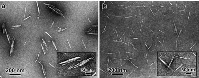
CNC can be produced by acidic hydrolysis of the starting cellulosic material. This simple process usually involves a partial acid hydrolysis of cellulose using concentrated sulfuric acid (H2SO4), which removes disordered or paracrystalline regions of cellulose and leaves crystalline regions intact. After this treatment, rod-like shaped cellulose nanocrystals bearing anionic sulfate ester groups at their surface are produced. Their geometrical dimensions generally depend on the starting cellulose source, resulting in values varying from 5 to 20 nm in width, and from 100 nm to 1-2 µm in length (Figure 7).40, 41
Figure 7: TEM micrographs of CNC obtained by sulfuric acid hydrolysis of cotton (a), and MCC (b).40
I.3.2.2. Isolation of nanofibrillated cellulose (NFC)
Nanofibrillated cellulose (NFC) is generally produced by mechanical disintegration. This process generally involves a refining step followed by a high-pressure homogenization step,42, 43
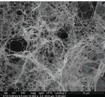
but cryocrushing and grinding methods have been also reported.44, 45 The mechanical treatments produce a network of interconnected cellulose microfibrils, with diameters from 10 to 100 nm and aspect ratios from 50 to 10046-48 (Figure 8).
11
Figure 8: SEM micrograph of NFC, mechanically isolated from oat straw cellulose powder12
In order to decrease the high energy consumption associated with these processes, chemical pre-treatments of the cellulose raw material have been also envisaged: TEMPO,49-53 carboxymethylation,54-56 periodate oxidation,57 and enzymatic58-60 modifications.
I.3.3. Properties of NFC
I.3.3.1. Mechanical properties of isolated NFC
The mechanical properties of isolated NFC cannot be easily evaluated because of the variability of the NFC material. Only information about single plant fibers or crystalline regions could be found in the literature. For single plant fibres, E modulus in the range of 5-45 GPa and tensile strength in the range of 0.3-0.8 GPa have been reported, based on Raman techniques.14, 61, 62 For the crystalline regions, E modulus between 124 and 155 GPa63 and tensile strength up to 7 GPa39 have been reported (evaluated experimentally or using modelling).
I.3.3.2. Properties of NFC films
One of the most interesting features of NFC stems from its excellent film forming properties. NFC films are mainly obtained through solution casting, a process during which the solvent (mostly water) is removed by evaporation, vacuum filtration, pressing, or a combination of these processes.59, 64 The nanofibrils in the dried films cannot be re-dispersed in water, due to the irreversible agglomeration of cellulose nanofibres upon drying. This phenomenon is
12
called hornification and is explained by the formation of additional hydrogen bonds between amorphous parts of the cellulose fibrils during drying.65, 66
a) Mechanical properties
Excellent mechanical properties in tension mode have been reported in the literature for NFC films, with values in the range of 1-17.5 GPa and of 20-240 MPa for E-modulus and tensile strength, respectively.39 These values are lower than those obtained for crystalline cellulose, because of the presence of amorphous regions in NFC and because of the random in-plane nanofibril orientation within the film.39 Nevertheless, if the density of cellulose (1500 kg/m3)67 is taken into consideration, the mechanical properties of NFC films are comparable with metals and ceramics.39
b) Optical properties
NFC films are generally characterized by their medium to low transparency, which is associated to the light scattering caused by different phenomena: high fraction of air in the films (porosity ~20-40%); difference of refractive index between air and cellulose (air: ~1.0; NFC: 1.618 along the fibril, 1.544 in the transverse direction68), nanofibrils sizes, film thickness and surface roughness.39
c) Barrier properties
Concerning barrier properties, significant water sorption (15 % at 90 % RH)59 and water permeability values (321 ± 46 g m-2 day-1)69 have been measured, because of the highly hydrophilic nature of cellulose. But excellent barrier properties towards oxygen have been often reported, with oxygen transmission rate (OTR) values down to 17.8 ml m-2 day-1 measured for NFC films with a thickness of 20-30 µm.70
I.4.
Applications of NFC
As mentioned above, NFC has many interesting properties related to its nano-size dimensions and chemical structure, which makes it an interesting candidate for various applications. In particular, NFC has been extensively studied as reinforcing agent in polymer matrices for composites application.7, 12-14 More recently, promising lightweight, flexible and robust cellulosic foams have been prepared using NFC as starting material.10 These two applications will be developed in the next paragraph.
13
I.4.1. NFC as reinforcing agents in composites
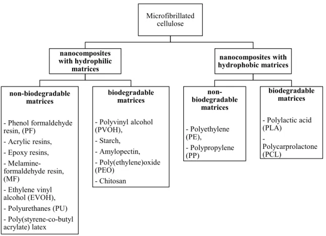
A wide range of polymer matrices have been reinforced with NFC, but the majority of the studies involved hydrophilic matrices, because of the good compatibility with the hydrophilic NFC. An overview of the most popular matrices reinforced with NFC can be found in the classification below (Figure 9).7
Figure 9: Classification of nanocelluloses reinforced polymer composites, summarized by Siró et al.7
I.4.1.1. Methods for the processing of NFC composites
Several preparation methods have been envisaged to elaborate NFC-reinforced polymer composite materials. In the most popular approaches, NFC is dispersed in a solvent containing the dissolved polymer, and is subsequently processed by techniques such as solution casting,47, 71-74 melt compounding75, 76 or electrospinning.77 These methods are limited by the amount of NFC that can be incorporated in the suspension, which cannot exceed 30 wt %.39
In order to increase the NFC ratio in the composite material, a three steps process can be envisaged, which consists in: i) elaborating a NFC film through a solvent casting process, ii)
Microfibrillated cellulose nanocomposites with hydrophilic matrices non-biodegradable matrices - Phenol formaldehyde resin, (PF) - Acrylic resins, - Epoxy resins, - Melamine-formaldehyde resin, (MF) - Ethylene vinyl alcohol (EVOH), - Polyurethanes (PU) - Poly(styrene-co-butyl acrylate) latex biodegradable matrices - Polyvinyl alcohol (PVOH), - Starch, - Amylopectin, - Poly(ethylene)oxide (PEO) - Chitosan nanocomposites with hydrophobic matrices non-biodegradable matrices - Polyethylene (PE), - Polypropylene (PP) biodegradable matrices - Polylactic acid (PLA) - Polycarprolactone (PCL)
14
impregnating the dried film with the desired resin and iii) oven drying the film with or without hot pressing.59, 64 Composite materials with NFC contents above 70 wt % have been reported with this technique.39
Another technique based on a wet-laid process (papermaking-like) has been also reported, and allowed the preparation of NFC/PLA composites with NFC weight fraction up to 90 %.78
The incorporation of NFC in the polymer melt73 or the polymerization of the monomer “in-situ”79 have been also proposed in two recent studies.
I.4.1.2. Mechanical properties of NFC composites
As compared with neat polymer matrices, an increase of both E modulus and tensile strength, with a concomitant decrease of the strain at break, have been reported with composites prepared from hydrophilic polymers such as PVOH47, HPC47, PF80, MF59, poly(styrene-co-butyl acrylate)latex81 and PU.82
The reinforcing effect of NFC in composites with hydrophobic matrices has shown mixed results. Wang and Sain,83, 84 incorporated NFC into molten PE and PP, using acrylic oligomers as dispersant, but the mechanical properties of these composites did not show significant improvement. The most studied hydrophobic matrix is PLA, because of its 100 % renewable nature.7 PLA has some shortcomings, such as brittleness and low thermal stability.7 Several attempts have been made to reinforce PLA by NFC using different processing methods, such as solution casting72, 85, extrusion86, 87 or wet-laid processing78. A slight increase in modulus and tensile strength has been noted,78, 85, 86 but aggregation occurs during processing and poor mechanical properties are still displayed by the composite.87
I.4.1.3. Optical properties of NFC composites
Optically transparent NFC composites were prepared by Iwamoto et al.44, 64 by impregnating a dry NFC film with acrylic resins, followed by UV curing. Light transmittance between 70 and 85 % was obtained, with up to 70 wt % NFC dispersed in the matrix. The transmittance in such composites depends on refractive index match, film thickness, nanocelluloses dimensions and volume fraction (Figure 10).39
15
Figure 10: Factors impacting the light transmittance of CN/resin composites.39 (CN refers to different types of nanocelluloses, such as NFC and CNC)
I.4.1.4. Thermal properties of NFC composites
In general, the thermal stability of the NFC-reinforced composites tend to increase with increasing weight fraction of NFC, as demonstrated with matrices such as PLA,74, 88, 89 cellulose acetate,90 melamine formaldehyde resin59 or amylopectin.91 This is particularly the case in the temperature range higher than glass-transition temperature (Tg).39
The coefficient of thermal expansion (CTE) is another important parameter for applications such as flexible transparent displays.92 Iwamoto et al.44, 64 found that a significant decrease in CTE could be obtained when NFC were incorporated into acrylic matrices. The CTE tended to decrease with increasing crystallinity of NFC.93
I.4.1.5. Barrier properties of NFC composites
The barrier properties to oxygen have been improved by addition of NFC in amylopectin films.94 The oxygen transmission rate (OTR) was found to decrease with increasing NFC content.
Water sorption is regarded as one of the major issues that limits the application of NFC-polymer composites, due to the hydrophilic nature of cellulose. Hence, when hydrophobic polymer matrices are used, the water sorption of the composites is generally higher than that of the neat polymer.72 Water sorption has been shown to decrease in some rare cases, as
16
demonstrated by Henriksson et al. with melamine formaldehyde matrices.59 But if hydrophilic matrices such as starch are used, a reduction in water sorption can be measured.95-97
To obtain better barrier properties, some authors have envisaged incorporating nanoclays in combination with NFC and obtained a reduction in both water sorption and oxygen permeability.98, 99
I.4.2. NFC as matrix for the elaboration of aerogels or foams
I.4.2.1. Definitions
Aerogels and foams are ultra-light weight and highly porous materials that are prepared by the replacement of a liquid solvent in a gel by air. The term “aerogels” is generally employed to name materials in which the typical structure of the pores and the network is mostly maintained, i.e. the gel structure does not change after replacement of the liquid by air (shrinkage phenomena are minimized).100 If the network structure has changed, the more general term “foam” is preferred. In present study, the term “foam” will be used for any porous material prepared from NFC.
Brought to light in 1931,101 these porous materials are mostly elaborated through the Sol-gel® polymerisation of inorganic metal oxides, such as silica, alumina, titania, zirconia or tin oxides.100, 102 The interest in such materials lies in their low density (typically between 0.004 and 0.500 g/cm3), high porosity (typically greater than 80%), high specific surface area, low thermal conductivity, excellent shock absorption and low dielectric permittivity.100, 102, 103 Hence, aerogel materials have been used in various applications including thermal and acoustic insulation, paints, electrical applications, life science, catalysis or optical applications.102
But these materials generally suffer from their brittleness. To overcome this problem, alternative lightweight, flexible and robust cellulosic aerogels or foams have been proposed using NFC as starting material.104-106 Since aqueous NFC suspensions have gel-like properties, due to the presence of long and interconnected hydrophilic cellulose nanofibrils, replacing water with air results in an aerogel or foam with long entangled cellulose nanofibres.
I.4.2.2. Methods for the processing of NFC foams
17
- With the freeze-drying method, the NFC suspension is frozen in a mould and water is eliminated by sublimation (Figure 11).106-109 Alternatives consist in first solvent-exchanging water with t-butanol, and then freeze-drying the alcoholic suspension.104, 108
In that case, the foam obtained is more homogeneous and displays a higher specific surface area.
- The supercritical CO2 drying method (scCO2 drying) is performed in two steps: i) water is solvent exchanged with organic solvents miscible with CO2, such as ethanol or acetone; ii) the organic solvent is solvent-exchange with CO2. The disadvantage of this process is that it is time consuming.110
Figure 11: Image of NFC foam prepared by the freeze-drying method.104
I.4.2.3. Morphology of NFC foam
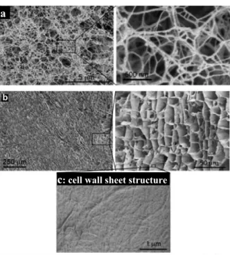
With the freeze-drying method, different morphologies can be obtained depending on the speed with which the freezing step is performed. If the NFC suspension forms a thin layer in the mould (1-3mm), the freezing is so fast that that a porous structure composed mostly of nanofilaments is obtained (Figure 12a).108, 109, 111 When the thickness of the NFC gel exceeds this range, aggregation of nanofibrils starts to occur and two types layers are formed: i) the bottom layer, which freezes quickly, is composed of nanofilaments (Figure 12c); ii) the layer above, which freezes slowly, is composed of cell wall sheet structures (Figure 12b), resulting from the agglomeration of cellulose nanofibres during freezing.104, 108 This phenomenon arises because the ice crystals formed during slow freezing tend to push the cellulose nanofibres into the interstitial regions of the crystals.112
18
Figure 12: SEM images of NFC foams obtained by freeze-drying: a) Fast freezing (bottom layer); b-c) Slow freezing (layer > 3 mm).111
With both the t-butanol freeze-drying and scCO2 drying methods, a porous structure composed mainly of nanofilaments is obtained (Figure 13).104, 113 As t-butanol has a much lower expansion coefficient than water, the cellulose nanofibrils are not squeezed during freezing.100 In the case of the scCO2 method, no freezing step is involved.
Figure 13: SEM micrographs of NFC aerogels prepared by t-butanol freeze drying (a and b)104 and supercritical CO2 drying (c)113
I.4.2.4. Density, porosity and specific surface area
The density, porosity and specific surface area are directly impacted by the method of processing (i.e. the nature of the fibrillar network) and the concentration of NFC in the original suspension, as demonstrated by the data presented in Table 3:
c: cell wall sheet structure
c b
a
19
Table 3: Density (ρ), porosity and BET surface area of various NFC foams produced by different methods
Ref. Drying process NFC
concentration [wt%] ρ [kg/m3] porosity [%] BET surface area [m2/g] Pääkkö109 Vacuum pumping freeze drying 2 30 95-98 20 Cryogenic freeze drying 2 20 98 66 Sehaqui113 t-BuOH freeze drying ~15 380 74 117 scCO2 drying ~15 205 86 304 Sehaqui106 Cryogenic freeze drying 0.7 7 99.5 44 6.0 61 95.9 ~15 10 103 93.1 15
I.4.2.5. Mechanical properties of NFC foams
Besides the high porosity and specific surface area, NFC foams provide interesting mechanical characteristics compared with other foams. The E modulus and compressive yield strength of the foams increases with increasing density, which can be controlled by varying the concentration of NFC in the original suspension.106 The energy of absorption in compression of NFC foams is generally higher than that of polymer foams such as expanded polystyrene foams.111 Nevertheless, NFC foams have been reported to have limited shape recovery after compression.105 Table 4 presents the mechanical properties of some NFC foams prepared with the freeze-drying method:
Table 4: Mechanical properties of NFC foams prepared with the freeze drying method111
NFC concentration [wt%] 0.7 2.2 4.2 10
Density [kg/m3] 7 22 43 103
Porosity [%] 99.5 98.5 97.2 93.1
E Modulus [kPa] 56 435 1510 5310
Yield stress [kPa] 7.8 31.9 135.1 515.6
20 I.4.2.6. Application of NFC foams
For the time being, NFC foams have been mostly tested as reinforcing agents in composites or as porous templates. Amylopectin and PVOH reinforced NFC foams have been shown to display an increase in E modulus of up to 40%.97, 112. Conducting foams have been prepared by dipping the NFC foams in a solution of polyaniline.109 Photoswitchable or magnetic NFC aerogels have been produced by chemical vapour deposition of TiO2,114 or precipitation of magnetic nanoparticles,115 respectively.
I.5.
Chemical functionalization of NFC
I.5.1. Context
NFC possesses many interesting properties, but its hydroxylated surface is often pointed out as a limiting factor for its use in commercial applications. In particular, NFC undergoes irreversible aggregation upon drying (hornification), which precludes any dry processes. Hence, NFC is generally processed in the form of water suspensions (max. solid content 30 %), which causes high transport and storage costs, and favours microbial degradation. Additionally, NFC fibrils cannot be ideally dispersed in non-polar solvents, monomers or polymers since the hydrophilic surface of the NFC is incompatible with hydrophobic environments (the NFC tends to aggregate by hydrogen bonding). Furthermore, the strong tendency of NFC to absorb water is often undesirable in many composites and foams applications.
As most of these drawbacks and limitations are related to the chemical nature of the NFC surface, they can be suppressed or limited by chemical functionalization. For instance, the introduction of surface charge by oxidation can be a successful pathway to limit the aggregation of the nanofibres upon drying and subsequently reduce the shipping cost of NFC. In another approach, hydrophobic functions can be grafted at the NFC surface to decrease the interfacial energy and improve their interaction with hydrophobic environments (physical or chemical interactions). A decrease in the hydrophilicity of the NFC composites and foams can be also obtained by this method.
As hydroxyl group is the most reactive sites at the NFC surface, reactions based on alcohol chemistry have mostly been explored in the literature. A broad range of catalysts and solvents have been tested (in particular DMSO, DMF, Toluene and hexane), but due to environmental concerns, green solvents are increasingly investigated (i.e. scCO2, ionic liquids, and water).
21
Energy saving procedures, such as microwave-assisted reaction,15, 16 are also increasingly considered.
A broad range of chemical modifications have been reported with microcrystalline cellulose, pulp or paper,116, 117 but we will focus here on literature related to NFC.
I.5.2. Oxidation
I.5.2.1. TEMPO-oxidation
2,2,6,6-tetramethylpiperidine-1-oxyl (TEMPO) mediated oxidation is used to produce negatively charged NFC at the surface. The reaction is selective to the primary alcohol at the C6 position of the anhydroglucose unit (Scheme 1).51 This reaction was performed in aqueous system. O CH2OH OH OH O O N O NaClO NaBr H2O, pH=10-11 O OH OH O O O O Na n n
Scheme 1: TEMPO oxidation of NFC surface
The utilisation of this method as a pre-treatment before mechanical disintegration of cellulose pulp proved to be very efficient in reducing the energy consumption associated with the production of NFC.49-53
In addition, TEMPO-oxidation of NFC led to films displaying high light transmittance, good mechanical properties, low thermal expansion and excellent oxygen barrier property.50, 113, 118 But the thermal stability was poor and the film was very hydrophilic.50
Recently, TEMPO-oxidized NFC has been used as template to prepare hybrid organic-ceramic aerogels with TiO2 or TiO2/SiO2, which showed high adsorption towards organic molecules and photocatalytic activity.119
22 I.5.2.2. Other oxidation routes
By pre-treating cellulose pulp with periodate and sodium bisulfite before mechanical disintegration, Liimatainen at el. obtained a similar effect than with the TEMPO-oxidation method (Scheme 2).57 O HO O OH OH * * NaIO4 - NaIO3 - H2O O O OH O * * O 2 NaHSO3 O O OH OH * * HO SO3 SO3 Na Na
Scheme 2: Regioselective periodate oxidation and sulfonation of cellulose pulp57
Stenstad et al.120 used ammonium cerium(IV) nitrate as a powerful oxidation agent for the post-oxidation of NFC, with the objective to further react the oxidized NFC with glycidyl methacrylate (Scheme 3).
Scheme 3: Oxidation of 1,2-glycol groups of cellulose by Ce4+.120 I.5.3. Esterification
Among the different methods that have been studied so far, the NFC esterification with anhydride molecules has received the most attention (Scheme 4).
R' O R'
O O
R' O
Dif f erent conditions
+ R' OH O NFC-OH O NFC
Scheme 4: Esterification of NFC with anhydrides
The most commonly used anhydride is acetic anhydride, which has been employed either as a fibrillation pre-treatment121-123, or for the post-modification of NFC.72, 124-126 Catalyst such as pyridine,72, 123, or perchloric acid in combination with acetic acid,121, 122, 125 have been reported,
23
but the reaction could be also performed without catalyst.124, 126 Other anhydrides, such as trifluoroacetic anhydride, have been also envisaged.127
In comparison with neat NFC, acetylated NFC (ac-NFC) can be more easily dispersed in organic solvents of low polarity such as chloroform.72 It is also more hydrophobic123, 127 and displays a low coefficient of thermal expansions (CTE).124, 125 But slightly poorer mechanical properties have been also noted in film124 or aerogels,126 probably because of weaker fibre-fibre interactions. Regarding the barrier properties, oxygen permeation was found to increase after acetylation, but water sorption decreased.72, 124, 126
Ac-NFC has been incorporated in polymer matrices, such as PLA72, 122, 123 or acrylic resins121, 124, 125
, but mixed results were found regarding the mechanical performances. In some studies, a reinforcing effect was measured,72, 121 but in other ones, no significant improvement was noted.123 Thermomechanical properties72, 122, 123 and transmittance 121, 122, 124, 125 were generally improved after acetylation.
I.5.4. Etherification
Etherification is an important method for the industrial production of cellulose derivatives. Since the first production of methylcellulose at the beginning of last century, cellulose ethers such as methylcellulose, carboxymethylcellulose and hydroxyethylcellulose have become one of the most important commercial cellulose derivatives.116
The etherification of NFC has been mostly conducted using halogenated or epoxy-based reactants, through nucleophilic substitutions and ring-opening reactions, respectively.
I.5.4.1. Reaction with halogenated molecules
The carboxymethylation reaction has been used to introduce negative charges at the NFC surface (Scheme 5).54-56 In contrast to TEMPO oxidation, this reaction is not selective to primary alcohols.
Scheme 5: Carboxymethylation of NFC with chloroacetic acid sodium salt
O Cl O Na EtOH/Isopropanol NaOH (aq.) NFC-OH O O O Na NFC + HCl
24
Similarly to TEMPO oxidation, this reaction has been applied as a pre-treatment before mechanical disintegration, to decrease the energy consumption in NFC production.54-56 The post-carboxymethylation of NFC has been also envisaged in some papers.56, 128
Films prepared from carboxymethylated NFC (cm-NFC) displayed a high transparency,55, 129 improved mechanical properties130 and excellent oxygen barrier properties129. The dried cm-NFC can be easily re-dispersed in water, indicating that the treatment prevents fiber hornification.56 But like in the case of TEMPO-oxidized NFC, the thermal-stability of NFC decreases after carboxymethylation,56 while the hydrophilicity increases.129
Different application fields have been reported for cm-NFC. They have been shown to reinforce hydroxypropyl cellulose matrices.128 They have been also used to prepare polyelectrolyte multilayers for sensor applications, taking advantage of the strong interactions existing between the negatively charged cm-NFC and positively charged polyelectrolytes.54, 55 Aerogels of cm-NFC have been investigated, with the objective to prepare porous materials with tuneable oleophobicity.131 By coating paper with cm-NFC, an increase in oil resistance and air permeability was also obtained.129
Etherification can be also used to introduce positive charges at the NFC surface, by reacting NFC with choline chloride (Scheme 6):132
Cl N Cl O N NaOH/DMSO /DMSO NFC-OH NFC + HCl
Scheme 6: Cationic functionalization of NFC with choline chloride.132
These cationic nanofibres have been used in combination with anionic clays to produce functional films with oxygen and water barrier properties, for packaging applications.69, 98, 99
I.5.4.2. Reaction with epoxides
Pei et al.133 used another etherification route to prepare cationic NFC: they first modified cellulose pulp with glycidyltrimethylammonium chloride (Scheme 7), then subsequently passed the etherified material in a microfluidizor. The quaternized NFC obtained was able to adsorb anionic dyes from aqueous systems.
25 O N Cl N NaOH Cl OH NFC-OH O NFC
Scheme 7: Etherification of NFC with glycidyltrimethylammonium chloride
In another study, ring-opening etherification was used to introduce azidealkyne groups (Scheme 8), which were further grafted by click chemistry (Scheme 12).134
O N3 NaOH i-PrOH/H2O NFC-OH NFC O Cl Cl OH N3 NaN3 AcOH NaNO2 HNO3 NaOH O N3 OH
Scheme 8: Etherification of NFC with 1-azido-2,3-epoxypropane.134 I.5.5. Carbamylation reactions
Carbamylation with isocyantes is another route to covalently bond organic functions on the surface of NFC (Scheme 9).
NFC-OH
O C N R
Water-f ree conditions
O H N
O
R NFC
Scheme 9: Carbamylation of NFC with isocyanates
Siqueira et al.135, 136 have used this functionalization pathway to introduce hydrophobic n-octadecyl chains at the NFC surface and to reinforce poly(ε-caprolactone) matrices. This carbamylation process was further studied by Missoum et al.,137 to better understand the influence of degree of substitution on final properties. Stenstad et al.120 grafted hexamethylene diisocyanate at the NFC surface, which they further cross-linked into a hydrophobic polymer layer, or reacted with amines to introduce positive charge at the NFC surface.
26
I.5.6. Silylation
I.5.6.1. Reaction with chlorosilane
Chlorosilanes can react with NFC hydroxyl groups according to Scheme 10. This reaction liberates HCl as a by-product, which is generally trapped by amine-based molecules.138
+ Cl Si CH3 CH3 Si CH3 CH3 + HCl dry toluene imidazole RT, 16h NFC-OH NFC-O
Scheme 10: Silylation of NFC with isopropyldimethyl-chlorosilane138
The reaction with isopropyldimethylchlorosilane (IPDMSiCl) in anhydrous toluene allowed producing highly hydrophobic nanofibres, which could be dispersed in THF, toluene, diethyl ether, chloroform, dichlormethane and rapeseed oil.138, 139 The silylated NFC were shown to be very effective at stabilizing water-in-toluene emulsions, via a “Pickering” process.140, 141
Chemical vapour deposition (CDV) has been also envisaged, to graft various chlorosilanes on NFC foams.131, 142-144 The main purpose and achievement of these works was to create super-hydrophobic materials with tunable oleophilicity/oleophobicity, which could float on the water surface and show selective absorption of non-polar solvents and oil.
I.5.6.2. Reactions with trialkoxysilanes
Alkoxysilanes react with hydroxylated substrates such as cellulose, according to the sol-gel process presented in Scheme 11. Compared with the chlorosilane silylation, the grafted silane structure is rather complex and depends on reaction conditions. Alcohol/water mixtures are generally used as solvent.
27
Scheme 11: Silylation of NFC with trialkoxysilanes145
With this method, Andresen et al.146 prepared silylated NFC films which showed antibacterial activity on the surface, using octadecyldimethyl(3-trimethoxysilylpropyl)ammoniumchloride (ODDMAC) in methanol/water (90/10).
Tingaut et al.147 performed silylation with vinyltrimethoxysilane (MeOSiVi) or 3-mercaptopropyltrimethoxysilane (MeOSiSH) to introduce vinyl or thiol group at the NFC surface for further thiol-ene coupling with click chemistry (Scheme 14).
Qu et al.145 performed the mechanical disintegration of cellulose pulp in ethanol to produce an NFC suspension which was further modified with 3-methacryloxypropyltrimethoxysilane (MEMO). Polylactic acid (PLA) nanocomposites reinforced with the MEMO-modified NFC displayed improved mechanical properties, but the thermal stability of the NFC decreased after silylation.
Lu et al.148 modified NFC with (3-aminopropyl)triethoxysilane (APS) and 3-glycidoxypropyl-trimethoxysilane (GLYMO) in acetone, and incorporated the silylated NFC in epoxy resins. They observed an increase in storage modulus of the epoxide composites when NFC was modified with the aminosilane.
Frone et al.149 modified NFC with APS in ethanol/water mixture prepared PLA composites which displayed better interfacial adhesion after silylation.
Qua et al.150 performed the GLYMO silylation during the disintegration process, when preparing the NFC. This is the only work reporting silylation in a 100% water system. The nanofibrils obtained were thinner, as the silylation treatment prevented the re-agglomeration
28
of nanofibrils. The GLYMO-modified NFC was also found to be more thermally stable than the unmodified one.
I.5.7. Other reactions
I.5.7.1. “Click” reactions
The “Click chemistry” concept was firstly introduced by Kolb et al.,151 who defined a set of criteria that a process must fulfil, such as very high yields, inoffensive by-products, simple reaction conditions, the use of easily removable solvents, or water or no solvent. This concept has been applied to the functionalization of NFC by a few authors. A preliminary functionalization of the substrate is usually required in order to introduce a reactive site (azide, alkene, alkyne group, etc.) that will be later reacted with appropriate molecules.
The Copper-Catalyzed Azide Alkyne Cycloaddition (CuAAC) “click” reaction has been recently used by Pahimanolis et al. to graft 1,2,3-triazole-4-methanamine (route A) or 5-(dimethylamino)-N-(2-propyl)-1-naphthalenesulfonamide (route B) at the NFC surface, in water medium (Scheme 12).134 The functionalized nanofibrils obtained were pH-responsive and fluorescent, respectively.
O N3 NaOH i-PrOH/H2O NFC O N3 HO A B NH2 NFC O N HO N N NH2 N SO2 HN NFC O N HO N N H N S O2 N NFC-OH O Cl Cl OH N3 NaN3 AcOH NaNO2 HNO3 NaOH
Scheme 12: Functionalization of NFC by Copper-Catalyzed Azide Alkyne Cycloaddition.134
Thiol-Ene coupling reactions have also been recently envisaged as an alternative to the azide-alkyne method. These reactions can be catalysed by acids or bases, or photochemically.147
29
Nielsen et al.152 used methacrylic acid to introduce ene entities at the surface of cellulose nanocrystals, which further underwent thiol-ene reaction with cysteamine (Scheme 13). The objective was to prepare fluorescent labelled nanocelluloses.
Scheme 13: Fluorescent labelling of cellulose nanocrystals by thiol-ene reaction152
In the work of Tingaut et al.,147 ene or thiol groups were first introduced at the surface of the NFC films by silylation with MeOSiVi or MeOSiSH, respectively (Scheme 14, routes 1 and 2, respectively). The resulting films were subsequently coupled with thiol or ene-functionalized molecules, under UV irradiation and at room temperature, leading to materials with tuneable surface properties. +H3CO Si OCH3 OCH3 EtOH/H2O pH=3.5 O Si O O Si Si HS O O hv, RT O Si O O Si Si S O O 1. +H3CO Si OCH3 OCH3 EtOH/H2O pH=3.5 O Si O O Si Si hv, RT O Si O O Si Si 2. SH SH O O S O O NFC-OH NFC-OH NFC NFC NFC NFC