THE BINDER PHASE IN TITANIUM CARBIIE - NIEKEL CERMETS
By
Edward Roy Stover
S. B., Massachusetts Institute of Technology, 1950
Submitted in Partial Fulfillment of the Requirements for the Degree of
MASTER CF SC IENCE
at the
Massachusetts Institute of Technology
1952 Signature of Author Department of Metallurgy May 16, 1952. Signature of Professor in Charge of Research. Signature of Chairman, Departmental Committee on Graduate Students. i .9 / /Y~ /~~~~~'
THE BINER PHASE IN TITANIUM CARBIDE - NICKEL CERMETS
by
ElARD ROY STOVER
Submitted to the Department of Metallurgy on May 16, 1952 in partial fulfillment of the requirements for the degree of Master of Science.
ABSTRACT
The nickel-rich portion of the system nickel-titanium-carbon
above 1200 C was tentatively determined by metallographic examination
of samples quenched from different temperatures, supplemented by thermal analysis and by magnetic and X-ray measurements. A quasi-binary
eutec-tic at 1307 was found between titanium carbide, alpha nickel solid
solution containing ten and one-half atomic per cent titanium and one atomic per cent carbon, and liquid containing thirteen atomic per cent titanium and four atomic per cent carbon. A ternary eutectic between alpha, titanium carbide, graphite, and liquid occurs at
.70
CQ; anotherternary eutectic between alpha, titanium carbide, the intermetallic
TiNi3, and liquid occurs at 1295 C. Temperatures of the binary
eutec-tics were found to be J2S C for alpha - graphite - liquid and 1304 C for alpha - TiNi3 - liquid. The solubility of titanium carbide together
with graphite in alpha decreases from 3.6 atomic per cent titanium and 2.8 atomic per cent carbon at 1270 C to about 3.6 atomic per cent titanium and 1.8 atomic per cent carbon at 1200 C. Two-phase fields form on
iii.
solidification between titanium carbide and each of the binary inter-metallics TiNi3, TiNi, and Ti2Ni. The solubility of nickel in titanium
carbide is negligible.
The equilibrium diagram, together with the modifications of
the phase boundaries and grain structure produced by non-equilibrium solidification and by oxygen and nitrogen contamination, (revealed by the microstructures), provide a detailed picture of the role of the binder
during the sintering of titanium carbide - nickel cermets. Some conclu-sions of practical importance are: the possibility of sintering in the
presence of a partly liquid binder, the possibility of supersaturating the binder in carbon by rapid cooling, and the deleterious effects of oxygen in preventing wetting of the carbide by the binder, forming gas bubbles in the cermet, and displacing carbon as graphite from solution
in the carbide.
Thesis Supervisor: John Wulff
TABLE OF CONTENTS Page ABSTRACT: ii ILLUSTRAT ION1: ri TABLES: vi ACKNOWLEDGTS: vii I. IITROICT ION: 1 II. PREVIOUS WCK: 2
A, Phase Relationships in Cemented Titanium Carbide: 2 B. Binary System Nickel - Carbon: 3
C. Binary System Nickel - Titanium: 4
D. Binary System Titanium - Carbon: 5 E. Effects of Oxygen and Nitrogen Contamination: 6
III. EXPERIENTAL: 8 A, Preliminary Studies: 8 B. Procedure: 11 1. Alloy Preparation: 11 2. Heat Treatment: 12 3. Examination: 14 C. Results: 15
1. Tentative Diagram Nickel-Titanium-Carbon
Above 1200 C: 15
2. Phase Shape and Mode of Formation: 21
1V. DISCUSSION AND CONCLUSICONS: 27
A. The Equilibrium Diagram: 27
V.
Faze
V. SUMMARY: 32
VI. BIBLIOGRAPHY: 33
VII. SUGGESTIONS FCR FURTHER RESEARCH: 37
VIII. APPENDIX: 39
A. Thermal Analysis: 39
1. Procedure: 39
2. Results: 41
B. Description of Starting Materials: 43
C. Arc Melting Equipment and Procedure: 45
1. Equipment: 45
2. Procedure: 47
D. Data on Important Compositions: 50
E. Appearance of Ingots: 51
F. Chemical Analysis: 56
1. Sampling: 56
2. Carbon: 56
3. Titanium: 56
G. Preparation of Zirconia Boats: 58
H. Heat Treatment Equipment and Procedure: 59
1. Equipment: 59
ILLUSTRAT IONS
1 Reaction between a 20 wt-TiC/80 wt-Ni compact and
an arc-cast TiC block after holding one-half hour at 1340 C and slowly cooling:
2 Structures in the 13.7-TiC thermal analysis ingot after melting and solidifying three times in
zirconia under impure argon:
3 Nickel-Titanium-Carbon diagram projected onto a
basal plane at 1200 C (atomic pet scale): 4 Vertical sections across the c + TiC field
showing data obtained:
5 Vertical section between pure nickel and
comer-cial TC (49.5 atomic pt carbon):
6 Important binary microstructures (reduced one-half): 7 Important as-cast microstructures (reduced one-half) 8 Important annealed microstructures (reduced
one-half):
9 Vertical sections through ternary Ni-Ti-C diagram
at and near the TiC - Ni plane:
10 Arc Melting Chamber:
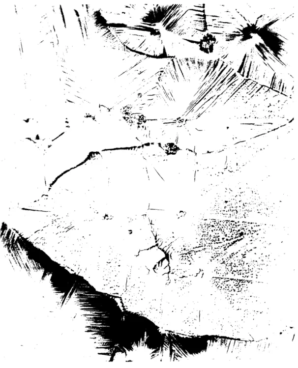
11 Typical ingot surfaces:
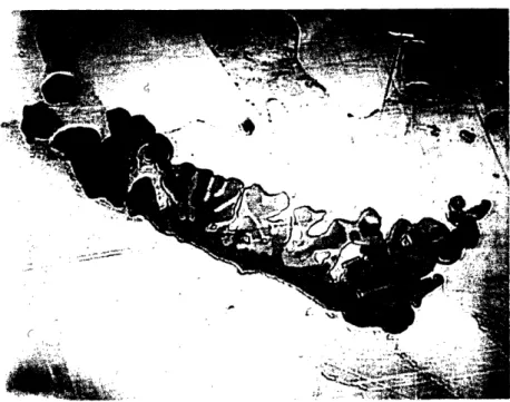
12 Surface of Fig 11 J(21.2 atomic pct C, 20.9 atomic pet Ti, bal Ni) at 450 X:
13 Particle in the nickel - titanium binary sample melted with a graphite electrode:
14 Arrangement of apparatus for heat-treating samples:
TABLES
I. Features of the System Ni-Ti-C: II. Data from Thermal Analysis:
9 10 16 17 18 22 :23 24 28 46 52 53 54 60 19 42
vii.
ACKNOWLEDGMENTS
The author wishes to express his sincere appreciation to
Professor John Wulff and Dr. James E. Cline for their continued
assistance, inspiring advice, and very helpful criticism in
patiently guiding this research. Among the many others who have
unselfishly contributed to the completion of this work, special thanks
are due to Malcolm Basche, Romeo G. Bourdeau, Richard H. Foss, Robert
L. Jones, James H. Johnston, William A. Moffatt, Robert M. Rodgers, and Phyllis M. Stratton. Financial support was provided by the Wright Air Development Center.
I. INTROIXJCT ION
In the search for new materials capable of resisting the
drastic service conditions of jet engine turbine blades, extensive
studies have been made of the "cermets", also called "ceramals", "metamics", or "metal ceramics", These are bodies composed of fine grains of an oxide or an interstitial compound "cementedw together
by a metal or alloy of iron group elements. Among such alloy
mix-tures, titanium carbide - nickel compositions have demonstrated
many advantages, such as good resistance to thermal shock and oxi-dation, superior strength - weight ratios, and the use of materials readily obtained by the United States.
Titanium carbide - nickel bodies are prepared, like other cemented carbides, by sintering or infiltrating pressed compacts at temperatures above the solidus of the alloy. To aid in under-standing the variables involved in sintering or infiltrating and their effects on the final properties, a limited study of the system nickel-titanium-carbon has been made. The equilibrium relationships in the vicinity of the solidus, together with the effects of cooling rate and contamination in modifying both the equilibrium and the
grain structure, provide a detailed picture of the roll of the
2.
II. PREVIOUS WORK
A. Phase Relationships in Cemented Titanium Carbide.
Although the manufacture and properties of titanium carbide cemented by nickel, cobalt, and various alloys have been described in detail, no previous investigation of the phase system has been made. Free graphite is frequently encountered in commercial alloys,
but gradient studiesI have shown that no intermediate phase exists between nickel and titanium carbide, which is usually termed "riC " .
Eutectic between carbide and metal: Trent, Carter and Bateman,2 in studying TiC - nickel cermets with small additions of Cr302, noted that liquid started to form between 1200 and 1300 Co Bourdeau3 reported that a plate-like eutectic structure containing
9 0,5 per cent TiC by weight resulted from slowly cooling ingots made from 10 per cent TIC - 90 per cent nickel powder mixtures, and that pieces cut from such a structure melted at 1300 + 10 C.
Solubilit of carbide in metal: Polikarpova4 reported that cobalt dissolves 7 to 10 per cent TiC by weight between 1150 and 1250 C, but Zarubin and Molkov5 could find no solubility in nickel by metallographic examination. Nickel has been reported to dissolve up to 20 per cent TaC, 12 per cent Mo2C, 8 per cent Cr302, and 15-30 per
cent WC by weight.5 - 8
Solubility gf metal in carbide: Work in Germany9 indicated that cobalt dissolves in TiC, and Kieffer has stated1 0 that solid solutions of group IV carbides with group VI carbides (WC dissolved in TiC, for example) can dissolve 3 to 5 per cent nickel or cobalt at
room temperature. However, Metcalfel l found "no evidence from either X-ray diffraction data or spectroscopic analysis of carbides extracted from sintered products to suggest that WC, TiC, or their solid solu-tion dissolves cobalt."
B. Binary System Nickel - Carbon.
The diagram compiled by Kihlgren and Eash 2 is probably cor-rect with respect to the eutectic composition (2.2 weight per cent
car-bon) and the solubility of carbon in nickel (0.65 weight per cent at
1318 C.) However, the eutectic temperature (1318 C) is based on early thermal analysis measurements which were subject to considerable error. Three groups of investigators1 3 - 1 5 cooled 20 to 25 gram hypoeutectic melts at 1 to 2 degrees C per second, and the eutectic arrests obtained varied between 1298 and 1325 C, due to supercooling and impurities. Kasets highest value of 1318 C1 5 was taken by the reviewers as the best eutectic temperature.
Better results have been recently obtained by Morrogh and Williams1 6 who solidified hypereutectic alloys made by melting pure nickel shot in graphite at cooling rates of about 16 degrees C per minute. Arrests at 1323 to 1326 C occurred for alloys which solidified with the "undercooled graphite" eutectic or, when treated with calcium silicide, with nodular graphite. Both types of structures should form below the true equilibrium eutectic. Coarse graphite structures, forming between 1310 and 1330 C, occurred after varying additions of sulfur, and increasing sulfur should lower the solidus. The authors show a good arrest at 1328 C for an alloy containing 0.3 per cent
4.
sulfur and forming coarse graphite on solidification; this value, rather than 1318 C, is the best present value for the eutectic. Most
errors in thermal analysis tend to yield low temperatures, and the early workers did not realize the effects of nucleation on the gra-phite solidification temperature.
Although an inflection in the liquidus at 2100 C occurs at
25 atomic per cent carbon,1 4 a solid carbide of nickel can be obtain-ed only by quenching superheatobtain-ed melts or by chemical reaction around 170 to 250 C 17-18 This hexagonal-close-packed, paramagnetic struc-ture dissolves carbon interstitially up to a maximum corresponding to the formula Ni3C. Upon heating in vacuum, it decomposes at 210 C
into a metallic interstitial phase of nickel supersaturated with
car-bon. This transition "Ni.4CU has a higher lattice parameter and a lower Curie point than the solid solution in equilibrium with
gra-phite .18
C. Binar System Nickel - Titanium.
Three stable intermetallics occur in this system:
(a) Ti2Ni, decomposing at 1015 C,1 9 has the complex cubic
structure isomorphous with the eta phase in the
wolfram-carbon-cobalt and similar systems. It has been reported to
dissolve oxygen to the composition Ti4Ni22 00.
(b) Ti, melting at 1240 C,19 has a brittle, cesium
chloride structure.21
(c) TiNi3, melting at 1378 C, is a fairly tough, closely-packed hexagonal Laves phase, having layers in the order
Only the region between titanium and TiNi3 has been accurately
determined using pure materials.l9 The nickel - TiNi3 region, of
greatest interest here, is shown by Skinner2 3 as determined by Vogel
and Wallbaum. 2 4 Their diagram is undoubtedly inaccurate, as it is
based on cooling curves, obtained at 1 to 1 degrees C per second, on 20-gram melts made from nickel wire" and 95 per cent pure titanium in pythagoras crucibles under argon. Their results indicate a eutectic at 1287 C and 16.2 weight per cent titanium, and a solubility in
nickel of 10.8 weight per cent titanium at 1287 C, 7 per cent at 1200
C, and 3 per cent at 850 C.
D. Binar System Titanium - Carbon.
The solubilities of carbon in alpha and beta titanium2 5 and
of titanium in "TiC" (about 22 to 26 atomic per cent between 1800 C and 900 C)2 5-2 7 are the only portions of this system which have been
accurately determined to date. Approximate measurements indicate that
the solidus varies from about 1800 C (peritectic with beta titanium)2 8
to a maximum near 3250 C.2 9 Hot pressing data indicates that the
TC-graphite eutectic lies between 1900 and 3000 C, probably about 2500 C.3 0
The only carbide, "TIC", is a face-centered-cubic-interstitial
structure (type B1), which has a very high modulus and good conductivity.
The interstitial lattice is apparently more completely filled at higher temperatures and lower pressures,3 1 but the stoichiometric composition in carbon (20.05 weight per cent) is difficult to achieve. The
car-bon solubility limit when in contact with amorphous carbon may be as high as 19.5 weight per cent, but the equilibrium with graphite is
6.
apparently lower.3 2
E. Effects of Oxygen and Nitrogen Contamination.
Since oxygen and nitrogen are usually present in commercial
TiC, their effects on the binary carbide are very important. Both elements readily displace carbon in the interstitial lattice,
lower-35-36
ing the parameter, the solidus, and the modulus.35 The solubili-ties increase with decreasing temperature and increasing pressure of the gas in equilibrium with the solid.3 1 -3 2 The carbide is oxidized in air at lower temperatures (1200 C), but nitriding takes place more
readily at the higher temperatures (1800 C.)3 1 Diffusion of nitrogen through the lattice is apparently quite slow.31 Although TiC, TiN, and TiO may form a continuous series of solutions at the higher
tem-peratures, a gap in the TiC - TiO system appears to exist at lower
temperatures in the vicinity of 8 weight per cent carbon.3 4 As the
ionic character of the bonding changes, the color of the phase may also change; TiC-rich solutions are uniformly light gray, but TiO may vary between yellow and black,3 7 and a pink compound in titanium
steels has been identified with TiN.3 8
Dissolved oxygen is particularly deleterious for cemented carbides; it inhibits wetting by a binder such as cobalt, forcing the use of higher sintering temperatures. At temperatures sufficiently above the solidus, solution and "recrystallization# of carbide through
the binder results in a copious evolution of CO, which leads to poro-sity in the center of the body.3 9
Hydrogen also dissolves interstitially in TiC,4 0 and this gas may decarburize the phase by a slight amount through the formation of
hydrocarbons, under the proper conditions of temperature and
3.
III. EI;Xfl NTAL
A. Preliminar Studies.
Due to the outstanding stability of TiC among the binary systems, a quasi-binary section possessing an invariant eutectic line between this phase and pure nickel was anticipated. Consequently, studies were first made with TiC - nickel powder mixtures.
Figure 1 shows the result of melting a pressed compact contain-ing 20 per cent of an 18,7 weight per cent carbon TiC on the original surface of a TiC-graphite block (arcceast at du Pont) in argon con-taining 0.1 per cent nitrogen. The eutectic structures, the prefer-ential solution of graphite, the "recrystallizationu of carbide
through the liquid, and the lack of wetting of a contaminated surface layer are evident. When the combination was tipped on its side and reheated, movement of the edge of the casting was observed at 1290 + 15 C.
Thermal analysis of nickel - TiC powder mixtures containing 10 and 13.7 per cent TiC in zirconia under argon was conducted at cool-ing rates of 14 to 26 degrees C per minute. Solidification occurred between measured temperatures of 1240 and 1300 C The initial melt-ing of a powder mixture took place 40 to 50 degrees higher, but good agreement was found between cooling curves and heating curves of pre-viously melted ingots. See Appendix A for details.
Since the thermal analysis ingots were severely contaminated with gases absorbed from the refractory and from the atmsophere, additional phases besides TiC, graphite, and alpha nickel were formed. Figure 2-A
compact and an arc cast TiC block after holding one-half hour at 1340 C and slowly cooling. Unetched. 50 X. Notice (from the bottom):
(a) Original block structure: carbide dendrites in a carbide - graphite eutectic;
(b) Diffusion region of graphite solution and growth of
carbide grains through the liquid;
(c) Undissolved interface and angle of contact between
the liquid and the block surface;
(d) Structure of the solidified liquid: flake graphite,
carbide eutectic, and alpha (nickel) dendrites; (e) Undissolved carbide grains floated to the top of the
10.
i
-V p4
r
r
.
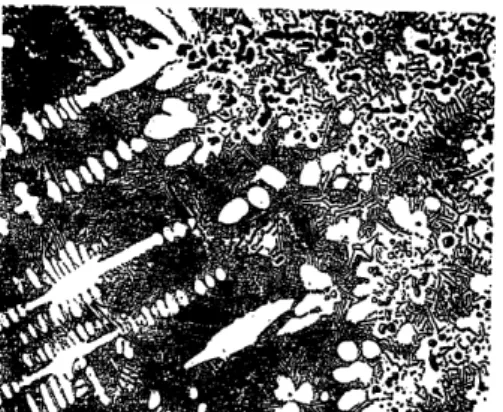
A - Partially dissolved carbide grain. 1000 I.
B - Eutectic structures at bottom of ingot. 500 1.
Fig 2 - Structures in the 13.7 weight pct TiC thermal analysis
ingot after melting and solidifying three times in zirconia under impure argon. Carapella's reagent.
w
shows dark gray phases, probably resulting from oxygen, associated
with lighter TiC and black graphite. (Note also the precipitate
from the inter-carbide alpha.) Figure 2-B shows not only the TiC
eutectic associated with graphite in the bottom of the ingot, bat a finer, softer, pinkish eutectic of another phase, which shows much
less tendency to develop the cubic symmetry of TiC on solidification.
(Margolin and Nielsen4 show identical eutectic structures, similarly associated, in a contaminated 10 per cent titanium - 90 per. cent nickel arc cast ingot.) In addition, the 19.6 per cent carbon TiC used in the mixtures contained some of the rose-colored grains
fre-quently encountered in conmereial carbide; these grains remained
undissolved, but TC precipitated upon them during solidification. Supplemented by other structural studies of melted powder mixtures, these preliminary results indicated. (a) the anticipated
quasi-binary probably did not exist; (b) oxygen and nitrogen could
form dark gray and rose-colored phases in the microstructure in
addi-tion to raising the liquidus (inhibiting wetting) and lowering te
solidus (indicated by the additional eutectico) Consequently, the
subsequent plan of work was to examine the whole nickel end of the ternary system by a procedure designed to eliminate contamination as much as possible.
B, Procedure.
1. Alo-Y Pre=aration:
Compositions were prepared from the following materials:
(a) blocks cut from a reject ingot of spectroscopic quality
I2.
by International Nickel Company); (b) spectroscopic carbon electrodes;
(c) titanium sponge prepared by du Pont.
In a few cases, mixtures of nickel powder (98.43 per cent nickel plus cobalt) and 19.6 per cent carbon TiC (prepared by Kennametal) were used.
Ingots were arc cast in a nickel-plated, water-cooled copper crucible with a graphite electrode in a closed helium atmosphere,
pre-purified through activated charcoal at -187 C and gettered prior
to melting each alloy by melting successively several buttons of sponge titanium. This procedure probably confined contamination to
that within the starting materials, although minute amounts of oxygen
and nitrogen could not be eliminated from the samples.
Each ingot was weighed, sectioned, and examined for hmo-geneity. Chips were machined from the sectioned surface of one-half
of each ingot of critical composition for analysis of carbon and tita-nium. (See Appendices B through F for the details of alloy
prepara-tion and chemical analysis.)
2. Heat Treatment:
Each ingot was cut and broken into six or eight wedges, which were placed in pre-reduced zirconia boats for treatment at different
temperatures. A zircon tube, heated by globars, constituted the fur-nace chamber. The helium atmosphere was pre-purified through calcium
at 650 C and gettered by titanium sponge placed in the chamber near the samples. The temperature directly above the samples was measured by a platinum - 10 per cent rhodium thermocouple protected by a
glazed porcelain sheath. The thermocouple was calibrated against
the melting point of gold and the freezing point of copper, and the temperatures of the samples were checked with those measured by melting wedges of the pure nickel and of electrical copper.
To determine the solidus, the samples were held at differ-ent temperatures for 20 to 60 minutes and quenched into water. Such times were more than sufficient to cause solution and coalescence.
of the as-cast carbide structure at temperatures near the solidus,
and the quench transformed any liquid present to an easily identified
eutectic structure. Temperature measurement and control was usually accurate to within 3 degrees C, and data for important compositions were re-checked.
The liquidus could not be obtained by this method, since some decarburization and oxidation occurred despite the efforts to purify the atmosphere. Where large amounts of alpha remained solid,
however, the decarburized rim at the sample surface was confined to
a narrow region, and incipient melting in the interior was not affec-ted.
In addition, the equilibrium with graphite was checked at 1240 and 1190 C by annealing alloys for 24 hours and 10 hours
respec-tively. These times were sufficient for the nucleation and growth of new graphite particles and for the coalescence of most of the
car-bide eutectic.
Appendices G and H give further details of the heat treat-ment procedure.
I4..
3. Examination:
Each treated sample was sectioned and mounted for micro-scopic examination. Polishing was conducted with diamond dust
(Diamet Hyprez) in kerosene on the back of photographic paper and on
"Miracloth". Carapella's reagent (acidified FeC13 in alcohol) was
used as the etch. Density, hardness, and volume percentages were measured in a few cases to supplement the structure data, and the
carbide phase in the microstructures was identified with TiC by the spectrometer pattern of a polished surface.
An approximation of the limits of the alpha phase was obtain-ed by a crude magnetic analysis. The Curie point of nickel (353 C) is decreased uniformly with increasing titanium to room temperature at about 10 atomic per cent titanium; 4 2 data by Kase1 5 and Bernier1 9 on
nickel supersaturated with carbon shows that carbon has a slightly less effect. While the odd shapes of the specimens and the decarbur-ized surfaces prevented accurate Curie point measurements, an
approxi-mation of the alpha composition in different specimens could be
obtained by immersing the specimens in a liquid bath, which was slowly heated or cooled, and determining the temperature range in which the
attraction of the specimens to an alnico magnet decreased to a very low value. While the precision of such a method is inherently low, a good check with the reported Curie point of pare nickel was obtained.
Carbide lattice parameters were compared by the powder me-thod, using a Phragmen camera with iron and copper radiation.
C. Results.
1. Tentative Diagram Nickel-Titanium-Carbon Above 120C: The quantitative information obtained is presented in terms of a projection onto a 1200 C basal plane (Figure 3) and three
vertical sections through the diagram (Figures 4 and 5), plotted on an atomic per cent scale. Table I summarizes the features that have been determined. Appendix D gives the exact alloy compositions.
Accuracy of the eutectic temperatures listed is probably within + 4 degrees C; the size of the blocks in Figures 4 and 5 is representative of the maximum error in each measurement, and these
figures are reproduced accurately to scale. The eutectic compositions
listed in Table I are based on the microstructures of nearby alloys, and these points are very approximate.
Alpha solvus data for compositions having more than 10 atomic per cent titanium could not be obtained, since the magnetic analysis
indicated that equilibrium with respect to TiNi3 was not achieved at
the lower temperatures. The remainder of the solvus was determined, however, using magnetic data from many compositions and the structures in the two alloys richest in nickel. The boundary at 1200 C thus
ob-tained was extrapolated to the nickel-titanium binary.
It is possible that residual oxygen and nitrogen in the
al-loys caused a shifting of the nickel-rich boundaries to slightly lower carbon contents than would occur in the true ternary system; however, the: agreement between the data for different compositions is good, and the colored contaminated phases were not observed in the ternary
16.
PFig 3 - Nickel-Titanium-Carbon diagram projected onto a basal plane at 1200 C (atomic per cent scale).
Circles indicate the compositions;
long-dash lines are on the liquidus;
Iase / '/ 1~11 / I I I I / I I I / I I I / / I I / I I / I I I 50/50 Cermet 30/70 C ermet 10/90 Cermet 0 o Ni, o ;r, q0-A 0A V ,Ti N ago. , 300 I
17.
Fig 4 - Vertical sections across the + TiC
field showing data obtained.
A; Section between 7 atomic per cent
carbon, 0 atomic per cent titanium, and 0 atomic per cent carbon, 16.4 atomic per cent titanium.
B: Section between 20 atomic per cent carbon, 0 atomic per cent titanium, and 0 atomic per cent carbon, 20 atomic per cent titanium.
Squares: two-phase fields;
Triangles: three-phase fields;
Relative amount of liquid indicated by proportion of black.
1220
1200
ATOMIC PER CENT TITANIUM
A
ATOMIC PER CENT. TITANIUM
B 1280 1260 1240 u U) w w 4 (D w a1 cr D w (L I 34U 1320 1300 u
I
(nw w a w I-:3 4 cr w a. 2 LL 1280 1260 1240 1220 1200 IRAN18.
Fig 5 - Vertical section between pure nickel and commercial TiC
(49.5 atomic per cent carbon). Circles: one-phase fields; Squares: two-phase fields;
Triangles: three-phase fields; Relative amount of liquid
0 0) ao 0 (D uJ LU Z L o I-o o o o o o o o o o o o o o o a 0 0 o 0 0 0 0 0 0 0 0 It 1) W) K) W) K 0) PI) CC CYc'. ID ' Ck CY 0CY D S33030 - 38nlivd3dN3i
c'L ~~O · rr\~~~~--· · oI cs r r40 H
0
r-'0 0 0
* (m' ('I;nl 0 U -to H O H - a,
Co 0 C- 4 ,_1 0 4 a, 2 0 H H H 01 0
H0 + -H 0-i
E., 'Hr-H- ,0 0 '0 * C cv\ * c0 r-I H H H C3 Hkp
o c C o * * 0 (N CY~ H C\ ( CV H H N N CMf8 0'(vH4 I0 + ' iEv ) 4) 4) 4) 4) 4) pq~ 19. 4)3 r-H .,E4 0 a4 3 4) -af 00 E U s4 A o 1 0 0a) ) h P 0) ID A m 0I
E-I H H E-i 0 0 a 4)' 0 4)~ Vs3 a 'H 0 t o ur rxro0 Isystematically. However, a 30 weight per cent nickel cermet sintered
in vacuum at 1350 C for 4 hours was leached electrolytically by the
method described by Chang,4 3 and the powder obtained was analyzed
chemically and by X-rays. The parameter observed was the same as that of the original TiC powder, and the analyzed nickel content was less than 0.05 per cent. An arc-cast composition containing about 0.8 per
cent nickel by weight showed considerable free alpha as well as
graph-ite in segregated areas of the microstructure, Thus, the solubility of nickel in TiC appears to be negligible.
The titanium-rich region of the system was not investigated,
but diffusion regions obtained in a few castings high in titanium showed that each of the binary intermetallics, Ti2Ni; TiNi, and TiNi3,
form two-phase fields with TiC on solidification. Thus, a ternary carbide phase cannot occur in TiC - nickel cermets, unless it forms
from the solid state at lower temperatures.
The diagram below 1200 C may have some significance for
cer-met manufacture since it was found that a vacuum-sintered cercer-met con-taining 30 weight per cent nickel had a Curie point very close to that
of the nickel powder used in its manufacture. The finely dispersed
structure revealed in the binder of commercial cermets at high magnifi-cations was not found in any of the high nickel alloys studied here;
but it is possible that stresses resulting from differential
contrac-tion between the carbide and alpha phases induce precipitacontrac-tion at very low temperatures during furnace cooling, thus resulting in a low alloy
21.
content in the binder. The precipitation in Figure 2-A may illustrate
such an effect.
2. Phase Shape and Mode of Formation:
The mechanical properties of cermets are influenced by
the size, shape, and distribution of the grains. Small, rounded, uni-formly distributed carbide grains have been associated with higher strengths than the large, angular grains resulting from sintering at
high temperatures. Large graphite plates in the microstructure have been blamed for weakness in some cases, although small amounts of fine-ly distributed graphite does not appear to cause much damage.2 Thus, information regarding the nucleation and growth of the phases on cool-ing from the sintercool-ing temperature is just as important as the equili-brium relationships.
Figures 6, 7, and 8 illustrate the most informative micro. structures encountered. The pictures were taken of etched samples
un-der polarized light. Together, they provide a picture of the grain
formation under the conditions of non-equilibrium solidification which may be encountered in commercial sintering practice.
Primary TigC, solidified rapidly from large amounts of liquid, always develops sharp crystals of cubic symmetry (Figure 7 A, B, and E). The corners can be rounded by solution and reprecipitation through
solid alpha by short anneals within 5 to 10 degrees of the solidus (Figure 8 A, and E). High carbide compositions, in which solidifica-tion occurs at higher temperatures and is accompanied by a greater
t . A. ' . 4 I/ I .
:,%A
·s? -.?. ,
"-C(.o,.o
* ; r * . Ote "
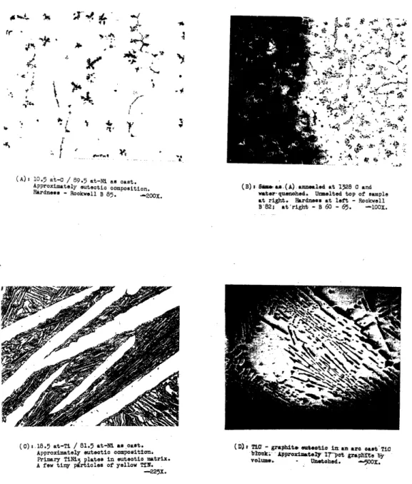
.v. I' ' r r r;o. , *t o ,, : :' : '~ ~ : . ' t .(A): 10.5 at-0 / 89.5 at-Ni as cast. Approximately utectic composition.
Hardness - Rockwell B 85. -200X. (B) l Sfm. a(A)anuealed water-quenched. Unmelted t 128 a andtop of sample at right. Hardness at left - Rockwell
B'82; at'right - B 60 - 65. -iOOX.
(0) 1.18.5 at-Ti / 81.5 at-Ni as cast. Approximately euteotic composition. (D)t 'T0 bOk;- -graphite uteatei i am arc cast TiC
-Approximately- r17-pt grapirte y
Primary TiNi3plates in euteotic matrix. volume, Unetohed. 5O00ZX
A few tiny particles of yellow TN. °
-225X.
Fig 6 - Important binary microstructures (reduced one-half)
5
A,
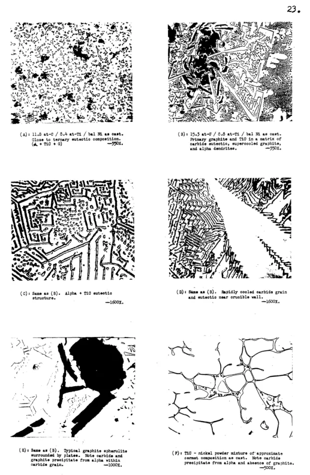
. r -i .. 1 I __(A): 11.8 at-C / 8.4 at-Ti / bal Ni as cast. Close to ternary eutectic compoition.
(~ + TiC + G) -3x.
(C) s Same as (B). Alpha + Ti euteotic structure.
-1600X.
(B): 15.3 at- / 8.8 at-Ti / bal Ni as cast.
Primary graphite and TiO in a matrix of
carbide euteotic, supercooled graphite, and alpha dendrites. -50x.
(D): Sime as (B). Rapidly cooled carbide grain and euteotio near crucible wall.
-1600X.
-7,
I )·
//
(E) ame as (B). Typical graphite spherulite
surrounded by plate*. Note carbide and
graphite precipitate from alpha within
carbide grain. -10OX.
(F) TiC - nickel powder mixture of approximate cermet composition as cast. Note carbide precipitate from alpha and absence of graphite.
-- 0oX.
Fig 7 - Iaportnt a-cast microstructures (reduced one-half) 23.
,' '
(A) 5.6 atkC / 13.3 at-Ti / bal Ni annealed at 1305 C.
Olose to quasi-binary euteotic oompoition. Solution and coalesooene of euteotic tructure.. ( + TiC). --. 5ox.
(B) Same as, (A) anneale a 1308 0 and water quenched.
Note mudiaselted carbide floating to top of sample
at right and selidifioation of liq~uid a alpha dndrite. anis euteetio. (L.,+TiO). --250.
r K
:'re
r! 2
( C) 6.0 at-C / 2.9 at-Ti / bL Ni nnealed at 129 C
and water quenched. Liquid has solidified as
supercooled graphite and anisotropic carbide
euteeti. (d + G L). --0OX.
3 ;
(D) 2.6 at-0 and / 14.9 t-Ti / bal Ni anneale at 1296 0
water quemnhed. Liquid ha- solidified as
TiNMT and anisotropic carbide euteotic.
'; + TiO 4 L). -300X.
(3) 2.8 at-C / 17.8 t-Ti / bal Ni annealed at 1284 C
and water quenched. Sall plates of TiNi, embedded in alpha dendrites and coalecoed Ti.
(& + TiC , TiNi). -5C30 .
(F) 4.0 at-o / 16.6 at-Ti / bal N annealed at 1280 C.
Decarburized and detitanized rim due to unusually
impure atmosphere; original ( + TiO) structure at left, oxide at right. -300X.
Fig 8 - Important annealed microstructures (reduced one-half) , .,
.. .
I. .5
- 'J
25.
(Figures 6 D and 7 F). Contaminated microstructures (not shown)
indicate that TiC is nucleated by the colored coygen-and
nitrogen-rich phases, and that more of a tendency to develop rounded grains
exists when these elements are in solution.
The first
pimary graphite
to solidify frequently was speru-litic in structure, but surrounding regions formed plate graphite anfurther solidification (Figure 7 B and E.) Although graphite - TiC
interfaces frequently occurred, no predominating tendency for TC to
nucleate graphite from the liquid could be noticed. Secondary
graph-ite in the TiC-graphgraph-ite eutectic is plate-like in nature (Figure 6 D.).
TiNi3, the only intermetallic which could be involved in
ter-nary cermets, occurs as large plates, when formed from either the liquid (Figures 6 C and 8 E) or solid alpha (Figure 8 F). Since it did not form readily from the solid upon annealing at low temperatures, even after moderate cold work, the nucleation rate must be quite low
at the lower temperatures.
The alba binder is the last phase to solidify in commercial
compositions. If the cooling rate is sufficiently rapid, this phase
can become supersaturated in both carbon (Figure 6 A and B) and tita-nium (indicated by a lower Curie point in cast binary samples than in those quenched from the solidus). The solubility in alpha of TiC plus
graphite is displaced to slightly higher carbon contents by rapid cooling, since less graphite was found in the structure formed from the liquid in compositions cast or water-quenched than in the same alloys annealed at the solidus.
Although primary TiC tends to nucleate alpha during solidifi-cation (Figure 7 B and 8 B), the nucleation of TiC is sufficiently
ure 7 C) to form at some low temperature, possibly characteristic of spontaneous carbide nucleation. The eutectic composition is
suppres-sed to higher carbide contents than the equilibrium composition, re-sulting in primary alpha dendrites in the microstructure (Figure 8 B
and 9 B). The size and separation of the eutectic plates decreases with increasing cooling rates and with decreasing carbon content across the two-phase field (alpha plus TiC), The eutectic structure did not occur where the solidifying binder was largely surrounded by primary carbide (Figure 7 E and F) and in one high-nickel composition (Figure 7 A), in which solidification was confined to a narrower range of
tem-perature.
A eutectic structure of another carbide phase formed from
water-quenched liquid of two compositions with carbon - titanium ratios far from that of TiC (Figure 8 C and D). This structure, finer and
softer than the TiC eutectic, shows a definite anisotropy under
polar-ized light, whereas TiC and the contaminated pink" eutectic do not. A non-equilibrium structure, this carbide may be related to Ni3C. Such
a carbide was not found in the binary compositions, although the pre-sence in the cast eutectic alloy (Figure 6 A and B) of supersaturated
i4Cl and graphite dendrites resembling temper carbon suggest its
transient existance.
27.
IV. DISCUSSION AND CONCLUS IO15
A. The Eauilibrim Diatrm.
The portion of the ternary system studied here is of a simple
type, possessing a "quasi-binary eutectic# between the alpha and car-bide phases. However, since the substitutional solubility of titanium
in nickel is aboat four times the interstitial solubility for carbon,
this quasi-binary" is pulled away from the section between the
com-ponent and the compound. The other ternary systems between cobalt or
nickel and the carbides of transition elements of groups IV and V
pro-bably show this same feature, since the binaries are similar. It may be a general feature of all carbide-metal cermets that liquid and solid
binder are at equilibrium over a range of temperatures, in contrast to the idea of a "eutecticw which has been presented in the past.
The useful region of the ternary system is summarized in the
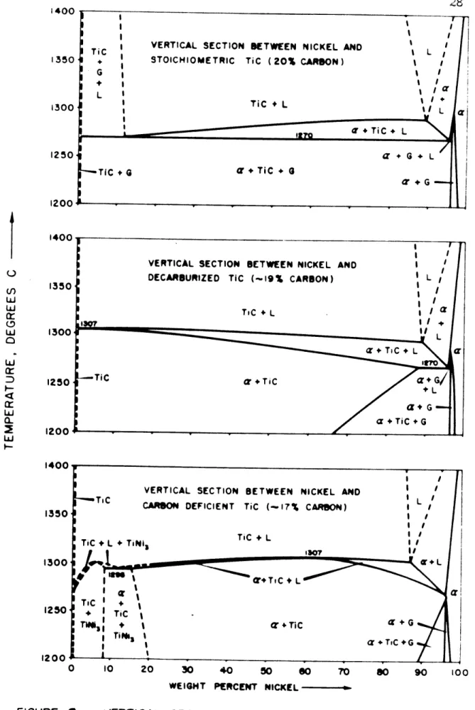
weight per cent vertical sections of Figure 9, which cover the range of compositions which should be encountered in commercial cermets. Since
uncontaminated titanium carbide does not appear to dissolve the
stoi-chiometric amount of carbon, graphite is included throughout the top section of Figure 9. This section might also cmesspond to cermets pre-pared from a carbide 'of lower carbon content, since the oxygen and
nitro-gen impurities present would tend to displace carbon from interstitial solution in the form of graphite. If sintering is carried out in a high
vacuum, however, the formation and removal of carbon monoxide from the
compact will cause some decarburization and free graphite will not form on solidification. The central section of Figure 9 then might correspond
STOICHIOMETRIC TiC (20O CARON) TiC L % I ' I
I/:li
tl L Iq I' L--TICG a+TiC + I r G I 0 10 20 30 40 50 0O 70 s0 90 100WEIGHT PERCENT NICKEL
FIGURE 9 VERTICAL SECTIONS THROUGH TERNARY N-TI-C DIAGRAM
AT AND NEAR THE TiC-Ni PLANE.
I,+ G I L
IL
1350 1300 1250 1200 l-VU 1350 1300 t LJ oO W LLJ:
-a- Q-W 1250 1200 1350 1300 1250 1200 ! I I I I I I II I "U + TiC + L iAAA i ~ A :---,.,.. ~I i i29.
to vacuum-sintered cermets. Note that it is possible to sinter
com-mercial compositions (20 to 60 per cent nickel) in the presence of both liquid and solid binder, but that the width of temperature range for such a treatment decreases with either decreasing nickel or de-creasing carbon in the alloy.
In small amounts, the effect of the impurities and addition agents normally found in commercial cermets may be expressed with the aid of the equilibrium diagram. Oxygen and nitrogen can effectively increase the carbon content of a composition by displacing carbon from interstitial solution in both alpha and TiC. Transition metal impuri-ties or additions shift a composition towards some point on the nickel-titanium binary, the position of that point depending on the valence
of the metal. Most impurities or addition elements probably lower the solidus surface of the system and increase the range of the three-phase
field (alpha plus carbide plus liquid), carbon being constant.
B. Binder Phase Relationships during Sinterina.
The phase changes that take place during sintering can best be reviewed by the history of a cermet body.
When the pressed compact is first heated, liquid will be in equilibrium at 1270 C due to the free carbon in the carbide powder. However, the presence of oxide films around the carbide grains will
in-hibit solid state diffusion, and liquification may be suppressed to a
higher temperature, perhaps in the range of the nickel-graphite eutectic. All of the binder will be liquid at equilibrium above the range 1290 to 1305 C, In this temperature region, or slightly above it, carbon and
oxygen in the sample will react to produce carbon monoxide, which can form large bubbles trapped within the compact if sintering is not
carried out in a sufficiently high vacuum.
At a sintering temperature of 1350 C, about one-third of the volume of a 40 weight per cent nickel cermet should be liquid, assuming
a liquid density of 7.9 grams per cubic centimeter. While the total
amount of liquid present does not increase rapidly with increasing
temperature (the liquidus for this composition is probably above 2500 C),
an increased rate of carbide grain growth, by solution and redeposition
through the liquid, will result in a larger volume of liquid around
each carbide grain at the higher sintering temperatures. Rapid cooling from such temperatures causes larger, more angular grains to form in
the cermet microstructure. If the temperature is kept sufficiently
low, on the other hand, solution and redeposition will occur without much total grain growth, and small, rounded or kidney-shaped grains
will result. The best sintering temperature and time will be a balance between that required to remove all of the carbon monoxide produced by solution of the impure carbide, and that necessary to retain a small,
uniform grain size.
Upon cooling from the sintering temperature, carbide will de-posit on all primary grains, even those which might not have dissolved
at all during sintering due to the presence of contaminated surface
layers. The alpha phase will solidify over a small range of
tempera-tures, while the eutectic carbide continues to deposit on the primary.
31.
the liquid will increase in carbon and decreases in titanium with de. creasing temperatures. Although graphite plates would tend to
preci-pitate from the last liquid to solidify, the rapid rate of solid
diffusion near the solidus, together with the tendency for the binder to become supersaturated in carbon upon rapid cooling, should
elimi-nate such precipitation if the carbon and oxygen contents have been sufficiently reduced by high vacuum sintering. The higher the nickel content of a cermet, the greater will be its tendency to form graphite, as illustrated in Figure 9.
At very low temperatures, the stresses in the binder set up-due to the difference in contraction between the carbide and alpha
phases may induce precipitation of finely distributed carbide, graphite,
or some transition structure, leaving behind the pure and ductile binder
V. s omRY
The nickel-rich portion of the system nickel-titanium-carbon
has been tentatively determined above 1200 C by metallographic examina-tion of samples quenched from different temperatures, supplemented by thermal analysis and magnetic, X-ray and density measurements. The
equilibrium surfaces thus obtained, together with modifications of the phase boundaries and grain structure due to non-equilibrium
soli-dification and oygen and nitrogen contamination, allow a detailed
discussion of the role of the binder in sintering titanium carbide -nickel cermets.
33.
VI. BIBL I.A1
1. W. J. Engel: Bonding Investigation of Titanium Carbide With Various Elements, AA Technical Note 2187, Sept. 1950.
2. E. M. Trent, A. Carter, J. Bateman: High Temperature Alloys Based on Titanium Carbide, Metalluraia (1950) 42, pp 111 - 115. 3. R. G. Bourdeau: Titanium Carbide Cemented With Nickel, SB
Thesis, Mechanical Engineering Dept., M.I.T., 1951.
4. Polikarpova: Extract of paper submitted to obtain degree of Certified Engineer, MU, 1937, I-Ray Laboratory, Elektrozavode. Quoted by G. A. Meerson, et al in reference 39; Brutcher
Transla-tion 162, p 5.
5. N. M. Zarubin and L. P. Molkov: Investigations of Alloys Produced According to Ceramic Methods, Vestnik Metallotrov (1935) 1, pp
93 - 98; Chemical bsact 31, 6170.
6. N. M. Zarubin and R. A. Trubnikov: On the Study of the State Diagram of the Systems Carbide-Chromium-Cobalt and
Carbide-Chromium-Nickel, Red Metali (1935) No. 2, p 38.
7. S. Takeda: A Metallographic Study of the Action of the Cementing Materials for Cemented Tungsten Carbide, Science BReorts T ohkg
Ierial Universit, First Series, onda niversar Vlume (1936),
p. 864.
8. P. Rautala: The Wolfram-Carbon-Cobalt System, ScD Thesis, Metallurgy Department, M.I.T., 1951.
9. ,: Determination of the Solid Solubility of Cobalt and Iron in Refractory Carbides, Studiengesellschaft Hartmetall, eb, 1941; US Dept. of Ccamerce B 10 2 (BOT FD 3861/47); also abstracted in
Metal PoWder Renort, May, 1948, p 142.
10. R. Kieffer: Theoretical Aspects of Sintering of Carbides, The
Wph si¢ f PoMwder Metallur (edited by W. . Kington), McGraw-Hill, 1951, pp 278, - 291.
11. A. G. Metcalfe: The Mutual Solid Solubility of WC and TiC, Jl
Inst of Metals (1947) 2, p 591.
12. T. E. ihlgren and J. T. Eash: Carbon-Nickel, ASM Metals Handbook,
American Society for Metals, 1948, p 1183.
13. V. K. Kriedrich and A. Leroux: Information on the Melting-Point Diagram of Nickel-Carbon Alloys, Metallutrie (1910) 7, pp 10 - 13.
14. O. Ruff and W. Bornann: Studies in-the Range of Higher
Temperatures VI: Nickel and Carbon, Zeitschrift fn Anoranisch
hbenie (1914) 88, pp 386 - 396.
15. T. Kase: On the Equilibrium Diagram of the Iron-Carbon-Nickel
System, Sience Reorts of the Tohoklu Imperial University (1925)
1, pp 174 - 217.
16. H. Morrogh and W. J. Williams: Graphite Formation in Cast Irons
and in Nickel-Carbon and Cobalt-Carbon Alloys, T Iron and
Steel Ist (1947) ;1f, pp 322 - 369.
17. J. E. Hofer, E. M. Cohn, and W. C. Peebles: Isothermal
Decomposi-tion of Nickel Carbide, Jrl Physical and Colloid Cheitrs (1950)
.5A, pp 1161 - 1169.
18. R. Bernier: Thermomagnetic Studies of the Carbides of Iron and
Nickel, annles de Chimie (Jan-Feb, 1951) 6, pp 104 - 161.
19. J. P. Nielsen (New York University): Nickel-Titanium diagram
pre-sented at the Fourth Conference on Titanium, Wright-Patterson Air
Field, Jan. 24 - 25, 1952.
20. W. Rostoker: Observations on the Occurrence of Ti2Z Phases,
Trans AIW, aJ f ta (1952) A, pp 209 - 210.
21. V. F. Laves and H. J. Wallbaum: The Crystal Chemistry of Titanium
Alloys, Naturwisnshafte (1939) 27, pp 674 - 675.
22. V. .Laves and H. J. Wallbaum: The Crystal Structure of Ni Ti and Si2Ti (Two New Types), Zeitschrift S Kritallograaie, (1939)
01, p 78.
23. E. N. Skinner: Nickel-Titanium, S Metals Handbok, American Society for Metals, 1948, p 1235.
24. R. ogel nd H. J. Wallbaum: The System Iron-Nickel-Ni Ti-Fe2Ti,
bArchive fr da Esenhuttenwesen (1938) 12, pp 299 - 303. 25. J. P. Nielsen: Titanium-Carbon and Titanium-Nitrogen Alloys,
Final Report for the period 1 Dec 1949 to 30 Sept 1950, WAL 401/14
-12, Contract DA 30-069RD 6, Nov 30, 1950.
26. J. G. Mclillin: The Constitution of Titanium-Tantalum-Carbon Alloys, Metallurgy Dept, MIT, 1952; also thesis by D. V. Ragone, B, 1951, and G. W. P. Rengstorff, SM, 1948.
27. P. Ehrlich: On the Binary Systems of Titanium with the Elements Nitrogen, Carbon, Boron, and Beryllium, Zeitschrift r Anorganisch Chemie (1949) 259, pp 22-41; Brutcher Translations 298 and 222.
35.
28. J. P. Nielsen (New York University): personal communication to J. G. McMullin (MIT), February, 1952.
29. R. Kieffer and F. Kolbl: International Powder Metallurgy Conference, Graz, Austria, July 12-17, 1948, Ref No 28; quoted by C. G. Goetzel
in Treatise J Powder MetalurV, V I, New York, 1950, p 83.
30. F. W. Glaser and W. Ivanick: Sintered Titanium Carbide, Trans ADME,
&I o1 Metals (1952) , pp 387-390; See also patents by H. R. Montgomery: US 2496,671, and C. C. Laughton and E. Wainer: US 2,491,410.
31. A. N. Zelikman and N. N. Gorovits: Study of Interaction between Nitrogen and Titanium Carbide, Zhurnal Prikladnoi Khimii (1950)
a, pp 689-695; Brutcher Translatio 2593.
32. G. A. Meerson and Y. M. Lipkes: Investigation of the Conditions of Titanium Carburization III and IV, Zhaal Priklanoi Khimii
(1945) j4, pp 24-34 and 251-258; Brutcher Translations 928 and j. 33. K. Becker: H h Melting Hardmetals and their Technical Manfacture,
Berlin, 1935, p 57.
34. H. Krainer: Pysical Studies of Titanium Carbide and of Cemented Carbide Compositions Containing Titanium Carbide, Archive ffr das Eisenhuttenwesen (1950) , pp 123-127; Brutcher Translation 260. 35. C. G. Goetzel: Treatise on Powder Metalluo Vol II,
,
New York,1950, p 81.
36. P. Duwez and F. Odell: Phase Relationships in the Binary Systems of Nitrides and Carbides of Zirconium, Columbium, Titanium, and
Vanadium, Jl1 Electrochemical Society (1950) 97, p 299.
37. Armour Research Foundation: Tta Phase Dia raM, Report No. 9,
for Air Materiel Command, Wright-Patterson Air Force Base,
June 11, 1951, p 13.
38. I. S. Gaev: Diffusion of Titanium and Dissociation of Titanium Compounds, Metallr (1934) 2, pp 19-33; Bfrtcher Translation 4.
39. G. A. Meerson, G. L. Zverev, and B. Y. Osinovskaya: Investigation of Behavior of Titanium Carbide in Cemented Carbide Alloys,
_w1~41 Prikadnoi Khimii (1940) 3, pp 66-75; Brutcher Translation
1642.
40. F. H. Pollard and P. Woodward: The Stability and Chemical Reactivity of TiN and TiC, Trans o ft Farada Society (1950) , pp 190-199.
Division, New York University, Fig 9, plate VII.
42. R. M. Bozorth: Ferronanetism, Van Nostrand, 1951, p 325.
43. L. C. Cang: Discussion on the Isolation of Carbides from High Speed Steel, by D. J. Blickwede and M., Cohen, Trans AIME (1950) 188, p 1061.
37.
VII. SUGGESTIONS FOR FURTHER RESEARCH
Future work on this subject which might be the most profi-table may be along the following lines:
Nickl-rich Dortion of the diagram: An accurate study of the alpha solvus surface, perhaps accompanied by an identification of the binder precipitate in cermets, could be made by preparing high purity solid solution compositions, completely free of oxygen and nitrogen, and obtaining accurate Curie point measurements and lattice parameters, after working and annealing samples down to very low temperatures. The solidus surface of the system, including the two binary eutectics, may also be modified by more accurate work using iodide titanium and vacuum-melted nickel in preparing
composi-tions,
Carbide-rich ortion of the diagram: An accurate
determina-tion of the TiC solidus and the TiC - graphite solvus might be ob-tained by arc casting high-parity TiC and annealing samples either by
resistance or by radiation from a tungsten shield prior to quenching
and examination. The solubility of nickel in TiC might be obtained by careful leaching of completely recrystallized carbide grains from fine-grained compacts, and analyzing the carbide chemically and by X-rays, The effects of oxygen and nitrogen on the equilibrium
sur-faces and physical properties of the TC phase should be of such
practical interest, that these effects will undoubtedly
be subjects
Casting cermets: The mamufacture of pare carbides and cermet compositions by arc casting and subsequent heat treatment should be studied, since such a method provides a means of obtain-ing a completely dense material with a minimum of effort. As shown in Figure 7 F, kidney-shaped grains can be produced in cermet compositions by arc casting. The principal problems to be solved
in such a process are: control of composition, control of grain
size, prevention of cracking due to thermal shock on cooling, sub-sequent shaping of the ingot, and the very high power requirements in casting. Casting carbides and cernets is probably impossible
in any refractory container, due to oygen obsorption into the alloy, but graphite molds may be usefal if the inevitable free gra-phite in the microstructure can be rendered harmless.
390
VIII. APPENDIX
A. Therl Analysis
1. Procedure:
The principal experiments were carried out in the apparatus described by Zillman.* Pressed powder compacts were
packed into a zirconia crucible, 1-1/4 inches inside diameter by
2-7/8 inches deep, around a zirconia shield, j inch outside
dia-meter, 3/8 inch inside diadia-meter, and 2 inches deep. The crucible was placed inside a graphite seeve, which was heated by induction
from a copper coil, about 6 inches in diameter and 4 inches high; a longer coil would have produced a more uniform temperature in the sample, but power limitations prevented such a modification. The graphite sleeve was surrounded by alundm-plated and coarse
sirconia chips, packed into the water-cooled vycore cylinder
(closed at one end), which was used as the furnace chamber. An atmosphere of argon, partially purified by passing
through titanium sponge at about 600 C, was supplied by evacuating
the chamber with a mechanical pmp, and then letting in the gas until a slight positive pressure was achieved. The argon contained about .Oo1 per cent nitrogen, which was not completely removed, and caygen was undoubtedly released by the zirconia refractory, which blackened during use.
The temperature was measured by a platinum - 10 per cent
* R. W. Zillman, Se.D. Thesis, Metallurgy Department, M.I.T., 1950.
-rhodium thermocouple, fitted into an alundum insulator ground to
fit inside a 1/4 inch outside diameter clear silica tube. The
tube was inserted into the zirconia shield from a rubber seal at
the top of the furnace assembly. Whenever the thermocouple wires were not completely protected from the furance atmosphere, the thermocouple always broke during service. An ice water cold Junc-tion was used, and temperatures were recorded every 10 or 20 seconds by reading the millivoltages on a Brown potentiometer.
Power was supplied by a low frequency Tocco induction unit.
All attempts to use high frequency produced induced current in the thermocouple. No measurable effect on the temperature measurement resulted from using the Tocco.
The procedure followed was to heat the sample to 1400
-1500 C under a setting of about 6 K, and then reducing the setting to about 2 K. The temperature-time curve resulting was straight and linear through the liquid or solid regions, until a temperature
characteristic of the final setting was reached, at which a leveling-off occurred. Solidification usually occurred over a period of 10 to 15 minutes, and since the region of the curve corresponding to this period was also straight, an apprcximation of the limits of re-gion of solidification was obtained by the intersections of the straight-line portions of the curve.
An attempt was made to utilize a smaller globar furnace,
in which the cooling rate could be controlled over a wider range, but the constant temperature region was not sufficiently great in
41.
2. Resut.
The data obtained is summarized in Table I . Note that there is good agreement between the cooling curves and heating curves made on previously melted ingots in the larger assembly, but that the initial melting of the powder miixtures took place at a higher tempera-ture range. Kennmetal TiC was used for the 13.7 and 10 per cent samples, and a poorer grade was used in the 19.0 per cent rn. Sugar
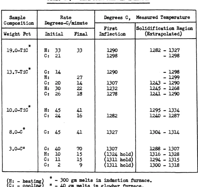
Table I. - DATA FROM THERMAL ANALYSIS
Il I I I I I
-H: - heating)
0:
- cooling) -- 40 gm melts in glowbar furnace.300 gm melts in induction furnace.Sample Rate Degrees C, Measured Temperature Composition Degrees-C/minute
First Solidification Region
Weight Pct Initial Final Inflection (Extrapolated)
19.0-TiC H: 33 33 1290 1282 - 1327 C: 21 1298 - 1298 13.7-TiC C: 14 1290 - 1298 H: 27 - 1299 C: 20 14 1307 123 - 1290 H: 30 22 1232 1245 - 1268 C: 26 18 1278 1241 - 1290 10.0-TiC H: 45 41 1295 - 1334 C: 24 16 1282 1240 - 1287 8.0-C C: 45 41 1327 1304 - 1314 3.0-C" C: 40 70 1307 1288 - 1307 H: 10 15 (1324 hold) 1316 - 1328 C: 11 15 (1311 hold) 1294 - 1315 C: 2 9 (1311 hold) 1300 - 1318
43.
B, Description of Startinm Materials. 1. Nickel:
a. Scrap ingot No. 19677 from International Nickel Company.
(1) Quantitative analysis: Weiht Pet
Ni + Co : 99.96
Si : 0.003
C:
0.014
(2) Svectroscopic ag:sis:
Co : slight trace
Al, Cu, Fe, Mg, Si : very slight trace B, Ca : less than very slight trace b. Nickel powder lot No. 497-S from Metals Disintegrating
Company.
Quantitative analysis: Weight Pct
Ni: 97.65 Co: 0.78 Fe: 0.52 Ca: 0.15 Si: 0.10 Remainder: 0.80 2. Carbon:
Cenco spectrographic electrodes, certified grade.
Sec trosconic aalys8is:
Cu, Fe, Mg: very slight trace
3. Titanium:
Vacuum-distilled sponge from du Pont.
4. Titarzim Carbide:
a., TiC from Norton Abrasives Co.
(1) Quantitative Analsis (98.8 pet pre): Ti :
C Total: C free :
C combined (by difference):
Si :
(2) SrectroscoDic AnalRsi:
Si,
, Fe:
Cr, A1, Ca, Cu, K, Mg, Ni, P, Rb,
Pb, Sb, Sn, V, Zn, Ag:
TiC from Kenrametal Incorporated.
(1) Quantitative Analysis (98.3 pet pure): Ti :
C total: C free:
C combined (by difference): (2) Soectroco Dic nalysis:
C_, V, Fe: T1i:
_E, Ag, A1, Ca, Cu, Mg, Ni, P,
Rb, Sb, Si, Sn, W, Z: Weight Pct 80.30 (80.16) 18.68 (18.71) 0.19 18.49 ( 0.09) 0.1 - 0.001 pct 0.01 pt or less 79.22 19.66 0.60 19.06 1.0 - 0.01 pct 0.1 - 0.001 pot 0.01 pet or less b.
45.
C. Arc Melting Equipment and Procedure. 1. -Eguiment:
Figure 10 illustrates the melting chamber used in making
most of the alloys. Originally constructed and described by J. H. Johnston,* the apparatus was modified slightly for the present
experiments.
Similar in design to the copper crucible arc furnace used in casting titanium-rich alloys, this equipment had several basic
features:
a. Crucible: A 1/4 inch thick electrical copper plate, containing three cupped indentations, was given a light nickel plate
and bolted over a water circulating chamber.
b. Electrode: A 3/16 inch spectroscopic carbon electrode mounted in a chuck at the base of a water-cooled copper column was used for low melting compositions; a large electrode ground from a 1-inch rod of Acheson graphite (shown at the right in Figure 9) was
necessary for high carbide compsitions.
c. Shield: A radiation shield of nickel sheet (shown at
the left in Figure 9) was placed around the crucible during melting
to protect the walls of the chamber from spattered metal.
d. Chamber: an 8-inch diameter pyrex cylinder, ground on both ends, was clamped between rubber gaskets (lubricated with
sili-cone grease) mounted in brass plates at the top and bottom of the chamber.
* J. H. Johnston, S.M. Thesis, Metallurgy Department, M.I.T., 1951.
I
. t Fig. 10 - Are melting chamber.
iB r, ;I :' I i
47.
e. Wiper: A strip of silicone rubber was mounted on a
steel rod and moved vertically along the inside surface of the cylinder to remove the sprayed metal dust which obscurred vision during melting.
f. Seals: The electrode column and wiper rod moved
ver-tically through lubricated rubber packing glands; the gland for the
electrode was mounted on a silphon bellows to allow lateral electrode movement. Leakage through the glands while the chamber was under vacuum was very slight, but to eliminate this source of contamination, an evacuated seal around the wiper rod and an evacuated rubber sleeve around the electrode column and silphon bellows were added. The gripping action of the evacuated sleeve also prevented excessive
strain on the bellows due to pressure increases in the chamber during
melting.
g. Vacuum: A mechanical pump capable of attaining less than 1 mm. mercury pressure was used to evacuate the chamber and
(separately) the sleeves. A mercury manometer was connected directly
to the chamber.
h. Atmosphere: Heliumat 1 or 2 centimeters mercury posi-tive pressure, was passed through a U-tube at -37 C, a vycore tube containing calcium turnings (resting on nickel sheet) at 650 C, and a trap containing activated charcoal at -187 C before entering the
chamber.
2. Procedure:
Intended to eliminate all atmospheric contamination of the samples during melting, a typical sequence of operations follows:
a. Charging: The weighed amounts of titanium sponge and small pieces of 3/16 inch carbon electrode were placed in the bottom of the largest indentation in the plate, and the one or two blocks of nickel used in the charge were placed on top. The two small in-dentations in the plate were filled with titanium sponge.
b. Preparation: The chamber was assembled, the cylinder carefully fitted between the gaskets, and the chamber alone evacuated. The top plate was clamped tightly onto the cylinder. Helium was
flushed through the purifying train and chamber. The charcoal trap was closed off from the rest of the purifying train, which was kept under a positive pressure, and the charcoal (and chamber) were
eva-cuated while the charcoal was heated at 450 C for one hour. Then the charcoal was cooled slowly to -187 C, sealed from the chamber, and helium was allowed to enter the trap. A stopcock between the
chamber and vacuum line was then closed, and the seals at the top of
the chamber were evacuated. Helium was allowed to enter the chamber from the purifying train over a period of about twenty minutes, until a slight positive pressure was achieved in the chamber. Then the chamber was closed off from the trap, and the water to the electrode
column and crucible was turned on.
c. Gettering: The closed atmosphere to be used for melt-ing the sample was gettered by meltmelt-ing successively several small buttons from the sponge in the small indentations. The titanium was