The BoPen: A Tangible Pointer Tracked in Six
Degrees of Freedom
by
Daniel Matthew Taub
S.B., EECS, M.I.T., 2006
Submitted to the Department of Electrical Engineering and Computer
Science
in partial fulfillment of the requirements for the degree of
Master of Engineering in Electrical Engineering and Computer Science
at the
MASSACHUSETTS INSTITUTE OF TECHNOLOGY
September 2009
ARCHIVES
@
Massachusetts Institute of Technology 2009. All rights reserved.
Author ...
...
Department of Electrical Engineering and Computer Science
August 21, 2009
C ertified by ... t . ...Ramesh Raskar
Associate Professor
Thesis Supervisor
Accepted by.
. . . . . .. . . . .-Dr. 'h istopher J. Terman
Chairman, Department Committee on Graduate Theses
OF TECHNOLOGY
AUG 2 4 2010
The BoPen: A Tangible Pointer Tracked in Six Degrees of
Freedom
by
Daniel Matthew Taub
Submitted to the Department of Electrical Engineering and Computer Science on August 21, 2009, in partial fulfillment of the
requirements for the degree of
Master of Engineering in Electrical Engineering and Computer Science
Abstract
In this thesis, I designed and implemented an optical system for freehand interactions in six degrees of freedom. A single camera captures a pen's location and orientation, including roll, tilt, x, y, and z by reading information encoded in a pattern at the infinite focal plane. The pattern design, server-side processing, and application demo software is written in Microsoft C#.NET, while the client-side pattern recognition is integrated into a camera with an on-board DSP and programmed in C. We evaluate a number of prototypes and consider the pen's potential as an input device.
Thesis Supervisor: Ramesh Raskar Title: Associate Professor
Acknowledgments
I would first like to thank the creators of the Bokode technology: Ankit Mohan, Grace Woo, Shinsaku Hiura, Quinn Smithwick, and my advisor, Ramesh Raskar. Special
thanks to Ankit for countless instances of support and advice. Thank you to Shahram Izadi and Steve Hodges of Microsoft for being so interested in a collaboration and for great conversations about HCI. Without the help of Paul Dietz at Microsoft, the collaboration would never have happened in the first place.
David Molyneaux at MSRC provided considerable support to me, especially during long nights at the lab. He also helped with editing, as did Susanne Seitinger.
Though I have never met him, I am indebted to Jean Renard Ward for his extensive bibliography on the history of pens and handwriting recognition, which made my related works section both more interesting and immensely more time-consuming.
Special thanks to Daniel Saakes for doing the mock-up BoPen graphic and for his valuable contributions to the final pen design. Also thanks to Tom Lutz for tolerating my frequent iterations on the pen design and for training me in all the shop tools, and thank you to MSRC for footing the bill when I had to make more pens. Bob from FS Systems graciously lent me his smart camera and served as an excellent liaison with the team at Vision Components, who were extremely helpful to modify their data matrix decoding library to work faster and more accurately with our setup.
For giving me a great background in HCI before I started this project, I would like to thank Randy Davis and Rob Miller. Professor Davis taught me more than I ever wanted to know about multimodal interfaces and Professor Miller gave me a firm-but-fair grounding in traditional HCI.
I take for granted that my family has always supported me, but I shall thank my parents for trusting that my decisions are sound and for only pushing me just enough. Thanks to my sister for her sense of humor, and for smiling sometimes. Unspeakable appreciation to Virginia Fisher for lending her incredible strength and support. Looking forward to our future together provided motivation immeasurable.
Contents
1 Introduction
1.1 M otivation . . . . 1.2 Research Question . . . . 1.2.1 Creating real-time Bokode tracking and decoding 1.2.2 Co-locating Bokode projector with a display . . .
1.2.3 Enabling interaction with system in place . . . .
1.3 O utline . . . . 2 Related Works 2.1 Pointing Devices . . . . 2.1.1 M ice . . . . 2.1.2 Pens . . . . 2.1.3 Other Pointers . . . . . 2.2 Blending Reality and Virtuality
2.2.1 Tangible . . . . 2.2.2 Mixed-Reality Interfaces 2.3 Fiducials . . . . 2.4 Bimanual Interaction . . . . 2.5 Conclusion . . . . 3 Design Development 3.1 BoPen Overview . . . . 3.1.1 Bokode Optics . . . . 7 13 13 15 15 16 16 16 19 19 19 21 23 24 25 26 27 29 30 31 31 32
3.1.2 Preliminary Pattern . . . . 33
3.2 Building the BoPen . . . . 34
3.3 Software and System Iteration . . . . 36
3.3.1 Replicating Bokode . . . . 36 3.3.2 Diffuser Experiment . . . . 38 3.3.3 Live Tracker . . . . 39 3.3.4 Lessons Learned . . . . 42 4 Final Implementation 45 4.1 SecondLight . . . . 46 4.2 Optical Considerations . . . . 47 4.2.1 Pattern Choices . . . . 48 4.2.2 Lenses . . . . 48 4.3 The Pens . . . . 49
4.4 Hardware and Software . . . . 51
4.4.1 Smart Camera Approach . . . . 52
4.4.2 Vision Server Approach . . . . 54
4.5 Interaction Vision.. . . . . . . . 55
5 Evaluation 57 5.1 Pen Design Verification. . . . .. 57
5.1.1 Pattern Comparison . . . . 59
5.1.2 Optical Idiosyncrasies . . . . 63
5.1.3 Best Choice . . . . 64
5.2 Interface Design Verification . . . . 64
5.2.1 Limitations . . . . 64 5.2.2 Suggested Improvements . . . . 67 5.2.3 Interface Potential . . . . 68 6 Conclusions 69 6.1 Contribution. . . . . 69 8
6.2 Relevance . . . . 6.3 Application Extensions . . . . 6.3.1 GUI Extensions . . . .
6.3.2 Tangible and Direct Manipulation
6.3.3 Multi-user Interaction . . . . 6.4 Device Future . . . . 6.5 Outlook . . . . A MATLAB Code . . . . 70 . . . . 70 . . . . 70 . . . . 71 . . . . 72 . . . . 73 . . . . 74 85 87 C C Sharp Code C.1 Program .cs . . . . C.2 Form l.cs . . . . C.3 Tracker.cs . . . . C.4 BoPen.cs . . . .. . . B C Code 105 105 105 108 111
List of Figures
2-1 Mixed-Reality Continuum . . . 2-2 Two-Dimensional Barcodes . . . 3-1 3-2 3-3 3-4 3-5 3-6 3-7 3-8 3-9 3-10 3-11 3-12BoPen: Basic Design . . . . Basic Optical Models . . . . Data Matrix Grid Pattern . . . . . Bokode Versus BoPen . . . . Components of final pen design. Table-Based Setup . . . . Software Version One . . . . Version One Failure . . . . Diffuser-Based FOV Enhancement . Mock-up of Diffuser Imaging Setup Pipeline for Software Version Two Version Two With Multiple Pens SecondLight Modifications . Pattern Designs . . . . Alternate Pattern Design for The Pens! . . . .
Pen: Exploded View . . . .
Film Masks . . . .
BoPen Debug Display . . .
. . . . . . . . Template Matching . . . . . . . . .. . . . .. 11 4-1 4-2 4-3 4-4 4-5 4-6 4-7
5-1 Spaced Data Matrices . . . . 62 5-2 Reflection Chamber . . . . 67 6-1 Vision for Public Display . . . . 73
List of Tables
4.1 Lens Properties for Each Pen. . . . . 49
5.1 Images of Various Patterns. . . . . 58
5.2 Paper Test Recognition Rates . . . . 62
5.3 Images of Various Bokehs . . . . 65
Chapter 1
Introduction
1.1
Motivation
When Doug Englebart and colleagues created the first Graphical User Interface in
1965-1968 [25], few could have predicted that, 30 years later, it would become the
dominant method for humans to interact with computers. It was only a few years later that Xerox created the Alto, but it was built as a research machine [88]. Not until Apple's Macintosh XL was released in 1984 did GUI and pointing-based computers really start taking off [40]. By 1993-almost a decade later-Microsoft@ had taken the lead in software with more than 25 million licensed users of Windows [67]. Today, users the world over have seen very little change in terms of mainstream interface design. Despite the popularization of the Apple iPod and iPhone, 90% of users operate a mouse on a daily basis, and the mouse and PC pairing has 97% prevalence
[74].
Whilst this 40-year old technology has grown to widespread use and acceptance, other interesting pointing interface technologies have been created and are being used in research, academic, and business settings. Digital pens and (multi-)touch screens are two of the most popular of these modern interfaces. Most people are familiar with pens as writing utensils, but many also have come to know their digital counterparts via signature pads, tablet PCs, stylus-capable phones and PDAs, and digital art tablets. Our comfort and familiarity with pens for writing, marking, and
gesturing contribute to our cultural familiarity with expressing ourselves with pens and pen-based devices.
Touch interfaces, on the other hand, draw on our early practice with object ma-nipulation tasks by creating a "magic finger" analogy. Arguably, the touch-activated screens we are familiar with from ATMs and public kiosks were-initially-extensions of the physically actuated buttons on mechanical apparati, telephones, TV remotes, and other electromechanical devices. Even with screen-based touch interfaces, this interaction paradigm has not changed much; with a few exceptions, touch devices are physically flat and permit surface-based interactions in only two dimensions. Some gestural interfaces omit the surface entirely [12], while others can make it seem that any surface is interactive [69]. The magic fingers remain, but the removal of hap-tic feedback can seriously distance these interfaces from the object manipulation metaphor.
In contrast, digital pen-based interfaces always by definition include a physical component-the pen-shaped tool-which acts as a liaison between the physical and digital realms. To accomplish a similar result with touch-based interactions requires touch-responsive props in addition to or in place of the standard two-dimensional surface. At a certain point after adding these props, the interface no longer falls under the category of "touch interfaces". Instead, it is called "tangible," and in many cases, touch becomes only one of many diverse ways to interact with the object. Pen-based interfaces have other affordances, in addition to tangibility. Though touch screens have been increasing in popularity [14], pens are generally understood to be more accurate [38]. Where speed is concerned, pens are nearly indistinguishable from mice under the Fitts' paradigm [2]. Pens are also used for more than just mouse-like pointing. Higher-end commercial pen interfaces support both rolling and tilting for precise drawing and sculpting actions [96].
Digital pens still fall short compared to tangible and augmented reality where flexibility is concerned. In augmented reality systems, everyday objects recognized
by vision or tagged by a fiduciary marker may take on an arbitrary meaning that is
physical objects can be enabled if the pen position can be detected reliably on those objects. However, pen interfaces are still largely limited to the scenario of a single user interacting with a nearby tablet or other flat surface.
1.2
Research Question
What if one could combine the affordances of a familiar physical object, like those of a pen, with the flexibility of an augmented reality system? We believe the result would be something like the widely popular mouse, but providing a more comfortable way to exert control in up to six degrees of freedom (DOFs). A small, lightweight, wireless pen could provide an ideal balance between the fatiguing bulk of a six-DOF mouse and the lack of haptic feedback in hand gesture and finger-tracking systems.
This thesis presents a unique application of the "Bokode" optical system first described by [70] to the Microsoft SecondLight multi-touch and multi-display table
[46]
to enable pen-based interaction supporting three-dimensional translation, two-dimensional tilt, and rotation using no more than a camera, a light source, and some inexpensive optical components (Figure 3-1). In the Bokode setup, a matrix of codes in each pen simultaneously provides both identification and location information di-rectly, using a microscopic array of fiducials. Informed by augmented reality research as well as pen interface technologies, we endeavor to demonstrate the first real-time application of the Bokode as well as the first application programming interface (API) for this technology.1.2.1
Creating real-time Bokode tracking and decoding
As we shall explain in Section 3.3.4, decoding Data Matrices can be a slow process. Human perceptual psychology demands system response times between 100 and 200 milliseconds to fulfill our expectations of interaction [21], so rapid response dispatch-ing is an essential component of a good interface. We plan to explore both hardware and software solutions to the decoding delay problem.
1.2.2
Co-locating Bokode projector with a display
Due to the optical nature of the Bokode system(described in Section 3.1.1), tradi-tional diffusive surface-based projection and LED/LCD display technology prevents the Bokode signal from reaching the camera. We discuss our integration of the Bokode with the Microsoft Second Light multi-touch and multi-display system as one solution to this problem.
1.2.3
Enabling interaction with system in place
Bokode pens encode rotation angle, unique ID, and tilt in the projected patterns. Creating an API to access this data from higher-level software is necessary to connect the lower-level aspects of the interface to the applications. We shall describe the design for an API and give some examples of applications that could utilize it.
1.3
Outline
Chapter 2 provides the background and a literature review for this project. We convey a history of pointers-mouse, pen, and other-in human-computer interactions (HCI). Then, we detail a variety of modern interface inventions, relating them back to the current work. Finally, we describe motivating research from the ubiquitous computing domain, where fiduciary markers bridge augmented reality and tangible interfaces.
In Chapter 3, we describe how the system works, optically and computationally, followed by a presentation of design iterations, starting with our proof-of-concept system: a replication of the experiments in [70] using pre-recorded high-resolution video. We detail the evolution of the design with an analysis of our second system, which provides real-time tracking and delayed-time Data Matrix decoding with a lower-resolution (and more conventional) CCD sensor.
Chapter 4 describes the structure of our current system and its implementation as part of a collaboration with the Microsoft Second Light project. Chapter 5 evaluates
our system in its current form and describes both its limitations and the methods we've used to enhance performance. We close in Chapter 6 with a description of our plan to develop the system into a fully-functional interface, laying out some possible research extensions and promising application areas.
Chapter 2
Related Works
2.1
Pointing Devices
2.1.1
Mice
The most basic and best known example of a pointing device is the standard two-dimensional mouse, a device which has changed little since its first public demon-stration by Englebert, English, et al. in December 1968 [35]. As modern GUI-based applications often demand more than the standard two degrees of freedom (DOFs) for optimum usability, modifications to the 2D mouse tend to address this issue in similar ways-with a single, small addition. One of the most common additions is that of the scroll wheel [94], a small rotating disk that is usually placed between the two mouse buttons and provides one additional DOF. Another similar design, the JS-Mouse, enables two additional DOFs by placing an IBM Trackpoint IIITM miniature isometric joystick in the familiar scroll wheel position [100]. The three- or four-DOF devices resulting from these modifications can enable more efficient zooming, rapid browsing, and virtual object manipulation. Many of the more common modern-day mice draw heavily from one or both of these examples [3].
The aforementioned devices may reduce the need for menu traversal or key combi-nations and therefore increase efficiency, but they leave the mouse design essentially unchanged, save a small addition. Preserving the object manipulation metaphor
in-herent in the traditional mouse results in more fundamental design changes. Take for example the Rockin'Mouse [4]. In this device, an internal tilt sensor enables the same four DOFs but as a more natural extension of the traditional mouse; a rounded bottom affords the user a means to figuratively and literally grasp the two additional DOFs, and there is no additional nub or wheel to find; all actions can be performed
by directly manipulating the control object.
This kind of design is compelling-it allows the user to move a mouse in multiple directions, mapping that movement to the motion of a virtual object. However, the Rockin'Mouse is limited in the scope of its applications. For example, in the case where roll (rotation around the axis normal to the table's plane) is more important than tilt, this particular device would no longer be as intuitive to use, and a new mouse would need to be created. This new mouse would likely look something like the prototypes devised by MacKenzie et al. [61] and Fallman et al. [26]. These mice are both based on the idea that two standard ball- or optical- mouse elements can be combined in one device, giving the user the option of manipulating two connected yet fixed-distanced cursors at the same time-moving around a line instead of a point. The direct manipulation of a widget that represents some virtual object is an attractive interface paradigm-so alluring, in fact, that the development of so-called "tangible" interfaces has broken off as a field of interaction research in its own right. (See Section 2.2.1)
Two examples of highly-manipulable mice are the GlobeMouse and the GlobeFish
[30], which provide independent control of translation and rotation in three dimensions
each, for a total of six DOFs. The GlobeMouse places a three-DOF trackball on top of a rotation-capable mouse, and is meant to be operated with one hand. The GlobeFish is operated bi-manually and uses three nested frames to implement 3D translation with a three-DOF trackball for rotation. The authors report both these devices require considerable force relative to other mice, with the GlobeFish causing fairly rapid motor fatigue in their users. The authors were careful to consider that direct manipulation was not necessarily the best rule to follow for all interfaces, reporting that 3 DOF (translation)
+
3 DOF (rotation) is better suited to docking tasks thana device with the more-direct 1 * 6DOF configuration.
The VideoMouse [43] is a true 1 * 6DOF direct manipulation interface; it supports
roll, two-DOF rocking, two-DOF translation, and some amount of height sensing. This device uses computer vision to process images captured by a camera underneath the mouse. Additionally, a specially-patterned mousepad can act as a handle for the non-dominant hand to assist in orientation adjustments, and the same camera can be used for scanning short segments of text. However, there was no data reported from user studies, so the usability of the VideoMouse is relatively unknown. However, it provides considerable insight into how one might design a 1*6-DOF pen user interface. Indeed, the BoPen is very similar to the VideoMouse-except that it replaces the camera with a projector, the mousepad with a camera, and the focused lenses with out-of-focus ones.
2.1.2
Pens
The use of digital pens predates the popular introduction of mice by more than a decade. In the mid-1950 the US military established the Semi-Automatic Ground Environment (SAGE) to command and control air defenses in the event of a Soviet attack. The radar consoles used with SAGE included "light-pens" for selecting which blips to track [24]. Following SAGE, light-pen research continued to be funded (like most computational technologies of the era) primarily through military contracts [71].
Ian Sutherland's 1963 work, "Sketchpad : A man-machine graphical communication system," leveraged the light-pen for drawing and subsequent selection, movement, and alignment of drawn elements and was completed while Sutherland was working at MIT's Lincoln Laboratory [86]. As an interesting side-note, Sutherland's work was one of the first examples of a real-time screen interface, where manipulating elements on the display directly modified the contents of the computer's memory.
By the time the first mouse was introduced, digital pens had also started moving
off the screen. In a seminal 1964 work, Davis and Ellis of the Research ANd De-velopment (RAND) Corporation wrote about the electrostatics-based RAND Tablet
remembered as both the first handwriting recognition system and the first digitizing tablet
[71].
However, written character recognition had already been studied for some time, in both electromechanical [22, 73] and light-pen [64] systems. Still, the RAND Tablet soon became a highly popular platform for researching hand-printed character recognition [7, 33], virtual button pressing[91],
and gesture/sketch recognition[87].
It remains one of the best-known of the early digitizing tablets.
Irrespective of indications that users could quickly learn to work with stylus input to an off-screen tablet [79], research into the use of digital pens for direct on-screen in-teractions continued [32]. In a natural extension of this idea, Alan Kay's "Dynabook" became well known as the earliest vision for a hand-held device not unlike today's tablet PCs and PDAs [52, 51]. At Xerox PARC, Kay's design brought inspiration to the development of the Alto-on which many of the ideas for modern GUIs were developed (it featured a mouse as its pointer) [78]. Despite these early works and visions, the cost of computers kept tablet- and pen-based interfaces from reaching the public [93] for quite some time.
Finally, in the early 1980s, the Casio PF-8000 and PenCept Penpad became avail-able as the first tavail-ablet-based consumer devices, and around the same time Cadre Sys-tems Limited "Inforite" digital signature pads were being used for identity verification at a few shops in Great Britan. In the early 1990s, a plethora of PDAs and tablet PCs began to become available. Since this time, devices based on two-dimensional pen in-teraction have changed little aside from miniaturization, performance optimizations, and resolution enhancements. A few well-known products from around the turn of the millennium deserve brief mention. Wacom@ tablets and the Anoto@ Pen are two systems against which many contemporary pen interfaces are compared. Inter-estingly, save a few models of Wacom's devices, these two-dimensional pen systems are primarily screen-less interfaces [97].
As the two-DOF mouse relates to the two-DOF pens familiar to users of tablet PCs and PDAs, the higher-dimensional mice also have analogues in the pen domain. The addition of a third dimension has been explored with visible feedback to indicate movement between layers [85]. Bi et al. describe a system that employs rotation
around the center axis, known as "roll," as a way to enhance interaction for both direct manipulation and mode selection
[8].
Changing a pen's tilt-the angle made with the drawing surface-has been used for menu selection [90], brush stroke modification[96], and feedback during a steering task[89]. This enhanced functionality is possible
because the additional degrees of freedom can be re-mapped for arbitrary purposes, an idea also present in Ramos et al.'s "pressure widgets" [80]. Taking the idea of higher-dimensional control more literally, Oshita recognized that the metaphor between pen and object position works well for bipedal characters [75]. He created a system that directly changes the posture of a virtual human figure based on pen position, and this novel application of a stylus will inspire us to more closely examine the boundary between tangible interfaces and more traditional ones in Section 2.2.1 below.
From the light-pen to the Anoto, optical pen interfaces belong to an expansive group of interaction technologies. As we mentioned before, the BoPen system is based on some very special optics. Both the Anoto and the light-pen contain optical receiving elements that can determine the pen's location relative to a nearby surface. The BoPen, however, is a tiny image projector. Projectors have been used only recently in pens as a way of turning any surface into a display [84], but we will discuss how to use a projector as a way to indicate position and location in Section
3.1.1.
2.1.3
Other Pointers
Traditional pointing techniques have often been compared to touch [29] and multi-touch [23]. However, for the purposes of this section, we will only review devices and techniques for assisting interaction at a distance (for a good review of multitouch technologies, see [14]). As early as 1966, three-DOF tracking down to 0.2in resolution was available for the ultrasonically-sensed Lincoln Wand, and at the time it claimed to supplant the light-pen [82]. A bit later, magnetic systems were used to facilitate the use of natural pointing gestures [12]. Currently, similar results can be obtained with camera-tracked wands [15] and device-assisted gestures [41, 95].
dis-plays, and computer-tracked versions are no exception [54]. Infrared lasers provide the same pinpoint accuracy but with a virtual cursor replacing the common red dot, reducing interference with the screen [65]. In these systems, however, hand jitter and fatigue are frequently-encountered difficulties [72]. Some systems approach the problem of fatigue by using gestures rather than clicking [19], whereas K6nig's adap-tive pointing techniques promise to improve the problem with jitter [55]. One might expect that lighter devices would assist with fatigue, but even hand-only gestures can become tiring after a while, decreasing recognition accuracy [1]. While the BoPen technology seeks to eventually support distance interaction with large displays, this goal is secondary to that of supporting augmented versions of traditional pointing tasks. We aim, then, to provide a pen-based pointer capable of interacting with the surface, above it, and with gestures. This description implies a more flexible version of Grossman et al.'s "hover widgets" [34], which use button activation (rather than distance from the display) to distinguish between the gesture and selection modes.
2.2
Blending Reality and Virtuality
Our discussion now centers around objects that provide a dynamic interface to the digital world, blurring the lines between virtual and physical. In some systems, physical objects are tagged for computerized recognition. In others, physical objects themselves are endowed with the ability to "think" and interact. In general, these examples belong to the category of ubiquitous computing-the pervasive presence of computational devices in a user's surroundings-and in moving away from purely lo-calized computer access, they enable interaction paradigms based on constant access to contextually-aware systems [1].
Much of the pioneering work in this area involved immersive virtual reality sys-tems, where every aspect of user context is known because it is provided, and the earliest examples were so cumbersome as to severely restrict the user's movement [81]. As computers have become smaller and more powerful, integration with the physical world is now possible. Rather than immersing a user in a virtual world, mixed-reality
and tangible interfaces provide the user with a world in which virtual and physical are no longer so disparate. Immersed in this environment, a person can simultaneously respond to both physical and computer-generated realities. This new model results in an interface that is not as restricted by its physical form as the devices we have hitherto discussed. These interfaces have the ability to adapt and change in direct response to context and experience.
2.2.1
Tangible
Oshita's mapping of a pen to a virtual character (as mentioned above in Section 2.1.2) relates to work on tangible user interfaces (TUI), where physical objects "serve as both representation and controls for their digital counterparts" [44]. Immediately following the manipulation of a physical object, the kinesthetic memory of its loca-tion decays slowly in comparison to visual memory: multimodal systems employing haptic feedback (along with vision) leverage the kinesthetic sense of body part loca-tion (proprioceploca-tion) to improve performance in object interacloca-tion and collaborative
environment tasks
[37].
As we discussed earlier, using a physical object to directly represent and control a virtual one can restrict the user to the affordances of that object. To perform other activities or control other (virtual) objects requires building a new interface. Many tangible interfaces are application-specific, but the associate-manipulate paradigm enables constrained tangible systems to be used more generally [92]. The ability to dynamically bind a physical object, or token, to a specific digital representation or category creates a mutable syntax for informational manipulation. Constraints in form and placement options for the object directly convey the grammar though physical structure. Even simply the shape of the object can be used as the structure for interaction. In a brilliant example of a distributed TUI, Siftables constitute the first example of a Sensor Network User Interface [66]. A Siftable is square and rests on a table with a screen pointing upward. This shape limits connections between devices to one for each of the four sides of the square. Drawing from the field of tangible interaction, we seek to create an input device that supports assignment of temporary
REAL
ENVIRONMENT MIXED REALITY (MR)
Tangible User Interfaces (TUI) A TuI ses Ma hyscal Otgcts
to both represen "n interacA with
cmpulw-geere fnicmlaton
asaaunmer soo
t it&~A~A A
Us"g ysa" Wbjcm to rate a vtua
mod iccda h. & KAmAr 204) As
a usr adds a physc'AckACube le f consctoA "he e4awat vMa; cod -S MAC01meAcAy upateOd
Augmented
Reality (AR)
AR 'ads cmWr mroma.ton to eAnal ARAA
A(~~ A r 2ea l;0)
Spatial AR Spaa AR 440ays PoWed
comngeneteo informaln 6dcy mf a UWse' erm=onmet
(BiAe A AROaAar. 0 R Augmented Virtuality (AV) AV'Oad ra eoamon to a cm u-genraed enwenment (WReeed al al 20W4 J
'$ee-through' AR (either optical or video) A usm wRs a head4rourt dspay tough Auch
May can we the rf hwod wco r-grated
crktMraH supenposed on ao (Cakftka. Ha A
Road 200 BAnghust Grs & Loose 200)
The lutl Cosm - IMPgg See4oug AR te hftRy s ANcerrIera ad
Tecccg" al SIQORAPWAA The eeyhing ele A m eAl (Frchr, Bar & fta"ec. 2006: KscA
OA et t vm:*041d " San", Hlaer & T 200M or" tacked and an mage s
praected 0 m he" smhy m 1W
Figure 2-1: Adapted version of Milgram
Sem14mmersive V
A sem evVR Op
# n1& W"a ara of a us heid-af-vw
Virtual Reality (VR)
VR ersto conVAe&y compur-gnrated
envonents 01k SchnW sWOOd
OvAtn. 89A. & Lay. 2006. Bede A
Cosec 203)
Immersie VR
lay mmesiv VR. Ach uss w~rR a
head-montad.say or a pe 8R6tn-ba
syste, comple"t W it Vse'' feldof.
vWw
Smnnw vR VAn fte Smca ProecCOlaoAad imrsaOAe VR.
baom wokbech (Orettas, Rousiu. usr are immrd m ROS Ah
TAngs, Reche & Ga Z004) 'CAVE (FakeSpac, 20W CRu1
Nia. Sandin & DeFan, 193)
and Kishino's MR
Downloaded from http://en.wikipedia.org/wiki/Projection_ augmented_ model.
handles to virtual objects while maintaining the point/click/draw capabilities of a normal stylus.
2.2.2
Mixed-Reality Interfaces
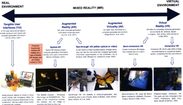
The phrase "augmented reality" describes one subcategory of the Mixed-Reality(MR) interfaces represented in Figure 2-1. Milgram and Kishino describe MR as a percep-tual merging of real and virpercep-tual worlds. Augmented Reality(AR) develops when a live camera feed or an object in the physical environment is augmented with com-puter graphics. Augmented Virtuality(AV) results when virtual environments are supplemented with live video from some part of the "real world." [68]
Some of the most prevalent of MR systems combine physical and digital work-stations. In an expansion of his 1991 work "The DigitalDesk calculator: tangible manipulation on a desk top display," Pierre Wellner created a full "digital desk" that supported camera digitization of numbers on physical paper for use on the calculator, which was projected onto the desk [98]. It is now possible to project images onto
ob-VIRTUAL ENVIRONMENT
continuum[68] ... . ...
jects and canvases of arbitrary shape [10], enhancing the similarity between AR and
TUI and increasing the likelihood that AR interfaces will eventually have a haptic
component. Another method to mix realities uses a mobile phone or PDA instead of a projector to create a "magic window" into the digital version of a scene [60].
On the other side of the MR continuum, Malik and Laszlo bring the user's hands onto the computer desktop for a compelling implementation of direct manipulation
[62]. In an extension of this project, Malik et al. enable more flexibility in camera
position by placing a fiduciary marker next to the touchpad surface [63]. These types of markers, common to MR and tangible systems, are the subject of the next section.
2.3
Fiducials
Tagging physical objects gives them a digital identity. It is well known that laser-scanned barcodes are used for inventory management and price lookup in stores and warehouses. We also know, from the discussion above, that two-dimensional markers, called fiduciary markers, are common in MR systems. Indeed, the ARTag architecture provides markers intended for identification and pose estimation in augmented reality systems [101]. Markers can also be found enabling tangible interfaces-the reacTIVi-sion table uses "amoeba" tags to detect the position and orientation of the tokens [50] and the TrackMate project aims to simplify the process of building tangible interfaces with its circular tags [53].
As markers can be distracting, some tracking systems employ computer vision techniques such as template matching or volume modeling that can reduce or elim-inate the need for tags, but according to Lepetit and Fua, "Even after more than twenty years of research, practical vision-based 3D tracking systems still rely on fidu-cials because this remains the only approach that is sufficiently fast, robust, and accurate." [58]. For this reason, one alternative to purely vision-based approaches uses markers that, while imperceptible to the human eye, remain visible to cameras in the infrared band [76]. Another option uses time-multiplexing to project markers such that they are only visible to a camera synchronized at a certain frequency [36].
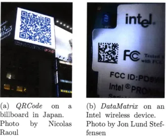
(a) QRCode on a (b) DataMatrix on an
billboard in Japan. Intel wireless device.
Photo by Nicolas Photo by Jon Lund
Stef-Raoul fensen
Figure 2-2: Examples of 2D Barcodes from http://commons.wikimedia.org
Another benefit to using markers is the ability to provide unique identity to objects or actors. Even the best computer vision algorithm would have difficulty distinguishing between two very similar objects, but an imperceptible marker would make it trivial. Markers, in one form or another, are here to stay.
With the increasing popularity of mobile devices and smart phones, ubiquitous computing has become truly ubiquitous. Along with these compact computing plat-forms, fiduciary markers have left the laboratory and are finding their way into com-mon interface technologies. Two-dimensional barcodes are gaining surface area in and on magazines, t-shirts, graffiti, consumer devices, shipping labels, and advertisements
(see Figure 2-2). When decoding the Quick Response(QR) code-a two-dimensional barcode used to encode web addresses-a delay is perfectly acceptable; much of the current research focuses on decoding from any angle and under varied environmental conditions [18, 20]. Other research seeks to improve performance by utilizing network connectivity, sending a compressed image and performing the actual decoding on a remote server [99]. This approach still falls short of real time performance-a vital problem for interface development [21]. Indeed, one project that focuses on using mobile cameras for real-time decoding of a Data Matrix code has met with some difficulty [6].
In contrast with many of these projects, our approach to using fiducials for
teraction switches the position of the camera and the barcode. The BoPen can be produced inexpensively as a stand-alone device or embedded in a PDA or cell phone, uniquely identifying users to any system with a camera. Furthermore, mobile devices are limited in display and processing power. While mobile phones may eventually be able to recognize fiducials for real-time interaction, personal computers and those driving large displays are likely to arrive there sooner. What's more, some of the limitations of using a PDA as a small window-like portal into an augmented reality can be circumvented by intelligent projection, and a combination of the two can yield a richer interaction experience [83].
2.4
Bimanual Interaction
One of the great draws of tangible interfaces, mixed reality, and multitouch systems is the ability to simultaneously use both hands for interaction. In 1997, Hinckley et al. confirmed the predictions of Guiard's kinematic chain model as applied to lat-erally asymmetric tasks; for three-dimensional physical manipulation with a tool in one hand and a target object in the other, the dominant hand was best for fine (tool) manipulation whereas the non-dominant hand was best for orienting the target [42]. This study was performed with right-handed subjects and demonstrated that the ob-servable effects of asymmetry increases with task difficulty. The results also reflect our everyday behaviors; people are used to holding a book with one hand, and mark-ing it with the other. In one extension of this research to pen user interfaces, Li et al. reported, based on a keystroke-level analysis of five mode-switching methods, that using the non-dominant hand to press a button offers the best performance by a wide margin, even when the placement of the button is non-ideal
[59].
These findings, reported in 2005, are not surprising. Watching Alan Kay present a video demon-stration (http://www.archive.org/details/AlanKeyD1987) of Sutherland's Sketchpad[86], one realizes that this bimanual model was used in the interface he implemented
over 40 years ago!
even when the asymmetry is sympathetic to handedness
[56].
Keeping track of two mouse cursors and the functions they represent can be difficult. Indeed, given the option of performing symmetric tasks with touch or with a mouse, participants pre-ferred touch, even though the accuracy of touch decreased rapidly with distance and resulted in more selection errors [29]. It is possible that applying an adaptive point-ing technique to a pen-controlled cursor could provide an all-around better means of interaction. However, if touch is available as well, it might be best to use both. Brandl et al. showed that a combination of pen and touch is best for speed, accuracy, and user preference, in comparison to both the pen/pen and touch/touch alternatives[13]. This finding lends credibility to the notion that the pen-touch combination feels
more natural while providing a more efficient and accurate interface for certain tasks.
2.5
Conclusion
We have seen that modern developments in input technologies enable extending tra-ditional input devices to take advantage of up to six degrees of freedom. Noting that tangible and mixed-reality interfaces area commonly use objects for 6-DOF interac-tion, we looked at how these interfaces are enhanced by the markers and dynamic binding, as in the associate-manipulate paradigm or with binding virtual objects to physical fiducials. Finally, we described the potential benefit to using multiple modes of interaction, especially when interacting bi-manually.
The BoPen is an inexpensive input device that could bind to virtual objects for direct 6-DOF manipulation. It could also function as a pointer for precise, localized input. In both cases, it might be easiest to use a system that employs multiple pens or modalities. Utilizing asymmetric bi-manual action could facilitate rapid mode and association switching, enabling an interaction that is both flexible and natural.
Chapter 3
Design Development
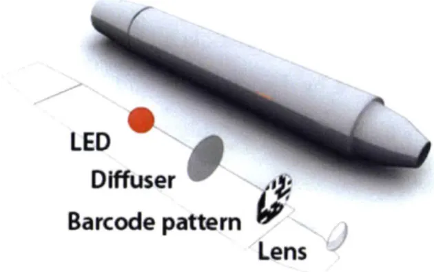
LED Difuser Barcode pattern LensFigure 3-1: BoPen: Basic Design
3.1
BoPen Overview
The BoPen contains an LED, a diffuser, a transparency, and a lens, as seen in Figure
3-1. The optics are aligned such that a tiny pattern on the transparency will be
projected into infinity. To the human eye-or a camera focused at the front of the pen-the pattern is not visible. Instead all that can be seen (if the LED is in the visible range of the spectrum, in the case of the human eye) is a small point light source. However, when a camera focuses at the infinite plane, the pattern on the
Camera
Sensor:
(a) A pinhole placed in front of a
bar-code pattern enbar-codes directional rays with the pattern. The camera captures this in-formation by positioning the sensor
out-of-focus. An unbounded magnification
is achieved by increasing sensor-lens dis-tance, limited only by the signal-to-noise ratio.
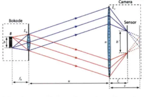
(b) A small lenslet placed a
fo-cal length away from the pattern creates multiple directional beams (ray bundles) for each position in the barcode pattern. The camera lens, focused at infinity, images a magnified version of the barcode pattern on the sensor.
Figure 3-2: Optical Models: Pinhole (left) and Lenslet (right).
mask appears in a circle of confusion, or bokeh (pronounced "bouquet") around the light. The circle itself is created by defocus blur, and its size and shape are dependent on the properties of the camera, most notably its aperture.
3.1.1
Bokode Optics
We will now briefly introduce the enabling optical technology for this system. For a more complete description, please refer to [70].
With the BoPen's optical configuration, the information of the barcode patterns is embedded in the angular and not in the spatial dimension. By placing the camera out-of-focus, the angular information in the defocus blur can be captured by the sensor. The pinhole is blurred, but the information encoded in the bokeh is sharply imaged.
Looking at the pinhole setup in Figure 3-2(a), one can imagine that the barcode image-as seen by a stationary observer-will be made arbitrarily large by simply mov-ing the lens more out-of-focus. When the lens is one focal length away from the source image, the rays traced from a single point come through the lens collimated (parallel). In this case, the lens is focused at infinity and the magnification remains
14% I"0%5 L'"&M I"'f
Figure 3-3: Data Matrix-Based Pattern Design. A tiled arrangement of Data Matrix
(DM) codes encodes identification and angular information. Each 10 x 10 symbol stores both its physical position in the overall pattern and a unique byte identification code that is repeated across all DMs in the Bokode. Image from [70].
constant despite changing the observer distance: the size of the observed image is
depth-independent. As relatively little light can enter through a pinhole and the little
that does is extensively diffracted, the Bokode and BoPen utilize a lenslet in the same position, as seen in Figure 3-2(b).
The camera images a different part of the pattern depending on its position rel-ative to the pen. The viewable region of the transparency is a function of the angle formed between the camera position and the BoPen's optical axis. Unlike traditional barcodes, Bokodes have the ability to give different information to cameras in different positions/orientations [70]. In the BoPen, this feature is used to provide information about the angular tilt of the pen with respect to the drawing surface.
3.1.2
Preliminary Pattern
We based our initial pattern on the Data Matrix code, and it is identical to the one described in [70]. The Data Matrix (DM) is a two dimensional barcode [45] that uses a matrix of binary cells to store information. As shown in Figure 3-3 the Bokode uses a tiled array of 10 x 10 DM codes with one row/column of silent cells between adjacent codes. One 10 x 10 DM encodes 3 bytes of data and another 5 bytes of Reed-Solomon error correcting code. This error correcting code ensures data integrity even when up to 30% of the symbol is damaged; we can also rely on this redundancy to help
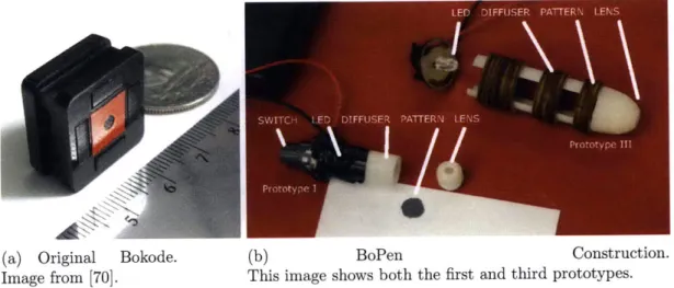
(a) Original Bokode. Image from [70].
(b) BoPen Construction.
This image shows both the first and third prototypes.
Figure 3-4: Comparison of the original Bokode design and the BoPen.
disambiguate between overlapping patterns. Since which pattern is visible depends on the camera angle, the tiled DM design offers up to three independent bytes of information that can vary with tilt to provide both identification and orientation information based on how the pen is positioned relative to the camera. Two bytes provide the the x and y positions of the currently visible Data Matrix. The remaining byte is common across all DM codes in a single pen, providing consistent identification information that is independent of pen orientation.
We ordered a printed film mask with these patterns sized at 20x20pm per pixel from PageWorks company in Cambridge, Massachusetts, USA. Each DM in a 128x128 matrix encodes the same unique identifier, and the layout encodes row and column information as detailed above. The transparencies were cut by hand and positioned in the pen as described below.
3.2
Building the BoPen
We tested several hardware designs before selecting and iterating upon a final version. Figure 3-4(a) shows Mohan et al.'s original Bokode, while Figure 3-4(b) shows two of our pen-based prototypes. Prototype I was approximately 10 mm wide and 5 cm long with a high-intensity red LED connected to a pushbutton and an external battery case. It was designed with the software program Rhinoceros@ and printed in two
(a) SolidWorks drawing for 3D (b) Lasercutter patterns for adjustable
printing. and modular slices.
Figure 3-5: Components of final pen design.
pieces on a Dimension 3D printer. A tap and die enabled us to put threads on the two pieces and fit them together, once we had glued the patterned transparency to the back of the tip piece. For this to work, the tip's length had to be exactly the focal length of the lens.
After our proof-of-concept experiment (described below in Section 3.3.1), we built our second prototype. Prototype II (not shown) was similar to the first but scaled up, utilizing a larger lens to increase the amount of light it emitted. Unfortunately, the walls were too thin to tap without breaking. This problem-combined with the difficulty of achieving proper focus with the fixed position of the mask-convinced us to completely re-design the pen to enable a more flexible option for focusing.
Prototype III was designed in SolidWorks@ and also printed on the Dimension printer (Figure 3-5(a)). Rather than an assembly of two pieces, this version utilizes laser-cut slices that can be moved around during testing and fixed in place with additional laser-cut spacers. The slices were cut in a variety of shapes to provide holders for all the component pieces of a BoPen (Figure 3-5(b)). They were cut from wood and paper of varying thicknesses to facilitate focusing. Prototype III was the final redesign, but further iterations based on lens choice are described in Section 4.2.2. Most pens created from this design are approximately 20 mm wide and 6 cm long. This larger pen provided room for a wider pattern, enabling an associated increase in the theoretical angular range for lenses with a relatively small focal length.
b(a)
[~~] (e)
(d)
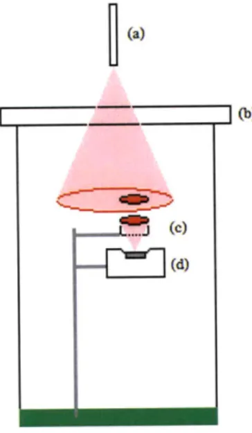
Figure 3-6: Diagram of arrangement for first test. (a) BoPen (b) Clear Tabletop (c)
50mm Lens (d) Camera, with bare sensor exposed.
The increased size also resulted in a pen that is more natural to hold. Prototype I was reminiscent of a tiny disposable pencil, whereas Prototype III felt more like a short marker.
3.3
Software and System Iteration
With our first prototype, we sought to replicate the off-line results obtained in the original Bokode experiments, but with a web-cam instead of an expensive digital SLR. We also wished to create a computational pipeline for identifying the location of a bokeh in an image and extracting and processing the DM codes. Then, we could work to optimize this process and work toward a real-time system. We planned to do this through an iterative process of evaluations and improvements. This section describes a few cycles of this process.
3.3.1
Replicating Bokode
For our proof-of-concept, we used a Philips SPC-900NC web-cam with the optics removed to expose the CCD. A Canon@ 50mm camera lens set at infinite focus
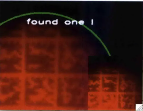
Figure 3-7: First Software Version. Running in "Images Visible" mode. There is
a small red dot to indicate the center of the found circle, and the thumbnail in the bottom right shows the histogram-normalized image sent to the Data Matrix decoder.
was aligned with the CCD, and a piece of transparent acrylic at 0.5m served as our drawing surface. Figure 3-6 shows a rough sketch of the physical layout. We used our first BoPen prototype as described above, and recorded data at 5 frames per second and 320x240 resolution. This data was interpreted by software written in C++ that made use of open source libraries, specifically IBM's Open Computer Vision (OpenCV) library and the Datamatrix Libraries (LibDMTX).
First Version Software
Our initial software was designed to interpret data from a video recording. For each frame, it first performs filter operations followed by a polar Hough transform to find circles present in the image (Figure 3-7). A predefined number of pixels (the "win-dow") around the circle center is cropped, normalized, and passed to the DM decoding library for interpretation. The software reports the number of frames processed, the number of barcodes found, and the total time taken for processing.
Performance Evaluation
For our first test, we processed 268 frames from a 53-second video clip captured in the manner described above at five frames per second. Using no scaling and a window size of 120 pixels, we found and interpreted codes in 22% of frames over the course of 374 seconds. This was unacceptable, so we tried scaling the images (and window
... .... . . .... ... ... .. .... ...
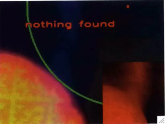
Figure 3-8: Example: Image Processing Failure. In this example, the background
noise in the red channel resulted in incorrect circle identification and, subsequently, an inordinate delay in DM decoding.
size) down by a factor of two. This action resulted in the same recognition rate, but the processing took only 112 seconds (about half of real-time speed). By increasing the size of the window region, we were able to improve the recognition rate to 47.4% in only 89.7 seconds.
Unexpectedly, using larger window sizes with the scaled-down lower resolution images resulted in both a higher recognition rate and a shorter processing time. This result was observed even when sending the entire scaled-down image to the DM decoding library, instead of using circle detection to determine which frames warranted interpretation. In some cases the circle detector incorrectly identified the salient region, as seen in Figure 3-8. In subsequent versions, we removed the circle detector entirely.
3.3.2
Diffuser Experiment
In our first design, we were only able to move the device around a small portion of the table before it was no longer visible by the camera. Our first attempt to improve the system ambitiously sought to enable interaction across the entire table-increasing the field of view by imaging onto a diffuser. This enabled us to move the BoPen within a rectangular region of approximately 33 x 22 cm at a distance of 0.5m-more than enough space for multiple users to interact. Unfortunately, the diffusers degraded the
(b)
En(e)
Figure 3-9: Diffuser-Based FOV Enhance- Figure 3-10: Mock-up of Diffuser Imaging ment. Imaging onto a diffuser-even one Setup. (a) BoPen (b) Clear Tabletop (c)
designed for image projection-causes sig- 50mm Lens (d) Diffuser (e) Camera, with nificant artifacts from the grain of the ma- lens focused onto diffuser.
terial.
image quality to the point where we could no longer decode the Data Matrix (Figure
3-9). We made a number of attempts to use smoothing and other image processing
methods to clean up the image, but were unsuccessful in decoding the DM with this configuration. Though the implementation fell short of our goals, it provided us a more in-depth understanding of the optical limitations. In the future, we might try to design a pattern that projects more clearly onto a diffuser or, alternately, use an optical taper to scale down without degrading image quality.
3.3.3
Live Tracker
After our unsuccessful diffuser experiment, we decided to focus on getting the sys-tem to operate more quickly. Though it is less likely we could develop a successful multi-user system with only a portion of the table as input, the popularity of the mouse and the pen tablet attest to the great number of interesting single-user appli-cations we could explored. The refined system now described is based on a similar optical configuration to the first version. However, instead of reading images from a prerecorded file, it processes live video frame-by-frame.
Figure 3-11: Software Pipeline: Version Two. A distinguishing feature of this
real-time tracker is that it runs the Data Matrix decoder in a separate thread. This choice means that although the blob centroid detection is reported in real time, the decoded
ID numbers and angle positions are at least a few frames behind.
Second Software Version
Since DM decoding is essential to 3 of the 6 degrees of freedom we planned to support, we went back to imaging through a 50mm camera lens onto a bare sensor. This time, we chose a camera that had the capability of a higher frame rate-an older PointGray@ DragonflyT M with better resolution than the Phillips web-cam, but still well within the range of "commodity cameras." The choice to use a bare sensor resulted in a 4-to-5-fold reduction in our field of view and a corresponding increase in the resolution. As we expected, this enabled us to again decode Data Matrices. We also significantly
altered our pipeline, as shown in Figure 3-11 and described below:
A frame captured from the camera is Bayer-encoded grayscale, so it must first be
converted to an RGB image. Next the image is scaled down by a factor of four and split into component colors. Due to the observed irrelevance of the circle detection
(a) System detecting a single centroid (b) System detecting two centroids and de-(green "X") and interpreted barcode data coding one of the two patterns. This kind (White "One") from a recent frame. When of split was often observed.
this image was captures, the label indicat-ing successful DM decodindicat-ing was unwaver-ing. Note the small, monochrome, edge-detected blob image in the bottom left.
Figure 3-12: Multiple Simultaneous Detection and Disambiguation.
during our initial experiments, we decided to omit it from this version of the pipeline. Instead, the red and blue images are thresholded to create a binary image in which we find blobs corresponding to bokehs, calculating their centroids.
The regions in the green channel corresponding to discovered blobs in the thresh-olded image are copied, normalized, smoothed, and sent to a separate thread which runs the DM decoder. Up to a variable ten of these threads can be active at a time, and frames are dropped (ignored) until there is space in the queue. Because the sys-tem is threaded, the blob detection portion of the program continues to run, tracking centroid location. When a DM has been decoded in this separate thread, the decod-ing thread is joined with the main thread (usually 2-5 frames later) and the identifier is displayed.
Performance Evaluation
The first live system performed very satisfactorily. It could consistently detect: * How many pens were in the field of view
* The approximate coordinates of each pen
" Each pen's unique identifier
Examples of system output can be seen in Figures 3-12(a) and 3-12(b). The system was never observed to confuse one device for the other, and it was observed on multiple occasions to decode two barcodes simultaneously-from images taken from the same or directly adjacent frames. However, the performance was inconsistent between two devices: In a sample of approximately 200 frames where the pens were at rest, the code in the device labeled "One" was available in 58% of frames. For the device labeled "Two," that number was substantially less: 13%. This is most likely the result of device-specific focus or dust/smudging occlusions issues.
3.3.4
Lessons Learned
There were three main weaknesses in this version of the BoPen, which prevented us from making it into an interface device:
e No detection of roll orientation, and no use of the decoded tilt data. Both
these weaknesses are a matter of software implementation; roll angle can be calculated based on the orientation of the DM, and the tilt can be calculated from the decoded row and column information in the Bokode.
* No model for changing position over time. Perhaps the greatest limitation is
that this system has no model for changing position over time. We separately detect bokeh position and identification, but there is nothing to associate the two. For this reason, we chose only to use the identification functionality of the Bokode, and not its tilt-detection capability.
o Lag between position detection and DM decoding. Even if we did model a device over time, the tilt and roll information would lag a second or two behind the position data. This prohibits the system from producing tilt and roll data at a rate adequate for the quick response times required by a direct-manipulation interface.
Another limitation comes in the form of the light-based noise to which all optical systems are susceptible: additional emitters in the scene would reduce image contrast.
A related difficulty arises when attempting using this system with a projection
surface-based display; the diffuser obscures the signal, so we cannot use this pen on a back-projected display. One alternative suggested by Han is illumination using infrared light, as it is less occluded by LCDs [39]. A more promising alternative-a collaboration with Microsoft Research-is explored in the next section. The SecondLight system uses a variable diffusivity surface that is constantly oscillating, enabling the SecondLight team to display both on and above the surface [46], and enabling the image from the BoPen to be captured from beneath.