Publisher’s version / Version de l'éditeur:
Proceedings of the Medicine Meets Virtual Reality(MMVR 2006), 2006-01-24
READ THESE TERMS AND CONDITIONS CAREFULLY BEFORE USING THIS WEBSITE. https://nrc-publications.canada.ca/eng/copyright
Vous avez des questions? Nous pouvons vous aider. Pour communiquer directement avec un auteur, consultez la
première page de la revue dans laquelle son article a été publié afin de trouver ses coordonnées. Si vous n’arrivez pas à les repérer, communiquez avec nous à PublicationsArchive-ArchivesPublications@nrc-cnrc.gc.ca.
Questions? Contact the NRC Publications Archive team at
PublicationsArchive-ArchivesPublications@nrc-cnrc.gc.ca. If you wish to email the authors directly, please see the first page of the publication for their contact information.
NRC Publications Archive
Archives des publications du CNRC
This publication could be one of several versions: author’s original, accepted manuscript or the publisher’s version. / La version de cette publication peut être l’une des suivantes : la version prépublication de l’auteur, la version acceptée du manuscrit ou la version de l’éditeur.
Access and use of this website and the material on it are subject to the Terms and Conditions set forth at
Computer Prediction of Balloon Angioplasty from Artery Imaging
Laroche, Denis; Delorme, Sebastien; Anderson, Todd; Buithieu, Jean;
Diraddo, Robert
https://publications-cnrc.canada.ca/fra/droits
L’accès à ce site Web et l’utilisation de son contenu sont assujettis aux conditions présentées dans le site LISEZ CES CONDITIONS ATTENTIVEMENT AVANT D’UTILISER CE SITE WEB.
NRC Publications Record / Notice d'Archives des publications de CNRC:
https://nrc-publications.canada.ca/eng/view/object/?id=81dedc8c-d0d9-4983-84bd-cc18d383a3b7 https://publications-cnrc.canada.ca/fra/voir/objet/?id=81dedc8c-d0d9-4983-84bd-cc18d383a3b7Computer Prediction of Balloon
Angioplasty from Artery Imaging
Denis LAROCHE a,1, Sebastien DELORME a, Todd ANDERSON b, Jean BUITHIEU c, and Robert DIRADDO d
a
Industrial Materials Institute, Boucherville, QC, Canada
b
University of Calgary, AB, Canada
c McGill University Health Center, Montreal, QC, Canada
Abstract. The success of angioplasty depends on a balance between two conflicting objectives: maximization of artery lumen patency and minimization of mechanical damage. A finite element model for the patient-specific prediction of angioplasty is proposed as a potential tool to assist clinicians. This paper describes the general methodology and the algorithm that computes device/artery friction work during balloon insertion and deployment. The potential of the model is demonstrated with examples that include artery model reconstruction and prediction of friction on the arterial wall during balloon insertion and deployment.
Keywords. Finite elements, model, angioplasty, multi-body contact, friction.
Introduction
Cardiovascular diseases are the first cause of death in the western world. Balloon angioplasty, the most practiced medical intervention worldwide, consists of dilating a stenosed artery with a polymeric balloon in order to restore blood flow to an acceptable level. Often, a metallic slotted tube called stent is deployed and permanently implanted inside the artery to prevent elastic recoil of the artery. The most frequent complication of angioplasty, restenosis, is an excessive repair reaction of the arterial wall, related to its mechanical damage during the intervention. Restenosis has been shown to be related to two types of mechanical damage: 1) overstretch injury of the arterial wall and 2) denudation of the endothelium (the cell monolayer that lines the interior part of the arterial wall) due to friction with the balloon. The specific contribution of both types of injury to restenosis is still debated [1,2]. Whether because of patients comeback after 6 months for target vessel revascularization or because of the use of expensive drug-eluting stents, it is generally recognized that restenosis increases by 25 to 30% the total cost of this intervention, which in Canada results in a 50M$ increase on the annual healthcare burden.
The success of angioplasty depends on a balance between two conflicting objectives: 1) maximizing the final deformation of the artery and 2) minimizing the mechanical damage to the arterial wall. Few research groups have attempted to simulate angioplasty with numerical or analytical models and predict its outcome.
1 Corresponding Author : Denis Laroche, Industrial Materials Institute, 75 de
Angioplasty simulation, combined with current artery imaging technique such as intravascular ultrasound (IVUS), has the potential to become a clinical tool to assist in the selection of an appropriate intervention strategy for a specific patient. This could be done by virtually testing various strategies. However to render the tool clinically useful, two often competing requirements must be met: high accuracy of the predicted behavior and high computational speed.
This work presents improvements to a finite element model for predicting the device/artery behavior during angioplasty [3-5]. They consist of the integration of artery model reconstruction and the development of a new multi-body contact algorithm to reduce computational time and increase its robustness. Calculation of friction work is also proposed as an hypothesized predictor of endothelium denudation. To our knowledge, friction damage to the endothelium has never been considered in angioplasty simulations, possibly because of the difficulty of implementing a robust contact/slip algorithm for deforming bodies. An example of balloon angioplasty simulation on a coronary artery obtained from intravascular ultrasound imaging is presented to demonstrate the potential of the proposed model.
1. Methodology
A finite element modeling software developed for the analysis of large deformations of soft materials is used to solve angioplasty mechanics [3-5]. The model computes the device/artery interaction and large deformations that occur during device insertion and deployment into the diseased artery. It predicts the resulting artery lumen patency, including stress and strain distribution in the arterial wall, for a specific device and inflation pressure. The software uses conjugate gradient methods with various pre-conditioners to iteratively solve the system of equations.
1.1. Angioplasty Procedure Model
As described in a previous report [3], the angioplasty device model consists of a balloon being wrapped onto a rigid catheter. The balloon is modeled with membrane elements and the Ogden hyperelastic constitutive equation. The artery is modeled with incompressible solid elements and the Mooney-Rivlin hyperelastic constitutive model. Tetrahedral elements rather than hexahedral elements are proposed for the artery, thus allowing the use of automatic mesh generation from medical images, and reducing the time required for processing the data. The simulation steps include the balloon pre-folding onto the rigid catheter, the insertion into the artery, and its complete deployment to dilate the target lesion. During balloon insertion, the friction exerted on the arterial wall significantly deforms it and depends upon the boundary conditions on the artery.
1.2. Implicit Multi-body Contact Algorithm
Contact algorithms are usually time consuming and limiting factors in complex finite element applications. They have been traditionally used in explicit software and include collision detection [6,7], non-penetration constraint and friction/slip capabilities [8,9]. Collision detection algorithms can be explicit (position based) or implicit (trajectory based). However, very few papers discuss the robustness of each
approach and their application to implicit finite element computation, particularly the problems associated with the "dead-zone" or with the thin membrane collision detection.
An important contribution of this work is the development of a multi-body contact algorithm that is rapid and robust enough to handle complex contact and friction behaviors between the balloon and the artery. Collisions between virtual nodes and surfaces moving with large displacement steps are detected with an implicit iterative approach that fully respects the non-penetration constraint. At every displacement increment, the positions of the virtual nodes are computed as a minimization problem with the objective function F being their distance to the finite element mesh, subject to a non-penetration constraint g. The problem is given by Eqs. (1) and (2), with XVi and
XFEi being the positions of the virtual nodes and those of the finite element mesh, respectively. ( )
∑
= − = N 1 i FEi Vi Vi X X X F (1)(
X ,X)
N(
X X)
0 g Vj Vk = Vk⋅ Vk− Vj ≤ (2)Indices i represent all the surface nodes while j and k are for contacted nodes and surfaces, respectively. NVk and XVj are the virtual surface normal vector and the position of one of its connected nodes, respectively. This technique is stable for large displacement increments and is therefore directly applicable to implicit finite elements. Once contact is detected, it is handled with an augmented Lagrange algorithm that computes slip and friction forces.
2. Simulation Examples
The example includes two simulations of balloon angioplasty on the mid-LAD coronary artery of a patient. The various steps involved in the construction of the models for the artery and the angioplasty device, as well as the intervention simulation are presented. The contact algorithm used approximately 18% of the total computational time for each simulation.
2.1. Artery Model Reconstruction
The artery model was reconstructed from intravascular ultrasound (IVUS) images of a percutaneous coronary intervention (PCI). The intervention included several balloon deployments and the implantation of three stents. Three IVUS pullbacks were performed during the procedure at a pull-back speed of 0.5 mm/sec. The first IVUS sequence was used in this example to build the finite element mesh of a 66-mm long artery segment. Equally spaced images (one per cardiac cycle) were selected and imported into the Amira software (Mercury Computer Systems, Chelmsford, MA) as a 120x120x136 voxel field. The average cardiac cycle rate over the whole sequence was measured from observation of the images. The lumen and media-adventitia borders were identified through manual segmentation. Interpolation between image frames was used to compensate for shadow artifacts. An initial surface mesh was created using the
marching cube algorithm. From this surface mesh, a tetrahedral mesh was then produced using the advancing front method. The 11553-node mesh was edited to avoid tetrahedrons with a large aspect ratio, in order to prevent ill-conditioning of the finite element problem.
2.2. Angioplasty Using a Short Balloon
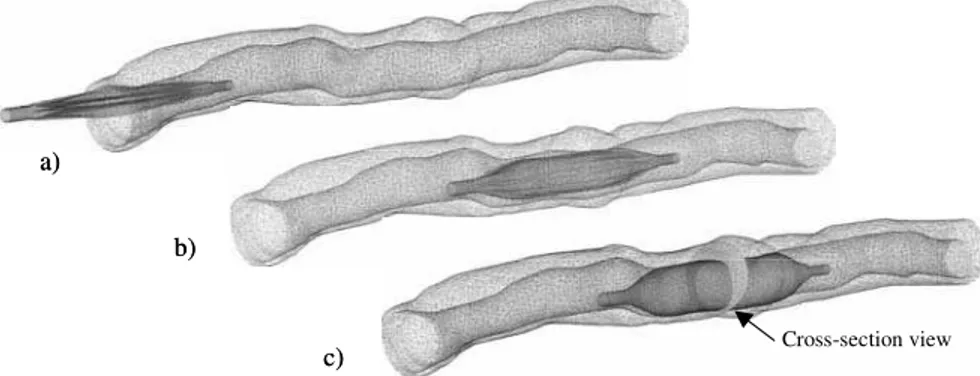
In this example a 12-mm long angioplasty balloon having a deflated diameter of 3.2 mm (nominal diameter of 3.5 mm at 8 atm) was used. Previously mounted onto a rigid catheter and folded with the use of four folding blades, the balloon was gradually inserted into the artery up to the most stenosed segment. Then an internal pressure of 12 atm was gradually applied to fully deploy the balloon and dilate the artery lumen.
Figure 2 shows predicted deformations during the procedure. Figure 3 shows the balloon deployment mechanics and the balloon-artery interactions in a cross-section view. The distribution of stretch on the artery is represented in grey tones. As expected, the maximum stretch is located on the thinnest part of the arterial wall.
Figure 1: Example of segmented IVUS image showing lumen and media-adventitia borders.
Cross-section view a) b) c) Cross-section view a) b) c)
2.3. Angioplasty Using a Long Balloon
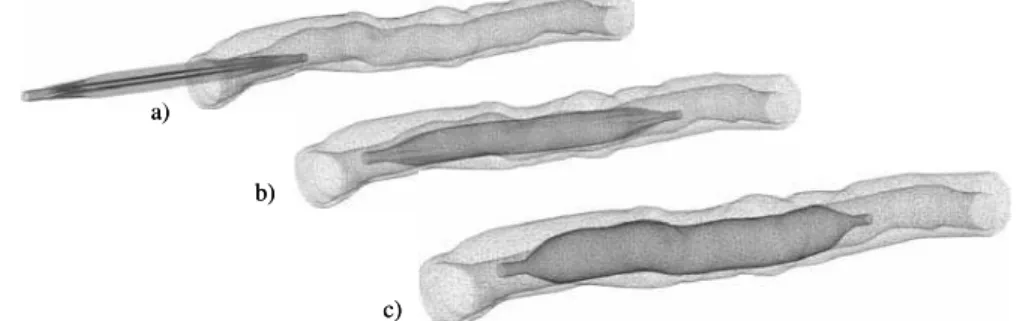
In this second example a 28-mm long balloon was used on the same artery segment. Similar simulation steps as for the short balloon were used to inflate at 12 atm. Figure 4 shows predicted deformations during the procedure. When compared to the short balloon example, the long balloon seems to deform and conform to the artery shape.
2.4. Prediction of Friction Work
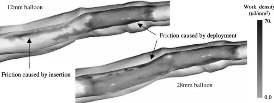
In each simulation the cumulative friction work per unit area was computed. This is expected to give an indication of the amount of damage to the endothelial cells. Figure 5 shows predicted friction work density after balloon deployment for the two examples. It can be seen that for both short and long balloons, an average friction work density of 10 µJ/mm2 was predicted on the artery where the deployment took place. Smaller yet unexpectedly high friction work due to the balloon insertion was also observed for both examples. These values can be explained by the use of a rigid catheter and by the high structural stiffness of balloon flaps. Friction work predicted on both insertion and deployment areas is high enough to potentially damage the endothelium.
λ1 (m/m) 1.0 1.2 a) b) c) d) λ1 (m/m) 1.0 1.2 a) b) c) d)
Figure 3: Cross-section view (Fig 1) of balloon deployment for the 12mm balloon. a) end of balloon insertion; b) and c) steps of deployment; d) end of deployment (12 atm).
a) b) c) a) b) c)
Figure 4: Simulation results for the 28mm long balloon. a) insertion; b) deployment; c) end of deployment (12 atm).
3. Conclusion
In this paper a finite element model for predicting balloon angioplasty from artery imaging was presented, with emphasis on new developments such as reconstruction of artery model from medical images and calculation of friction work from a new multi-body contact algorithm. A numerical example on a human coronary artery demonstrated the potential of the model to predict the mechanical interaction between the balloon and the arterial wall. In an effort to render the simulation clinically useful, the friction work exerted by the balloon was computed and presented as a potential indicator of endothelium damage. Future work will focus on constitutive models for the artery and the use of deformable catheters to further improve the accuracy of the simulation. Experimental work is underway to verify the relationship between friction work and endothelial denudation.
References
[1] Clowes AW, Clowes MM, Fingerle J, Reidy MA. Kinetics of cellular proliferation after arterial injury. V. Role of acute distension in the induction of smooth muscle proliferation. Lab Invest 1989; 60:360-364.
[2] Fingerle J, Au YP, Clowes AW, Reidy MA. Intimal lesion formation in rat carotid arteries after endothelial denudation in absence of medial injury. Arteriosclerosis 1990 10:1082-1087.
[3] Delorme S, Laroche D, DiRaddo R, Buithieu J. Modeling polymer balloons for angioplasty: from fabrication to deployment. Proc Annual Technical Conference (ANTEC), SPE, Chicago, IL, 2004. [4] Laroche D, Delorme S, DiRaddo R. Computer simulation of balloon angioplasty: effect of balloon
deployment on contact mechanics. ASM Materials & Processes for Medical Devices Conference, Anaheim, CA, 2003.
[5] Laroche D, Delorme S, Buithieu J, DiRaddo R. A three-dimentional finite element model of balloon angioplasty and stent implantation. Proc Comp Meth Biomech Biomed Eng 5, Madrid, 2004.
[6] Hallquist JO, Goudreau GL, Benson DJ. Sliding interfaces with contact-impact in large-scale lagrangian computations. Comp Meth App Mech Eng 1985; 51:107-137.
[7] Zhong ZH. Finite element procedures for contact-impact problems. Oxford University Press, 1993. [8] Laursen TA, Simo JC. A continuum-based finite element formulation for the implicit solution of
multibody, large deformation frictional contact problems. Int J Num Meth Eng 1993; 36:3451-3485. [9] Puso MA, Laursen TA. A mortar segment-to-segment contact method for large deformation solid
mechanics. Comp Meth Appl Mech Eng 2004; 193:601-629.
Work_density (µJ/mm2) 0.0 70. 12mm balloon 28mm balloon Friction caused by insertion
Friction caused by deployment
Work_density (µJ/mm2) 0.0 70. 12mm balloon 28mm balloon Friction caused by insertion
Friction caused by deployment