Prof. J. R. Zacharias V. J. Bates J. H. Holloway Prof. J. G. King D. S. Edmonds, Jr. C. L. Searle Dr. C. L. Schwartz R. D. Haun, Jr. G. W. Stroke
B. B. Aubrey R. Weiss
A. MEASUREMENT OF THE VELOCITY OF LIGHT
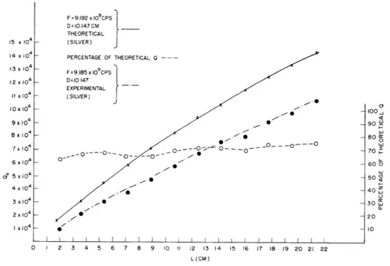
Experimental Q measurements were performed with the "moderate precision" cavity, described in the Quarterly Progress Report of April 15, 1956, page 31. We recall that the inner diameter of the cavity is 10. 15 cm; the maximum available length, 22 cm.
The experimental conditions were arranged in a manner that would minimize the external
Q;
the results quoted can therefore be taken as furnishing values for the unloaded Q of the cavity as well. The equipment used for measuring the Q of the cavity consists of two phase-locked oscillators (see Quarterly Progress Report, April 15, 1956, p. 37), the first of which is an S-band klystron locked to a 5-mec crystal oscillator. The second phase-locking circuit locks a V-270 X-band klystron to the third harmonic of the S-band oscillator. The V-270 klystron can be tuned very precisely through the resonance of the cavity by varying the frequency of the 200-kc second reference oscillator in the S-band loop. Maximum deviations at X-band of the order of 400 kc can be achieved reliably with this apparatus.These measurements were undertaken, partly, in order to ascertain the accuracy of the theoretical predictions of the values of the Q's. We found that the Q's ranged from
104 for the second node to values greater than 105 at the twelfth node for the TE01N
mode at a frequency of 9195 mc. The spread of measurement values was not more than ± 3 per cent. The guide half-wavelength is 1. 774 cm. The values of the Q's ran from
62 per cent to just under 80 per cent of their theoretical values. Details of these meas-urements are shown in Fig. VII-1.
Some other empirical questions that were answered in the course of these experi-ments can be summarized as follows:
a. Satisfactory power transmission was obtained through the 3-mm iris feeding and receiving holes, the attenuation being 25 db per hole.
b. The
Q
was affected noticeably by eccentricities of the order of 0. 004 inch for a total radial clearance of 0. 03 inch.c. Tilts in one meridian section of the order of plus or minus 3 X 10⁻⁴ radian of one of the pistons changed the percentage of theoretical Q at the twelfth node from 76.7 per cent to almost 74 per cent and 72 per cent, respectively.
The quality factor can be written (1) as
t n (Xg/k)2
Q
=
(1)
o (n a Xg) + (4/S /6 )
which gives, for the diameter D
=
10. 147 cm and for the frequency f
=
9192 X 109 cps,
o= 50900 (0. 099 n) + (3. 0896)
The first term in the denominator corresponds to the wall conductivity losses; the second term to the plate conductivity losses; therefore we would expect the end-plate losses to predominate in the measurement range used. The maximum value of the first term at the twelfth node (n = 12) is 1. 188, which is still small compared with 3. 0896. Both dielectric and iris losses were neglected. The constant percentage of theoretical
Q over the cavity lengths (2 cm - 21. 3 cm) indicates that most of the excess loss is caused by the end plates.
F =9.192 x 10⁹CPS D =10.147CM THEORETICAL (SILVER) PERCENTAGE OF THEORETICAL Q ---F=9.185 x I09CPS D=10 147 EXPERIMENTAL (SILVER) 0 -- '_ o -o---O -- 0 ... 0--- -__ _ 0 - - O/ 7 . I I I I I I I I I I I I i i i i 0 1 2 3 4 5 6 7 8 9 10 11 12 13 14 15 16 17 18 19 20 21 22 L(CM)
Fig. VII-1.
Experimental
Qo
curves for silver-plated, cylindrical, pyrex cavity.
We concluded that these empirical results were most encouraging and pointed to the
feasibility of an actual measurement of the velocity of light in the near future. For this
purpose, an "intermediate precision" cavity with 0. 0001-inch tolerances will be ordered
and should be available soon. The "high precision" fused-quartz cavity, with a tolerance
of the order of millionths of an inch, will not be available for at least six months. We
should like to point out that the experiments just described were carried out with the
"moderate precision" cavity, with tolerance of the order of 0. 0015 inch. In future
experi-ments with this cavity we plan to use selected plate glass with optically good surfaces
15 x 104 14 x 104 13 x 104 12 x 10O4 11 x10 4 IOx IO4 9x IO4 6 x 1O 4 o 5 x10 4 x 10 2 x I0 4 1x 10 4 o 100. 90 _ 0 70 c 60 0 50 40 30 u 20 10
I
SF = 24 x 109 CPS D = 10.147 GM * F = I0o CPS D = 14 CM O F = 9 x 10⁹CCPS D = 14CM x F = 9.192 x10 CPS D = 10.147 CM SF = 8 x 10⁹ CPS D= 14CM * F = IOtCPS D = 18.7 CM CM 27x I04 25 x I04 23x 104 - 4-21 x 10 4-19 x 104 4 17 x 10 4-15 x 10 4 13x 10 II x 10 4-9 x 10 7 x IO~ g- 7.313CM I I I I I I 0 2 4 6 8 10 12 14 16 18 20 22 24 L (CM)VII-2. Theoretical Qo curves at resonant positions in the TEo1N mode for silver-plated, cylindrical, pyrex cavity.
for end plates instead of the present silvered brass surfaces. By evaporating the silver in vacuum, rather than depositing it electrolytically, we expect to increase the Q's by a
still greater amount.
Several theoretical calculations were carried out with the aim of reaching a properly balanced choice of cavity diameter, forcing frequency, and Q. The general form of the experiment can be expressed as
f x (correction factor)
f x (correction factor)
c=fXk(3. 832/rD)2 + (n/2L)2 (3. 83z/rD)2 + (1/kg) 1/2
It is important to suppress the diameter term in the denominator for the TE01N mode.
10
For a frequency of 9000 mc and c = 3 X 10 cm/sec, the following table is easily cal-culated. 0 F = 5 x 10⁹ CPS D = 14CM 5x10 104 Fig.
Diameter Suppression Ratio Diameter 1 3.832 2 (cm) Xg2 D 5.8 10. 147 10 14. 14 20 18.7 30 22.3
The large values of the diameter-suppression ratio are the desirable ones. Although the "high precision" fused-quartz cavity will have a diameter of 6 inches (15.2 cm), with a diameter suppression ratio greater than 10, we decided to keep a diameter of 4 inches for the "intermediate precision" cavity with a diameter suppression ratio of 5. 8.
In the theoretical
Q
curves shown in Fig. VII-2, calculated values are given for a number of frequencies and diameters that are pertinent to the measurement of the velo-cities of light. It is of some interest to examine the manner in which the diameter and the frequency affect the Q for a given cavity length.G. W. Stroke, C. L. Searle
References
1. C. G. Montgomery, R. H. Dicke, and E. M. Purcell, Principles of Microwave Circuits, M. I. T. Radiation Laboratory Series, Vol. 8 (McGraw-Hill Book Company, Inc., New York, 1948).
B. MEASUREMENTS OF VARIATIONS OF THE INDEX OF ATMOSPHERIC REFRACTION
In the measurement of the gravitational red shift, two X-band oscillators will be set up several miles apart and their frequencies will be compared. A problem arises because variations in the index of refraction of the atmosphere cause variations in phase of the X-band signal.
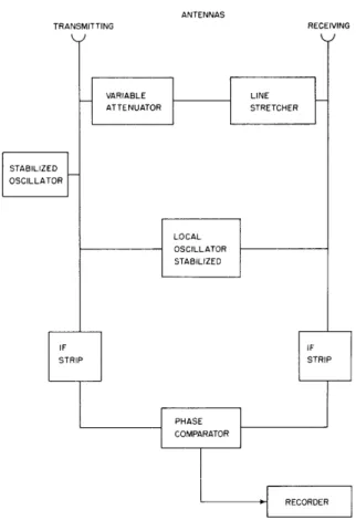
An X-band radar is being set up to investigate these fluctuations. On account of the nature of the required data, the test must be run for sustained periods of time, the final experiment calling for one week of continuous operation. The proposed system will utilize continuous-wave operation with balanced spillover, as shown in Fig. VII-3. A passive reflector will be located one mile away. To minimize spillover fluctuations and to avoid phase errors caused by a relative motion between the antennas, the transmitting and receiving antennas will be rigidly mounted 5 feet apart. A provision will also be incorporated in the mounting system to allow the antennas to look in a direction where
ANTENNAS TRANSMITTING RECEIVING VARIABLE LINE ATTENUATOR STRETCHER STABILIZED OSCILLATOR LOCAL OSCILLATOR STABILIZED IF IF STRIP STRIP PHASE COMPARATOR RECORDER
Fig. VII-3. Proposed system for measuring phase.
nulling, was only 25 db down from the transmitter signal level. Because the computed received signal level will be approximately 75 db down, the spillover balancing arrange-ment will be needed to gain another 60 db of isolation.
The use of a phase-locked stabilized klystron (1) for the transmitter (stabilized in frequency to two parts in 109) was deemed necessary for several reasons. Foremost among these was that frequency stability was required for the spillover cancelling system so that the attenuator and phase shifter need only be adjusted once during the test. Also, any variation in transmitter frequency would introduce undesired phase shifts between the direct signal and the received signal. A second stabilized oscillator will also be used for the local-oscillator signal.
V. J. Bates
References
1. Quarterly Progress Report, Research Laboratory of Electronics, M.I.T., April 15, 1956, p. 3 7.