Assessment and Preliminary Model Development of Shape Memory
Polymers Mechanical Counter Pressure Space Suits
By
MASSACHUSTT NSTUT Brian Wee
Submitted to the
NJ Z 21/
3
Department of Material Science & Engineering L
In Partial Fulfillment of the Requirements for the Degree of
L
R
FB IES
Bachelor of Scienceat the
Massachusetts Institute of Technology May 2013
C 2013 Brian J. Wee. All rights reserved.
The author hereby grants to MIT permission to reproduce and to distribute publicly paper and electronic copies of this thesis document
in whole or in part in any medium no known or hereafter created. Signature of Author:
Department of Material Science And Engineering May 15, 2013 Certified by:
Dava Newman Professor of Aeronautical ld Aerospace Engineering Thesis Supervisor
/V /
Niels Holten-Andersen Professor of Material Science and Engineering Thesis Supervisor Accepted by:
I
r ! ! Jeffrey C. GrossmanProfessor of Material Science and Engineering Undergraduate Committee Chairman
Assessment and Preliminary Model Development of Shape Memory
Polymers Mechanical Counter Pressure Space Suits
By Brian Wee
Submitted to the Department of Material Science & Engineering On May 15, 2013 in Partial Fulfillment of the
Requirements for the Degree of Bachelor of Science in Material Science & Engineering
ABSTRACT
This thesis seeks to assess the viability of a space qualified shape memory polymer (SMP) mechanical counter pressure (MCP) suit. A key development objective identified by the International Space Exploration Coordination Group, the development of a superior space suit with greater mobility and environmental robustness is necessary to support long-range human space exploration, specifically a mission to Mars. Conceptualized in 1971, a spacesuit utilizing MCP would fulfill these goals but its development was halted due to inadequate mechanical analysis and material limitations at the time. Since then, new active materials have been assessed to potentially further the development of a space qualified MCP space suit, which include
quantitative thresholds for minimum pressure production, durability, pressure distribution, mobility range, and ease of garment donning and doffing. Guided by these criteria, a SMP biaxial tubular braid applying MCP through active compression was designed and the prototype manufacturing processes were outlined. To predict the pressure production of this garment, the thermo-mechanics of a SMP was combined with the textile mechanics of a biaxial tubular braid and simulated within design parameter ranges consistent with the design criteria and practical considerations. The pressure production was controllable with the design parameters SMP elastic modulus, garment radial deformation, textile fiber spacing, and operational temperature.
Assuming reasonable model accuracy, a SMP garment could achieve the necessary pressure production for a space qualified MCP suit, however, the durability of such a garment would be
questionable considering the creep sustained from consecutive spacewalks of four to eight hours. Recommendations are made for methods to increase model accuracy, suggested SMP actuation mechanisms, and alternative textile architectures.
CONTENTS
Abstract List of Figures List of Tables 1 Introduction 1.1 M otiv ation ... 2 Mechanical Counter Pressure Suit2 .1 O v erv iew ... 2.2 Principle Design Criteria ... 2.3 Garment Engineering Design...
2.3.1 Constituent Material Selection... 2.3.2 Material Form and Textile Architecture Selection... 2.3.3 Bi-Axial Tubular Braid Active Compression Concept... 2.4 M anufacturing...
2.4.1 Monofilament Extrusion... 2.4.2 Tubular B raiding... 3 Shape Memory Polymers
3 .1 O v erview ... 3.2 Program m ing... 3.3 Shape Memory Thermodynamics...
4 Shape 4.1 4.2 4.3 4.4 5 Model 5.1 5.2
Memory Polymer Characterization
Sam ple Preparation... Differential Scanning Calorimeter... Dynamic Mechanical Analysis... Uniaxial Testing with Environmental Chamber... Theory
T heory Synthesis... Shape Memory Polymer Thermo-Mechanical Theory... 5.2.1 E lastic M odulus... 5.2.2 Accumulated Irrecoverable Strain ... 5.2 .3 C ycle L ife... 5.2.4 Other Considerations... 2 5 5 6 6 7 7 8 10 11 11 11 12 12 13 13 13 14 15 15 15 16 16 17 17 17 17 18 18 19 20
5.3 Textile Architecture Model... 5.3.1 Model Assumptions... 5.3.2 Textile U nit C ell... 5.3.3 Textile Unit Cell Mechanics... 5.3.4 Textile Structure Mechanics...
5.4 M odel Synthesis...
6 Shape Memory Polymer Characterization
6.1 Differential Scanning Calorimeter...
6.2 Dynamic Mechanical Analysis...
6.3 Uniaxial Testing with Environmental Chamber... 7 Model Results and Discussion
7.1 Combined Pressure Production Model...
7.2 Accumulated Irrecoverable Strain Model...
7.3 Parameter Optimization... 21 21 22 23 24 25 26 26 28 29 30 30 32 33 8 Moving Forward 34 8.1 Key Challenges...-- 3 8.2 R ecom m endations... 35 9 Final Conclusions 36 9.1 C ontributions... ... 37 10 Acknowledgments 37 References 39 Appendix 42
List of Figures
Figure 1: Model of MCP pressure vessel... 9
Figure 2: Biaxial tubular braid... 12
Figure 3: SMP programming... 14
Figure 4: Single fiber extrusion assembly... 16
Figure 5: Textile unit cell... 22
Figure 6: Textile elastic modulus vs bias angle... 25
Figure 7: DSC SMP sample full temperature range scan... 27
Figure 8: DSC SMP sample temperature range near glass transition ... 27
Figure 9: DMA SMP sample extension vs temperature... 28
Figure 10: DMA SMP sample Log(E) vs Tg/T... 28
Figure 11: DMA SMP sample isothermal isothermal strain to failure... 29
Figure 12: DMA SMP sample isothermal stress evolution over time... 29
Figure 13: Parameter planes of SMP textile pressure production model... 31
Figure 14: Accumulated irrecoverable strain over cycles... 32
Figure 15: Strain optim ization ... 33
Figure 16: Physiologic temperature zones... 35
List of Tables
Table 1: Primary evaluation criteria for a space qualified MCP suit... 8Table 2: SMP typical material property ranges... 14
1
Introduction
To further advance long-range human space exploration mission, the development of a superior spacesuit is a key-supporting objective agreed upon by seven space agencies of the International Space Exploration Coordination Group ("The Global Exploration Roadmap" 2011). This spacesuit is required to significantly improve high performance mobility and environmental robustness, increasing the safety of astronauts during extra vehicular activities (EVAs), while having less mass than the current spacesuits. One promising option that would fulfill these goals is the development of a spacesuit utilizing the theory of mechanical counterpressure (MCP). Instead of using a gas as a pressurant, a MCP suit uses elastic tension to mechanically apply counter pressure on the subject's skin, likened to a "second skin". Though a Space Activity Suit implementing MCP was designed in 1971, the project was never able to reach operational capability due to technologic and funding limitations. Given current advancements in computer generated biomechanical simulations and novel materials the development of a space qualified MCP suit is underway (Newman et al 2007; Meyen et al 2011; Holschuh et al 2012).
This thesis work is to explore the development of a shape memory polymer (SMP) MCP suit by outlining the design requirements of a space qualified MCP suit, understanding SMP thermo-mechanic behavior, and developing a model to adequately predict the pressure production of a SMP MCP textile.
1.1
Motivation
In 1967, NASA scientists tested nine chimpanzees to observe the physiological effects of sudden exposure to a near vacuum and the results of the study were sobering. All nine subjects lost consciousness within seconds and one subject died within 90 seconds of exposure (Koestler et al 1967). Tragically, four years later, these effects of depressurization were confirmed on humans when three cosmonauts lost their lives within minutes after a cabin vent valve malfunctioned and the cabin rapidly depressurized (Ezell and Ezell 1978). Acknowledging the dangers of space exploration and the necessity for EVAs for deeper human space exploration, space programs have invested heavily in developing a spacesuit to adequately protect the safety of astronauts.
Though many improvements have been made to the spacesuit since Alexei Leonov's first spacewalk, the underlying mechanism of gas pressurization has not changed, along with the limitations it presents (Portree and Trevino 1997). Current gas pressurized spacesuits have three inherent weaknesses. First, a puncture for any reason leads to rapid depressurization and ultimately the astronaut's death. Second, gas pressurized suits limit joint mobility, particularly complex movements involving joints with three degrees of freedom. Pelvic joints responsible for balanced locomotion are limited, making walking challenging, and fine motor control in a pressurized suit is greatly diminished (Annis and Webb 1971). These disabilities prevent astronauts from physically completing mission tasks and put the astronaut at risk of overexertion even during basic locomotion. Lastly, current spacesuits are extremely massive, with a mass of 117.6 kg. Each astronaut has different suits for launch and reentry, which adds a significant mass and volume that must be launched with every mission for all astronauts (Judnick 2007).
2
Mechanical Counter Pressure Suit
2.1
Overview
As an alternative to the gas pressurized suit, Paul Webb and James Annis published a report outlining the development of a new type of pressure suit design known as a space activity suit (SAS), a spacesuit utilizing MCP. The use of mechanical pressure yields several advantages over the current spacesuit design. First, the use of MCP eliminates the risk of suit depressurization from small punctures where a rip in a MCP Suit would only depressurize the local region near the rip. Second, Webb reported substantial increases in mobility and fine motor control. On average, the SAS retained 71% range of motion in joints and subjects reported walking was largely unencumbered and did not feel unbalanced during the test. Also, fine motor control with MCP gloves were far superior to pressurized gloves, performing at 77.7% of barehanded capacity compared to 32% in the fine motor control tests (Annis and Webb 1971). Third, the mass of the tested SAS was 17.9 kg compared to the 55.3 kg mass of the current spacesuits (Annis and Webb 1971; Thomas et al 2012). This is advantageous from an engineering and economic perspective considering the average payload cost per kilogram is reported to be $4,300 to $40,000 and the average cost of an EMU is estimated at $12,000,000 (Fultron 2002;).
Though Webb's report proved his SAS to be physiologically effective, unfortunately, the development of the SAS was undermined by problems stemming from limitations in technology an lack of funding. In his conclusion, Web stated,
"...there remain many problems to be solved, [and] they are principally
mechanical in nature. It has been suggested that solution of the mechanical problems, combined with careful tailoring based upon biomechanical analysis, plus the development of specific elastic fabrics, could eventually lead to a
space qualified version of the SAS," (Annis and Webb 1971 pg. 95).
Since then, computers have significantly advanced computational analysis and innovations in material chemistry leading to the discovery of materials with superior strength and extensibility. Recent research efforts led by MIT's Professor Dava Newman have moved the concept closer to reality. Analyzing computer generated biomechanical simulations, Wessendorf and Newman quantified skin-strain field lines of non-extension, minimum compression and minimum tension for a human during movement (Wessendorf and Newman 2012). These lines of non-extension have been used as the underpinnings for the development of a functional space qualified MCP
suit named the BioSuitiM (Bethke 2005).
2.2
Principle Design Criteria
To be considered a viable alternative to the current spacesuits, a MCP suit must achieve the primary functions and match the performance of the current spacesuits. The principle driving performance criteria to consider a MCP suit space qualified are summarized in Table 1.
Table 1: Primary evaluation criteria for grading a MCP suit space qualified.
Suit Function Requirement
Continuous fabric tension applying at least 29.6 kPa of pressure at Pressure Production body surface. (Judnick 2007)
Consistently apply 29.6 kPa for at least 125 consecutive cycles (Barton
1999)
Pressure Distribution Distribute pressure evenly, with no more than 20 mmHg spatial variation in pressure (Bethke 2005)
Mobility Allow full unsuited range of lower body joint rotations.
The minimum pressure production required to be space qualified is 29.6 kPa as this is consistent with the operating pressure of the Enhanced EMU, the current standard spacesuit (Thomas 2012). Assuming a thin-walled cylindrical structure, a minimum internal hoop stress of the pressure garment can be quantified using Eq. 1 using the model in Figure 1:
P r F T
-b - b - -b I - b (1)
Rwd
b
P
Figure 1: Model of an MCP cross section assuming a thin-walled pressure vessel (Holschuh et al 2012)
where a0 is the garment's hoop stress, P is the counter pressure, r is the local limb radius, b is the
material thickness, 1 is the axial length of the cylinder, F is the total circumferential force acting tangentially on the pressure vessel, and T is the wall tension (defined as the total circumferential force extended along the entire radial thickness). To maintain compliance with the "second-skin" design, the maximum desired spacesuit thickness is 5 mm (Judnick 2007). As limbs of smaller radii require a lower active pressurization, the largest limb radius, the upper thigh, must be considered. For the 9 5,h percentile male, this value is approximately 10.7 cm (Judnick 2007).
With these considerations, the pressure production of the MCP spacesuit translates to a minimum active hoop stress of 0.633 MPa or wall tension of 31.65 N/cm 2 (Holschuh et al 2012).
As well as producing above a minimum pressure threshold, the MCP suit must produce this pressure reliably for the mission duration and consistently over its operational life. A typical spacewalk lasts between 4 to 8 hours, limited to 8 hours due to the EMU's life support. Additionally, assuming a 500 day surface mission to Mars, a spacesuit may be commissioned
between 125 to 333 EVAs (Barton 1999). In summary, the suit must maintain the minimum pressure production consistently and reliably over 125 to 333 cycles of 4 to 8 hours.
Another important design consideration is the pressure distribution of the MCP suit. Even if the suit produces an adequate overall pressure, local zones of low pressure cause inconsistencies of circulation and thus uneven pressure distribution is life threatening. In regards to quantified threshold measure of this criteria, Bethke has reported there should be no more than a 20 mmHg or 2.66 kPa differential in pressure at any given point throughout the MCP suit (Bethke 2005).
One of the noted objectives in developing a superior MCP suit, a space qualified MCP suit should allow full range of motion of lower body joints such that walking is unencumbered. In Webb's initial study on the development of a MCP suit, Webb reported subjects wearing his SAS retained an average 58% and 82% of their range of motion of the knee and foot joints respectively (Annis and Webb 1971). It is this researcher's belief that a full range of motion will never be possible as imperfect suit contact with the wearer's skin will cause shear deformations, resulting in some loss of range of motion.
The last principle criteria for consideration is the ability of the wearer to don and doff the suit by themselves and do so within a reasonable time period. Webb's study mentioned improvements were needed in methods for donning and doffing a MCP suit as donning and doffing the tested SASs was a time conusming process and required the assistance of other people (Annis and Webb 1971). Bethke identifies 10 minutes as a practical amount of time to don and doff a space qualified MCP suit and should only require the efforts of the wearer (Bethke 2005).
2.3
Garment Engineering Design
Three components of a MCP garment's design are identified which control the mechanical performance of the garment: the mechanical behavior of the constituent material, the form the constituent material takes, and the textile architecture of the garment.
2.3.1 Constituent Material Selection
Knowing the minimum stress/tension characteristics necessary, the list of suitable materials for MCP suit development is significantly constrained. In this list, active materials are of particular interest as their potential to strategically augment wearable garments has been highly lauded. Reviewing typical documented values for maximum stress and active strain, Holschuh studied the current state of an array of active materials, grading their viability for the MCP suit development endeavor. SMPs were given the highest grade, able to produce high levels of stress, sustain large deformations, and had multiple actuation mechanisms, and accepted for further study (Holschuh et al 2012).
2.3.2 Material Form and Textile Structure Selection
In addition to the constituent material, the selection of a textile architecture in which the material is embedded is critical to the garment's mechanical performance. Holschuh et al assessed a MCP garment made of SMP would benefit from using a larger diameter fiber instead of a yarn composed of smaller diameter fibers, as the active response of a SMP scales with the fiber diameter. Using this form, Holschuh et al asserts a braided or interlinking mesh architecture would achieve compression by utilizing the SMP's capabilities to recover large deformations (Holschuh et al 2012).
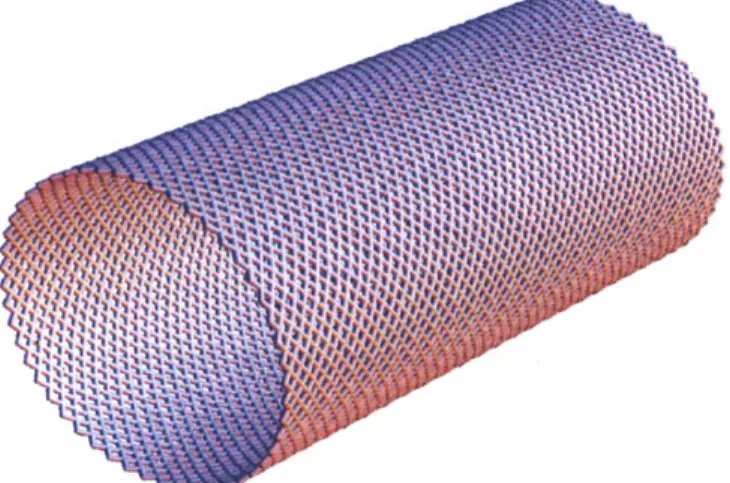
2.3.3 Bi-Axial Tubular Braid Active Compression Concept
The concept of this design uses a cylindrical biaxial braided architecture to create radial compression through changes in the cylinder radius. This structure is illustrated in Figure 2. In a passive state, the garment is rigid and form fitting to the astronaut's physique, easily donned and doffed. Upon activation, the garment will attempt to shrink significantly, producing significant compression on the astronaut's skin.
Figure 2: Model of biaxial tubular braided textile
2.4
Manufacturing
2.4.1
Monofilament Extrusion
A thermoplastic SMP monofilament may be extruded using standard extrusion procedures. The most common assembly is to use an extruder fed into a water bath, profiled with a laser, and wound into a spool using a windup unit. The standard procedure to extrude a polymer fiber in this assembly is used, as the following:
(1) SMP pellets are fed into the hopper of single screw extruder, where it is heated to the appropriate processing temperature.
(2) The SMP melt is pushed through a die into a fiber and quenched in the water bath. Note there are rollers at water level to ensure the fiber remains submerged as it cools.
(3) Exiting the bath, the fiber's dimensions are measured using a laser to ensure consistency of desired dimension.
(4) To maintain continuous fiber extrusion, the fiber is drawn with a windup unit and spooled.
The temperature zones within the extruder must remain consistent to minimize turbulent viscous flow and the screw rotation and windup rate must be synced to maintain continuous flow and a consistent desired fiber dimension.
2.4.2
Tubular Braiding
The common industrial practice to manufacture a tubular braid is to use a circular braiding machine wrapped around a core, which is later removed after the braiding process. However, this process has a number of limitations. Circular braiding machines are limited to a certain number of fiber lines it can weave and the majority of equipment is not designed to handle monofilament thicker than 1 mm. Also, the process is material exhaustive, as each fiber line requires an individual separate spool. An alternative manufacturing process is to 3D print the SMP garment. Recent innovations in 3D printing have opened the possibility of 3D printing complicated textile structures. However there are several limitations and challenges associated with this processing technique. Currently, standard 3D printers are designed to only handle a limited number of plastics. The spools of material are outfitted with a programmed microchip to communicate the current capacity and operating conditions of the spooled material to the printer so using a non-standard polymer would require programming a microchip. Regardless of the process, there is no standard method to prototype a SMP textile.
3
Shape Memory Polymers
3.1
Overview
SMPs are a family of polymers with the ability to "memorize" a permanent shape, able to recall and return to this shape given a stimulus. The shape memory effect is typically thermally-induced but other actuation mechanisms, such as electrical current, mechanical pressure, and light, have been demonstrated by incorporating indirect thermal actuation mechanisms or other reversible reactive molecular switches (Behl and Lendlein 2007; Liu et al 2007; Pretsch 2010). In terms of mechanical behavior, the typical ranges of the material properties of SMPs are
Table 2: Material property ranges of shape memory polymers (Lin et al 2007)
Material Property Typical Values
Elastic Modulus < > Tirns, Trans, 0.01 - 3 GPa 0.1-10 MPa
Maximum Strain Up to 800%
Density 0.9 1.1 g/cm3
Coefficient of Friction -0.5
Poisson's Ratio -~0.45 - 0.5 (Gall et al 200.2)
Processing Conditions <200' C, low pressure
Cost <$10/lb
3.2
Programming
To program and utilize the shape memory effect, a simple three-step process is needed. First, by conventional processing (e.g. extrusion, injection molding), the SMP melt is cooled below its highest thermal transition (Tpem) and forms into an initial shape, which is its permanent shape, A. Next, the SMP may be deformed at temperatures between Tperm and its second highest transition temperature (Ttrans). If the SMP is cooled below Ttrans while still deformed, the SMP will stabilize and hold the temporary deformed shape, B, as long as the temperature stays below Ttrans. Finally, if the polymer is heated above Ttras, the polymer will recover its initial shape A. This process may be repeated several times with different temporary shapes but always recovering to shape A. This process is illustrated in Figure 3.
[A
---
B
l
V
L
TgFigure 3: Process of programming a SMP with permanent shape A. Step 1: the temperature is raised above Tg and the shape is deformed to shape B. Step 2: still deformed, the temperature is lowered below Tg and shape B is stabilized. Step 3: the temperature is raised above Tg and the SMP returns to shape A. This process is repeatable with different shape B's.
3.3
Shape Memory Thermodynamics
The SMP's shape memory ability is not an intrinsic property of the polymer but a result of the polymer morphology and/or specific processing. There are two types of SMPs: thermoset and thermoplastic SMPs. Both SMP types have two main features of their morphology: netpoints where the SMP is chemically or physically cross-linked and stimuli-sensitive switching segments. Thermoset SMPs are chemically cross-linked and generally have higher stiffness and lower strain capabilities than thermoplastic SMPs. Thermoplastic SMPs are physically cross-linked SMPs and are generally easier to reshape than thermoset SMPs (Behl 2007).
The shape memory effect of thermoplastic SMPs may be explained by the thermodynamics of its chains. Thermoplastic SMPs are typically block copolymers with at least two phase-segregated domains. Domains related to Tperm act as netpoints and are known as hard segments. Domains related to Ttrans act as molecular switches and are known as switching segments. The netpoints are caused by physical entanglement of the polymer chains as the chains favor a strongly coiled conformation, its state of maximum entropy. When the operating temperature is above Ttrans, the switching segments are flexible and the chains exhibit entropic elastic behavior and may stretch. When the temperature is cooled below Ttrans, the chains stabilize wherever they are positioned. However, if the chains are deformed causing the coils to straighten, the netpoints will seek to return to the state of maximum entropy due to the entropic penalty incurred if the chains are straightened. When the temperature rises above Tirans, the switching segments once again become flexible and the chains will recover the original shape (Lendlein 2002).
4
Shape Memory Polymer Characterization Testing
4.1
Sample Preparation
Test specimens were prepared from commercial thermoplastic shape memory polymer pellets, supplied by Manborui Material Technology. This SMP was intended for anti-counterfeit shape memory security labels. The pellets were extruded at 440' F in an extrusion assembly consisting
of a single screw extruder, water bath with rollers at water level, laser profilometer, and windup unit, pictured in Figure 4. The filament diameter was 2.6 +0.5 mm.
Figure 4: Fiber extrusion assembly at Univeristy of Massachusetts -Amherst including single screw extruder, water bath, laser profilometer, and windup unit.
4.2
Differential Scanning Calorimeter
A Differential Scanning Calorimeter (DSC) was used to observe the thermal transition temperatures of the polymer. The sample mass was 15.24 mg and the temperature was swept from 0 to 70 with a heating rate of 50 C/min. Additional samples were tested to confirm the glass transition temperature because the melting peak was close enough to the sample to muddle the
glass transition temperature range.
4.3
Dynamic Mechanical Analyzer
A Perkin Elmer Dynamic Mechanical Analyzer (DMA-7) was used to perform a dynamic
thermal scan in three ramps from 30' C to 40' C, 400 C to 500 C, and 50' C to 570 C with
heating rates of I' C/min, 0.50 C/min, and 0.10 C/min respectively. The size of the test specimen was approximately 18.87 mm long with a diameter of 2.62 mm. The purpose of this experiment was to determine the glass phase transition temperature and basic mechanical response of the polymer, which are relevant parameters to the model development seen below.
4.4 Uniaxial Testing Machine with Environmental Chamber
A Zwick/Roell Z010 Uniaxial Testing Machine with an Environmental Chamber was used to perform isothermal strain-to-failure, fixed strain stress evolution, and cyclic fixed strain stress
evolution tests. All test specimens were approximately 9 cm in length and the distance between grips was approximately 3 cm. The grips used were clamps and produced a compressive force of approximately 2.5 N when clamped. All tests were performed with a strain rate of 5 mm/min. The strain-to-failure test was tested at 550 C and was incomplete as the machine reached a maximum strain of 367% and the polymer did not fail. The fixed strain stress evolution test was tested at 55' C with a maximum strain of 15% and held for 30 minutes. The cyclic fixed strain stress evolution test was tested at 52' C raised to a maximum strain of 15%, held for 10 minutes, and repeated. The purpose of these experiments is to observe the fracture strain, stress evolution over time, and % irrecoverable stress of the holding strain accumulated over recursive cycles.
5
Model Theory
5.1
Theory Synthesis
Though there is no continuum mechanics model for an SMP textile, previous studies have indicated textile mechanics can be approximated by modeling the microscale forces within individual fabric unit cells and then relating these microscale forces to the total structural stresses (Kawabata 1973a; King 2005; Ji 2013). This suggests the thermo-mechanics of the SMP fiber may be coupled with an appropriate textile model to predict the mechanical behavior of a SMP textile.
5.2
Shape Memory Polymer Thermo-mechanical Theory
At this time, there is no generally accepted deterministic constitutive model to predict the thermo-mechanical behavior of SMPs for strains over 10%. As a result of the phase-separated morphology that gives SMPs their shape memory ability, SMPs exhibit atypical nonlinear
temperature dependent viscoelasticity and strong hysteresis, inconsistent with the traditional linear viscoelastic theory most polymers exhibit. Current approaches include multiplicative decomposition of the morphologic phases and modeled in finite element analyses (Baghani et al 2012). Fortunately, for the scope of this study, a constitutive continuum model is unnecessary because the garment functionality occurs within isothermal and fixed strain conditions thus only select variables that impact this scenario must be examined.
5.2.1 Material Property: Elastic Modulus
The mechanical properties of SMPs exhibit strong temperature dependence particularly near the SMP's Ttrans. Noted in Table 2, the elastic modulus of a SMP ranges on the order of GPa to MPa based on the temperature. Tobushi et al observed the elastic modulus was stable at temperature far from the SMP's Tg and followed a log linear with a window of temperatures near the Tg. He developed the following relationship:
Tg
E g e aT 1) (2)
where E represents the elastic modulus, Eg represents the elastic modulus when the temperature was Tg, and a is a material specific constant, citing a typical range between 34 and 45 (Tobushi 2000). The functional range of this relationship was within a specified temperature the glass transition region (Ttrans + T,) and outside this regime the parameter stabilized into constant
values.
5.2.2 Shape Memory Polymer: Accumulated Irrecoverable Strain
One measure of a SMP's durability is its accumulated irrecoverable strain. To its detriment, SMPs exhibit significant material fatigue under extended periods of deformation. During long durations of stress, SMPs accumulate irrecoverable strain, causing the material to sustain permanent irrecoverable strain. Tobushi et al developed a model to predict the ratio of irrecoverable strain to holding strain given a maximum holding time of 8 hours, expressed as:
S = = Sp 1 - e-(hs)) (3)
where Ep and Eh is the irrecoverable strain and holding strain, respectively. Sp, th, ts, and c denote
the saturated value of S, the holding time, the critical time before irrecoverable strain appears, and the time constant, respectively. Note if the holding time is longer than 8 hours, this model is no longer true and S increases dramatically. Dependent on whether in tension or bending, Sp, ts, and c are directly correlated with temperature. In tension, these values are defined as:
Sp = 0.04(Th - Tg) + 0.12
ts= -0.16(Th - Ty) + 2.7 (4)
c = -0.26(Th - Tq) + 6.6
where Th is the holding temperature and Tg is the glass transition temperature (Tobushi 2008). In this form, the irrecoverable strain rate can be expressed as a function of the holding temperature and holding time. If the SMP is held at a large strain such that a time-independent plastic strain forms, the accumulated irrecoverable strain may be written as:
ES = S(Ec + Ep) (5)
where s, s, and c, are the irrecoverable strain, creep strain, and plastic strain respectively (Tobushi 2001).
5.2.3
Shape Memory Polymer: Cycle Life
Another measure of the SMP's durability is the cycle life. Though there is no ubiquitous quantified measure for this, it is generally agreed the cycle life is defined as the number of thermomechanical recursive cycles a SMP can endure before material failure or loss of shape memory. A SMP's cycle life is highly variable dependent on the maximum strain and operating temperature of the cycle. Under low strains in both bending and tension, SMPs enjoy a high
degree of precision and durability with shape recoverability higher than 99% and a cycle life higher than 200 cycles (Lendlein; Pretsch). In bending, Lin completed 200 cycles of small angle bending and reported a loss of only 4% strain, cycling at T = Tg + 25' C (Lin). In tension, Tobushi tested samples at 20% at T = Tg + 20' C and observed very high shape recovery over 10 cycles. Testing a sample at 100% at T = Tg + 20' C, Tobushi observed the polymer had very poor shape recovery initially and began stabilizing with repeated cycles. After the 10 th cycle, the
irrecoverable strain was about 20% and the stress suffered by about 15%. His results for these experiments are shown in the appendix (Tobushi 2008). Additionally, Goo et al found higher actuation temperatures induce faster property degradataion as a result of rapid movement of molecular chains (Goo 2007). In conclusion, a SMP will maximize its cycle life if held under low strains and low temperatures.
5.2.4
Shape Memory Polymers: Other Considerations
Other considerations that impact the SMP performance are the SMP water vapor permeability, thermal expansion, and effects of long term strain storage. Hu et al demonstrates if a shape memory polymer has a high water vapor permeability, steric interactions between water and the SMP cause a large variability in mechanical behavior. To mitigate this effect, a hydrophobic membrane should be introduced to the SMP (Hu 2012). Also, SMPs experience volumetric thermal expansion with temperature change. In this design, the length of the fiber is fixed so the volumetric expansion will only affect the radius of the fiber. This effect is summarized as:
r= r 2* (aAT + 1) (6)
where r and ro are the radius at the heated temperature and stable temperature and a is the coefficient of volumetric thermal expansion. Also, Gunes reported thermal expansion has a significant negative effect on recoverable strain, dependent on the magnitude of temperature gradient in the shape recovery step, thermal expansion coefficient of the system, and level of recoverable strain (Gunes 2008). This is further evidence the SMP design should operate at lower temperatures. Another consideration is the effects of long term storage as the SMP MCP suits will be stored for long durations of time during space travel. Tey explores the effect of long
term storage of SMP foams and found poor storage attributed to a holding temperature close to the Tg of the SMP. Testing again under temperatures much lower than Tg, Tey found complete strain recovery after a hibernation period of two months and observed no clear hibernation effects (Tey 2001).
5.3
Textile Architecture Model
To describe the textile structure mechanics, the following systemic approach is used:
1. Identify a unit cell within the fabric and define all relevant parameters
2. Describe the internal force of the unit cell describing the deformations and interactions of the component fibers
3. Approximate textile forces by superimposing internal unit cell forces and relate these to the pressure production of the textile.
5.3.1
Model Assumptions
Three assumptions about the scope of the model are adopted to simplify this analysis. First, the model does not need to account for behavior associated with yarns. Because the textile is composed of a single fiber as opposed to a yarn composed of hundreds of smaller fibers, failure modes that cause abnormal mechanical behavior such as yarn breakage, unraveling of the weave, and yarn pullout are not within the scope of this analysis. Second, the model assumes the fibers may rotate at points of contact but no slipping occurs between fibers in contact with one another. Since fiber slippage dominates textile mechanics during the onset of textile failure, this effect may be ignored as the SMP garment design should never be operating near failure. The last assumption is the effects of bending on the stress production are negligible. The effects of bending on the mechanics of the textile are highlighted under low extensions but the scope of this study ignores strains under 10% and thus the bending stresses are ignored.
5.3.2
Textile Unit Cell
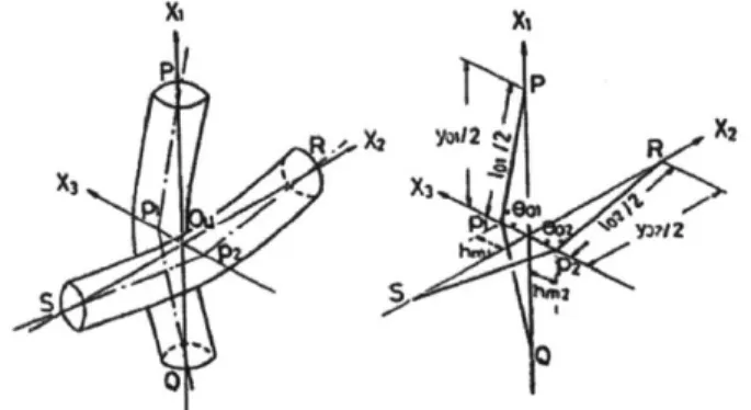
A unit cell is adopted from Kawabata's Biaxial Deformation theory, as depicted in Figure 5 (Kawabata 1973a). Two sets of fibers run along a set of intersecting neutral axes represented by lines PQ and RS called the warp (XI) and weft (X2) axes respectively. The orientation of these axes in respect to one another is a critical factor in the structure and the angle at which they intersect is called the bias angle (0b), typically ranging between 20' and 70' as delamination
Ai X, P 2 xX S . ,
Figure 5: Textile unit cell adopted from Kawabata's biaxial deformation theory (Kawabata 1973a)
occurs outside this range (Smith 2005). Fibers in each axis intersect periodically at point 0 where the center of the fibers are spaced at a fixed deflection length (h) from the yarn axis along the X3 axis in a given state passing through points pi and P2. If the system is modeled in cylindrical coordinates, the X3 axis is also the radial axis. The angle between the yarn axis and the X3 axis is denoted as 0. In Figure 5, the deflection of the warp axis is negative and the deflection fo the weft axis is negative. The respective sign alternates with adjacent units cells but the absolute deflection remains the same in a given state. The length of the fiber in the unit cell is denoted as 1. The spacing between each unit cell, the fiber spacing, is denoted as y. The fiber density, number of fibers per millimeter in a given axis, is denoted as n and equivalent to 1/y. This unit cell is superimposed in cylindrical coordinates equidistant from the longitudinal axis to create a bi-axial tubular braid.
To denote axis direction and deformation states, the subscript 1, and 2 following the defined terms denote values relating to fibers in the warp and weft directions, respectively, and the
subscript 0 denotes values in the undeformed state. The stretch ratio denoted as lf represents the ratio of the length of the fiber in the deformed state to the undeformed state (e.g. Af,1 = l/1) and ;Y represents the ratio of the length of the fiber spacing in the deformed state (e.g. AY = y/yo), analogous to the circumferential strain of the textile. Also, the deflection in the undeformed state, which is also the maximum deflection of h, is noted as hm. The stretch ratios are related to one another in the following expression:
- ((Ly) 2 +(2hm )2)
n =) (7)
( ) +(2hm)2
5.3.3 Textile Architecture Unit Cell Mechanics
Upon deformation, multiple internal forces are created within the yam. If a force is applied along the X3 axis, three forces are observed: a yarn tension acting along the central axis of the yams (F1), a compressive force acting along the X3-axis at he point of contact of the warp and weft threads (Fc), and a tensile force on the fabric along the co-ordinate axis (F) a force that may be translated into a force per single yarn end. Kawabata deduces the unit cell tensile force may be modeled as: F1 = 91(2,1) J1 _ 4---132 2 (8) hi= cs6)- ly11C11 (9) 0= ArcTan (2h) (10) 10 2hm (1 = cos(o) (12
91(Af,1) = riber * Efiber * L
)
(12)where function g1 (af,1
)
represents the mechanical behavior of the fiber, rf is the fiber radius, andEfiber is the fiber elastic modulus along the longitudinal fiber axis measured in kgf/mm2
as the nonlinearity is heavily dominant during polymer yielding and the model operational range is constrained to minimize polymer yielding as seen below. When calculating true strain, (Xf -1) is replaced with Ln(if). Though Kawabata's model was designed for a flat braided surface, this relation may be applied to tubular braid because the parasitic effect of garment's curvature on the circumferential force is negligible, a total effect of less than 2%.
5.3.4
Textile Architecture Structure Mechanics
Superimposing the internal forces to create a textile structure, the total internal structural force is translated into a compressive stress. The deformation of the garment is denoted as Xr which relates to the yarn deformation expressed as:
A2-tan(b,o)2 A2+1
= 1+tan(Ob,o)2 2 (13)
Using Equations X and X, the fiber deformation can also be expressed in terms of garment deformation expressed as:
2
(1)2 +(2hm)2
In the scenario, which the garment is expanded but the height of the garment is fixed, the bias angle increases proportionally to the change in radius:
tan(&b) = Ar * tan(Ob,o) = Ar (15)
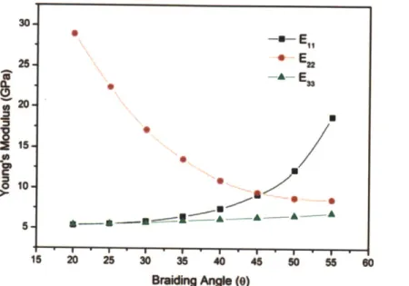
where 01 is the bias angle in the deformed state. Mentioned earlier, the bias angle is a critical component of the textile mechanical behavior. The transverse elastic modulus of a braided
this change in elastic modulus is demonstrated in Figure 6. The effect on the elastic modulus is expressed as a strain dependent multiplicative factor:
I
ii
30- 25- 20- 10-15 20 25 30 35 40 45 50 55 0 Braiding An e (0)Figure 6: Elastic modulus along each axis of a tri-axial braid dependent on bias angle (Ji 2013)
CE = 1 + Ef (1 - UEf) (16)
where cE is the bias change factor, E and Eo are the modulus of the textile in the deformed and undeformed states, u is the Poisson's ratio, and Ef is Af - 1. The effective modulus is expressed as E = EO * CE, where Eo is the elastic modulus in the undeformed state. The total circumferential force of the textile is found by multiplying this value with the number of unit cells in the structure, expressed as:
Ftotai = F1 * cells * cE (17)
(18)
cells = (2"rrMCp*n)2 MCP* ) = JnrMCP * n * IMCP *
Ftotai = FlirMCP * n 2 * MCP * Af * CE
where Ftotal is the total circumferential force and IMCP is the length of the MCP garment. The structure's pressure production can then be expressed as:
E E
En
Uy = Ftotal (19)
b 1MCP
where b is the material thickness.
5.4
Model Synthesis
With the variability and considerations in mind, a model to synthesize the mechanics of the bi-axial tubular braid made of SMP may be developed. To simplify the analysis and model symmetric fatigue, two assumptions are made: the initial bias angle of the garment is +45' and there is an equal number of weft and warp yams. Synthesizing equations 2, 4, and 5, the unit cell circumferential force of the SMP garment is calculated as:
F1 = rc2 (Ea -1) Ln(f) 1 - (20)
where rfiber is from Equation 4 and ro of rfiber is the radius of the polymer at the glass transition temperature. In the design of this textile, the independent variable parameters which can be
easily observed are T, 2
r, Eg, and n. See Appendix for full equation form.
6
Shape Memory Polymer Characterization Results
6.1
Differential Scanning Calorimeter
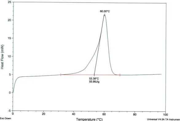
As seen in Figure 7, the DSC found a sharp endothermic peak at 60' C consistent with a melting temperature. The problem with this SMP was the Tg was close to the Tm resulting in peak overlap. The DSC was ran again near the glass transition range and the change in endothermic flow was measured and compared to accurately find the Tg. As seen in Figure 8, the Tg was determined to be near 50.3' C.
E 10- 5- 0--5 0 20 40 60 80 100
Ex Down Temperature (*C) Universal V4.5A TA Instruments
Figure 7: DSC of SMP sample from temperature range 00 C to 700 C. Tm is 60' C. Tg is unclear.
15 50.37*C 10 46.98*C(I) 44.91*C E 5-(D 20 25 30 35 40 45 50 5
Exo Down Temperature (*C) Universal V4.5A TA inetnunents
6.2
Dynamic Thermal Scan
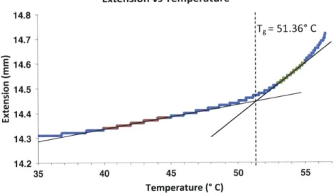
To confirm the phase transition temperature and observe the temperature dependence of the elastic modulus, a dynamic thermal scan using a DMA was used. Measuring the specimen change in extension with the temperature in different phases, the glass transition point was approximately 51.360 C, as seen in Figure 9. The elastic modulus was found by sweeping the storage modulus and loss modulus over the relevant temperature range. The elastic modulus temperature dependence was consistent with Tobushi's findings however a significant loss of modulus was observed as the temperature approached the specimen's Tm, in Figure 10
Extension vs Temperature 14.8 :Tg 14.7 E14.3-E .2 14.5 4X 14.4 U.' 14.3 14.2 35 40 45 50 Temperature (" C)
Figure 9: DMA Extension vs Temperature. Using the extensio regions, the Tg is pinpointed as 51.36' C.
Elastic Modulus vs Temperature
0 -j 8.6 8.5 8.4 8.3 8.2 8.1 8 7.9 7.8 I -I I I I I I
'I
= 51.36* C 55 n rate in known 0.985 0.995 ' 1.005 1.015 1.025 1.035 1.045 1.055 Tg/T6.3
Uniaxial Loading Tests
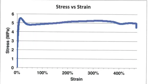
To measure the isothermal stress strain response, the sample was tested with a uniaxial loading test machine with an environmental chamber. Figure 11 is the full range of strain the machine could test. Unfortunately, though the polymer necked and plastically deformed significantly, it did not fracture after 467% strain. Figure 12 is the isothermal stress evolution after a long period of time. As seen, the viscoelastic properties of the polymer are highlighted with an initial peak in stress but the SMP sample slowly relaxes to -0.5 of the max stress.
Figure 11: Uniaxial test at 550 C, strain to failure. The test was incomplete as the polymer had a fracture strain higher than the operating limit of the machine.
Figure 12: Uniaxial test at 55* C, 15% fixed strain stress evolution over time. The viscoelastic effects are observed as the stress initially peaks and stabilizes over time.
7
Model Results and Discussion
7.1
Combined Pressure Production Model
The synthesized model was tested with parameter ranges consistent with typical SMP material property values and the MCP design considerations. The maximum value of rfiber and b was 1.25 mm and 5 mm, respectively, to preserve the design goal of a 5 mm thick garment. To accommodate larger limbs, the largest radial limb thickness is used so rMcP was 10.7 cm. Mentioned earlier, the initial bias angle 0
b,O is set as 45'. The initial deflection hm,o was equal to radius of the fiber, 1.25 mm. From Table X, the typical Poisson's ratio of a SMP is between 0.4 and 0.5, so a value of 0.45 was used. As reported by Gunes, the volumetric coefficient of thermal expansion was typically 1.8 x 10⁴ 1/K. The design variables that could be modulated during manufacturing or operation were the fiber modulus, holding temperature, yam spacing, and garment strain. Using the typical elastic modulus values from Table 1 and using equation X for the minimum and maximum values, the Eg values ranged from 1 to 173 MPa. To minimize, thermal degradation but retain shape memory ability, the temperature range of Tg/T was 0.95 to 1.0 where the Tg was set as room temperature, 293 K. To minimize plastic deformation of the SMP, 2f was confined to a range of 1.1 and 1.5 equivalent to a Ar range of 1.2 to 2.03. To demonstrate the effect of different yam spacings, the yam spacing ranged from 5 to 12.5 mm equivalent to a fiber density of 0.2 to 0.08 ends per mm. These values and ranges are
summarized in Table 3.
Table 3: Values and ranges for model parameters used in pressure production simulation consistent with design goals
rfiber 1.25 mm rMcp,1 10.7 cm
Ob,O 450 b 5 mm
a {34,45}, 40* hm,o 1.25 mm
v {0.4,0.5}, 0.45* a 1.8 *104 1/K (Gunes 2008)
,f
I Ar {1.1, 1.5}, {1.2, 2.03} Eg, Log(Eg) {1, 173} MPa, {6, 8.236} Tg/T, Tg {0.95,1.0} , 273 K y, n {5, 12.5} , {0.2, 0.8}
Using these boundary conditions, Figure 13 illustrates the minimum values of all 4 parameters necessary to produce the baseline pressure of 0.633 MPa. The simulation suggests a SMP garment is achievable within the range of parameters. The maximum pressure production occurred when the strain, elastic modulus, and fiber density was maximized and temperature was minimized. However, these parameter maximizations conflict with the design goals. Importantly, SMPs with higher elastic moduli tend to have poorer shape recovery and higher strains are attributed to larger amounts of permanent plastic deformation to SMPs, conflicting with the design goal of durability. Secondary considerations, maximizing fiber density increases the mass, conflicting with the design goal of mass minimization and operating at temperatures near Tg run the risk of decreasing shape recovery.
2 fbers/cm 1-.3 ners/cn, Log( E) 1 fiber/cm 6.5 20% --- 0.95 :- 0.9 0.8 fibers/cm 60% 0.9 Strain (Ar) 80% 100% T
Figure 13: Planes representing the material parameter values that produce a pressure production of 0.633 MPa. Anything above the planes is producing more than 0.633 MPa.
The combined model behavior is consistent with the model behavior of the individual elements. As seen in Figure 14, Log(Eg) is linearly correlated to Tg/T consistent with the Tobushi material parameter model. As seen in Figure 15, the pressure production is exponentially correlated to the garment strain consistent with the Kawabata circumferential force production model. Kawabata's model demonstrates high confidence in predicting internal forces uniaxial extension using several different materials with the exceptions of low extensions, where bending plays a more substantial role than suggested in the model and in the yield region of polymers where plastic deformation results in a non-linear tensile response. Both these exceptions may be ignored, as the
operating ranges were intentionally selected to avoid these conflicts. Assuming the SMP material behavior has been adequately quantified, it is a reasonable hypothesis that this model is a good approximation of the pressure production of a SMP textile.
7.2
Accumulated Irrecoverable Strain Model
To assess durability, the accumulated strain, variable with time and temperature, was modeled. As seen in Figure 14, the ideal temperature was equal to Tg. However, even at a holding temperature of Tg, the accumulated irrecoverable strain is significantly high. After 50 cycles, the accumulated irrecoverable strain is ~85%. On a better note, the model suggests if the holding time is less than 2.7 hours and the holding temperature is at Tg, there is no irrecoverable strain
accumulated and the SMP may be used for the entirety of its cycle life.
Accumulation of Irrecoverable Strain over Recursive Cycles
100%-8 hours 80% 7 hours S60% 6 hours 8 O 40%/-'o 5 hours 20% 3 hours 0% 1 5 10 15 20 25 30 35 40 45 50 # of Cycles
Figure 14: Accumulated Strain vs # of Cycles. The colors represent hours and the series of colors represents the holding temperature. Bottom to top, the respective holding temperatures are Tg, Tg + 5 K, Tg + 10 K
7.3
Parameter Optimization
Considering both simulations, the optimal temperature is Tg. Also, a maximized fiber density is desired to maintain even pressure distribution but a density of 0.2 fibers/mm is impractical as it is the maximum theoretical fiber packing, so a density of 0.133 fibers/mm is optimal. Using these parameters, the sensitivity of the elastic modulus and garment deformation was assessed. As seen in Figure 15, the optimal garment deformation was 1.44, equivalent to a fiber strain of 22%. Using the optimal parameters, the elastic modulus produces enough pressure throughout the range and thus the minimum elastic modulus may be used to maximize cycle life.
Ar Parameter Optimization: Double Partial Derivative of Pressure Production in respect to Ar
Figure 15: Double derivative of pressure production in respect to garment deformation. The incremental changes peak at 4,= 1.44.
8
Moving Forward
8.1
Key Challenges
To further advance this study, several challenges must be overcome including prototype manufacturing, prototype and model evaluation, and prototype scaling.
Prototype manufacturing - A severe limiting factor is the absence of an easy method to manufacture a SMP textile. The use of industrial sized machinery is required to produce a textile with the number of fiber lines proposed and a significant amount of fiber must be produced in order to use the equipment. Even if enough fiber were produced, the machine may not be able to handle the fibers considering the proposed filament thickness is much thicker than industry standard. Customizing a 3D printer may be a more viable option but requires a programming a microchip for the SMP spool.
Prototype and Model Evaluation - To validate the conclusions of this paper, the model must be validated with experimental data. Accurately measuring the body surface pressure in hypobaric conditions remains a practical challenge. A test would require placing a prototype in a sealed hyperbaric chamber for 8 hours, observed by a flexible, flat pressure sensor. The chamber is subject to leaks and the sensor is subject to a degree of uncertainty as these types of sensors are notoriously sensitive to environmental variables such as humidity, temperature, wrinkling, and bending.
Prototype Scaling - Eventually, the sleeve is to be scaled to a full body SMP MCP suit, considerations for discrepancies in body radius and physiological temperature zones must be made. If the suit is strained at different amounts throughout the body, the pressure distribution will be uneven. Two possible solutions are to customize the radius of the suit for each subject to allow for consistent strain throughout the body and to modulate the actuation mechanism to allow for variable actuation depending on limb radius. As for differentiated temperature zones, Webb reported a large variation in the temperatures throughout the human body, pictured in
Figure 16, which would result in uneven actuation for a temperature-sensitive SMP (Web 1971). This temperature discrepancy can be mitigated by adding a significant layer of insulation between the body and MCP layer or by controlling the active compression for each zone using alternative actuation. W W 38 36 34 32 30 28 26 24 22 20 0 --RECTAL - CHEST - KIDNEY THG CALF -AMBIENT (room) 30 60 90 120 TIME-min
Figure 16: Temperature of different body zones (Annis and Webb 1971)
8.2
Recommendations for Improvement
In this section, several suggestions are offered to further the analysis of SMP's and improve the SMP garment design.
SMP Selection - The first recommendation is to procure an SMP with an indirect actuation
mechanism such as electrical current. Goo et al reported an increase in cycle life from 120 to 420 cycles with a strain of 60% using a conductive SMP by lowering the actuation temperature with a running current (Goo 2007). This would allow a lower operating temperature, limiting thermal degradation, and a controllable variable actuation mechanism, better suited when scaling into full suit development.
fanndn
-a o
Irrecoverable Strain Management - The second recommendation is to determine the effect of irrecoverable strain on the observed stress of the SMP and to find systems to mitigate accumulated irrecoverable strain. To determine the effect of irrecoverable strain on SMP stress will require running fiber stress and strain during recursive isothermal 8-hour cycles of fixed strain. Finding systems to mitigate accumulated irrecoverable strain may not be possible as this is an inherent property of viscoelastic materials and the issue is not the polymer but the length of the mission itself. One possibility is to overengineer the system and pre-strain the suit such that the suit will have so much irrecoverable strain following cycles will have a negligible increment of irrecoverable strain but still produce enough pressure.
Finite Element Analysis - The third recommendation is to use finite element analysis to refine the model and more accurately predict textile mechanical behavior. This would include developing garment radial displacement gradients and strain tensors for the garment and SMP. This is also challenging considering the three-dimensional nature of the model. The recommended program for this analysis is ABAQUS.
Alternative Textile Architectures - The final recommendation is to explore the use of alternative textile structures such as a reinforced composite or triaxial braid. The general concept is to increase the effective modulus of the SMP and limit the chain mobility of SMP to increase cycle life. Encapsulating the fiber may also provide a good way of insulating and controlling the SMP temperature (Masters 1996; Ji 2013).
9
Final Conclusion
This thesis aimed to assess the viability of a space qualified SMP MCP suit and found two key conclusions.
1. Based on the preliminary model, a SMP garment can sustain the minimum pressure production within the specified parameter ranges.
2. The theoretical accumulated irrecoverable strain suggests the length of missions is too long for SMPs to be used as a viable option for the development of a space qualified MCP suit.
In conclusion, SMPs may not be leveraged for the development of a space qualified MCP suit unless spacewalks are completed within 3 hours of actuation. The biggest practical challenge to continue this research is to develop accessible manufacturing processes for garment prototyping.
9.1
Contributions
This study makes contributions to several different fields of research including advanced
spacesuit design and novel textile mechanical analysis. The design was built primarily from key literature from Annis and Webb for advanced locomotion MCP suit design, Tobushi for SMP thermo-mechanics, and Kawabata for uniaxial textile mechanics. This thesis has been an exercise in novel textile engineering, using SMP actuation to apply MCP, and applying SMP thermo-mechanics to predicting the thermo-mechanics of a SMP MCP textile. It is my hope this study will encourage others to research other active materials for MCP suit designs and further investigate additional applications to leverage SMPs.
10
Acknowledgments
The thesis would not be possible without the support of Brad Holschuh, who acted as my direct supervisor and mentor. He gave me the opportunity to work on this exciting project and his guidance and infectious optimism throughout the endeavor has been invaluable. MIT Professor Niels Holten-Andersen and Professor Dava Newman acted as my thesis course advisors and their unwavering support and feedback on the technical structure of the thesis is greatly appreciated. UMass-Amherst Professor Daniel Schmidt and Professor Stephen Johnston are thanked for their indispensable technical support and expertise in polymer characterization and prototype
characterization testing. Manborui Material Technologies is thanked for supplying SMP sample material. Finally, I would like to thank my friends and family, particularly Sunny Wicks and Edward Obropta whose guidance and expertise in polymer characterization was indispensable.