by
Charles B. Fly
Submitted in Partial Fulfillment of the Requirements for the Degree of Bachelor of Science
at the
MASSACHUSETTS INSTITUTE OF TECHNOLOGY July, 1978
Signature of Author .;.-.-... ..- .... Department of Mechanical Engineering
Certified by... Thesis Accepted by..w 6... Chairman, .1... . . uly, 1978 Supervisor .. ~~ ...
Deparental Committee on Theses
ARCHIVES
L I71.70
BICYCLE POWERED WATER PUMP BY
Charles B. Fly
Submitted to the Department of Mechanical Engineering in July, 1978 in partial fulfillment of the requirements for the Degree of Bachelor of Science.
ABSTRACT
There is a need for pumping systems in underdeveloped countries that could produce several gallons per minute of water at up to 200 feet of lift. A double acting bicycle powered pump was built and tested to provide an economic
answer. The pump utilized a fluidic linkage between the
pump pistons to allow the pistons to be oriented
vertical-ly. This permitted direct connection of the pistons to the
surface through music wire drive cables loaded in tension with no down hole linkages or flexure.
The pump did not achieve design performance due to
dissolved air and fluid inertia effects in the fluidic
link-age. This led to increased seal drag resulting from flexure
achieved 65% volumetric efficiency at 24 RPM. It delivered
5 gpm at 55 feet of lift. Estimated efficiency was 40%.
The failure mode was analyzed resulting in a
recommend-ed improvrecommend-ed design for a single acting pump. This new pump
utilizes improved valving and a long stroke rolling diaphragm
to reduce cable loads.
A final discussion recommends the development of a
bicycle powered cable tool drilling unit to reduce the cost of drilled wells for the application of these pump units.
Thesis Supervisor: Professor David Gordon Wilson
ACKNOWLEDGEMENTS
I wish to thank Professor David Gordon Wilson for generating the idea of a man-powered water pump. His work in human power generation schemes is original thinking at
its finest. I can only apologize for the problems I have caused him in this project.
Professor Peter Griffith offered much needed advice on work habits and motivation, for which I am very grateful.
If I had listened to these two gentlemen, this project would
have been completed several years sooner.
Although several people have contributed to this pro-ject, Edward Speroni, Jr. especially offered endless hours of patience in helping assemble, disassemble, and test the pump unit so many times. Thank you, Teddy.
Nick and Janet Tosches permitted me the use of their swimming pool, lawn, and garage for testing the pump. For a once green, but afterward muddy and trampled, lawn and all
their support, I thank them.
Most of all my wife, Linda, has suffered the frustra-tions of this project through the years. She has continually encouraged me to finish it. Without her support and love,
TABLE OF CONTENTS Page Title Page... 1 Abstract... 2 Acknowledgements ... 4 Table of Contents... 5 List of Figures... 7 List of Tables ... 9 Introduction... 10 Report Format... 16
Section I - General Principles... 17
Design Criteria and Limitations... 17
Pump Unit... 19
Drive Unit ... 23
Landing and Ballasting... 24
Section II - Test Unit... 26
Test Pump Unit... 26
Drive Unit and Flywheel ... 28
Test Site and Platform... 32
Test Program... ... 33
TABLE OF CONTENTS
Page
Section III- Proposed Units... 53
Proposed Pump Redesign... 53
Proposed Well Drilling Unit... 56
Conclusions. ... ... ... 60
Bibliography... ... ... 61
Appendices... 63
A-l Proposed Pump & Drilling Systems... 63
A-2 Test Site... 67
A-3 Test Pump Drawings... 70
A-4 Letter from Diaphragm Industries... 91
A-5 Fluid Losses in Test Pump... 93
A-6 Vapor Transfer Rates... 102
LIST OF FIGURES Figure
No. Page
1 Proposed Pump... . 64
2 Single ActingLinkage... 65
3 Bicycle Driven Churn Drilling System... 66
4 Test Site and Platform - Side View... 68
5 Test Site and Platform - End View... 69
6 Assembled Pump Unit... 71
7 Upper Cylinder Half - Side View... 72
8 Upper Cylinder Half - End View....e... 73
9 Pump Cylinder Lower Half - Side View... 74
10 Pump Cylinder Lower Half - End View... 75
11 Piston - Side View. ... 76
12 Piston - End View. ... 77
13 Diaphragm Retainer... ... 78
14 Piston Cable and Screws Assembly... 79
15 Valve Plate... 80
16 Valve Flapper and Washer... 81
17 Bearings and Bearing Block... 82
18 Drive Bearings... 83
LIST OF FIGURES
Figure Page
No.
20 Bicycle Support... 85
21 Linkage Pedal Adapter... 86
22 Linkage Components - Sheet 1... 87
23 Linkage Components - Sheet 2... 88
24 Linkage Components - Sheet 3... 89
25 Cable Connector Block... 90
LIST OF TABLES Table
No. Page
1 Pumping Tests... 49
2 Deceleration Tests... 50
3 Surge Chamber Volume Changes... 51
4 Estimated Pumping Efficiencies... 52
5 Maximum Suction Pressure Drop... 96
6 Transfer Fluid Pressure Drop... 100
7 Vapor Transfer Pressure Drops... 106
INTRODUCTION
There is a marked need for medium head, low volume pumps in underdeveloped countries. Such pumps, however, must satisfy a number of very stringent constraints due to the environment to which they are exposed. The units must be extremely low cost, ultra-reliable and almost el-egantly simple. Poverty stricken cultures that possess virtually no technical skills comprise the environment for
these pumps. The pumps must be rugged enough to withstand
substantial physical abuse in addition to an abrasive
en-vironment. They must be simple enough in construction that local people can be dependably trained for the maintenance
and operation of these units.
Cost and the need for fuel, lubricants and maintenance eliminate commercially available gasoline powered pump
units. Windmills are generally too expensive as commercial units. And, they are usually too complex and fragile when built as low cost units. A particular problem for low cost units is a mechanism to accommodate high winds, their result-ant speeds and loads.
This leads to the simplest power source -- human power.
muscle power. But, by far the most applicable, is the
bicycle and the drives derived from it. This is due to the
worldwide availability of low cost bicycles. It is also
due to the almost unparalleled physiological coupling effic-iency of the bicycle mechanism.
Simplicity, low cost, and low maintenance in the pump unit is satisfied by rolling diaphragms. These units have virtually infinite longevity relative to sliding seals such
as leather cups.
A test pump was built on the principle of coupling a
bicycle derived drive to a double acting rolling diaphragm pump. Previous work had been done on diaphragm pump units
using a treadle drive [Ref. 1]. From this work it was
ob-served that the drive required inertia to carry it through the motion extremes and a more efficient body motion,
Appli-cation of a bicycle with the rear wheel converted to a fly-wheel satisfied this requirement. The second observation was that linkages and/or flexure of the driving elements at
the pump were undesirable. Linkages were found to be
unde-sirable due to complexity, wear points and size. A report for the Agency for International Development by the Battelle Memorial Institute [Ref. 2] indicates wells for hand pumps
coun-tries. This makes small size a desirable feature. There is no practical method of placing a linkage in a drilled hole. While flexure of the drive mechanism around a pulley can be reduced in size to fit in a drilled well, the result-ant wear and stress on the drive reduces reliability. The work by Asbell et al. [Ref. 1] discusses the problems that were encountered in their pump due to cable breakage.
On the basis of these observations, it was decided to
produce a pump which connected directly to the surface via cables loaded in tension. The cables passed through a
straight tubular seal adopted from the work of Asbell et al.
[Ref 1]. But, most importantly, the cable underwent no
flexure. This left a two fold requirement. One, some means
must be provided for returning the pistons during the suc-tion stroke. And, two, some vacuum must be applied to the underside of the diaphragm to keep it from reversing during the suction stroke. These two criteria were satisfied by filling a sealed space below and between the two pistons with water. A surface linkage motion was derived that in-creased the volume below the pistons during the stroke
there-by producing a vacuum that would transfer the water between
cylinders and return the pistons during the suction stroke. This fluid linkage did not work. First, dissolved air
air was released from the water. This necessitated raising
the pistons off the surface of the fluid to maintain a
vacuum at all times. This caused a sacrifice in stroke. This second scheme failed as well. It was mistakenly assum-ed, during the analysis of this second scheme that the water
vapor would act as a compressible vapor, creating enough
pressure difference to transfer the linkage fluid. The rate
that water and its vapor reach equilibrium prevented the development of any significant pressure. Also, there was enough air to cause a problem in the initial scheme but in-sufficient air to transfer the water in the second. Conse-quently the piston on the suction stroke returned until it struck the surface of the transfer water. Here it slowed momentarily as it accelerated the transfer water. This led
to an initial flexure of the drive cables. Once this
occurred, the seal friction increased dramatically restrict-ing the piston motion as the drive linkage continued in its motion. The flexure continued to increase during the stroke. At slow speeds, around 15 rpm, the piston would eventually catch up with the linkage. Above this speed, the piston
would be caught in its downward motion by the upward
move-ment of the drive linkage.
for failure were not determined. Thus, finally the pump was tested in its existing state and dismantled. The pump did deliver 5 gpm at 55 feet of lift at an estimated efficiency of 40%.
Following the testing program the cause of the failure
was determined. Analysis of these causes led to a redesign
of the pump unit. This unit differs in three fundamental points from the test pump.
1. It is a single acting pump. By appropriate
link-age balancing at the surface, the power requirement of the operator is stabilized. This reduces the down hole system to one cylinder with only one
rolling diaphragm -- resulting in a simpler,
cheap-er pump unit.
2. The proposed pump uses an improved valve scheme that incorporates the valving directly into the cylinder construction. This reduces losses and
complexity.
3. The proposed pump is based on long stroke
diaph-ragms developed by Diaphragm Industries, Inc. of
Portsmouth, New Hampshire. Use of these
diaph-ragms reduces the physical diameter of the pump and the cable loads for a given displacement.
These changes result in a pump system of minimum cost and complexity.
This pump is a cost effective means of providing water from wells or other sources for use in underdeveloped
countries. However, it must be recognized that it is a part of a larger problem. Specifically, the development
of water sources costs more than the pumps. In particular,
wells cost more. Hand dug wells to these depths are
clear-ly feasible and are dug all of the time. But often, hard strata are nearly impossible to dig through. And, there is always the danger of cave-ins in such wells. What is re-quired is a low cost method of drilling wells. It is
pro-posed that a technique for coupling a cable tool drilling
system to a man driven power source be developed. Design criteria for such a system is included.
Together, this pump and a developed drilling scheme would place the development of water sources into the hands of the people of underdeveloped countries.
REPORT FORMAT
Since there are two pumps described here, it is neces-sary to isolate the development of ideas from the
applica-tion in each case. Hence, this thesis is divided into three
sections.
The first section develops criteria and general rules applied to the design of each of the pump units. Develop-ments cover the methods used but do not discuss the specific details of either pump. Section II discusses the test pump design, the testing program, and the analysis. Section III discusses the long stroke pump unit applying the developments of Section I to the knowledge gained from Section II.
SECTION I
GENERAL PRINCIPLES
DESIGN CRITERIA AND LIMITATIONS
The overall objective of this project is to develop a cost effective man powered water pump suitable for use in wells. The design criteria for this are:
1). The pump should be a physically effective solu-tion to raising water up to 200 feet under the conditions encountered in underdeveloped regions. As such, the unit must be extremely durable and of such a design that local people can be trained to effect field repairs.
2). The pump and drive should be scaled to one man operation, taking into account that people from underdeveloped countries are generally physically weaker than their counterparts from developed countries.
3). The pump should be efficiently adaptable to various depths within its operating range. 4). To accommodate drilled wells and to simplify
the pump should be small. Ideally, the pump
should be small enough to fit within at least a
6-5/8 inch drilled hole. This is a standard drilling size used throughout the world, parti-cularly for drilling oil wells. The Battelle Institute report on hand pumps indicates that water wells are being drilled in underdeveloped regions, making this point especially significant
[Ref. 2].
5). Construction should be simple, using local
mater-ials and standard products where ever possible.
6). The cost of construction and installation should
be minimized. One hundred dollars per unit is taken as an upper limit.
7). Threaded fasteners loaded in tension should be
kept to a minimum. The Battelle report [Ref. 3]
indicates that thread failure due to poor mater-ials and fabrication are a major problem in
underdeveloped regions.
8). The pump should be single acting. The primary
motivation for this is the reduction in the number of diaphragms used. As the diaphragms are the most expensive single element,representing about
one-fourth of the total cost, only one can be
justified. Suitable balancing at the surface
links the pump to the drive system. A second
advantage that results from a single acting pump is the smaller diameter of the unit.
9). Bearings, if any, should be simple, replaceable
and operable under abrasive conditions with no lubrication.
10). As many elements as possible should be loaded in
tension to reduce weight and cost.
Satisfaction of these ten criteria should result in a
pump system acceptable to the underdeveloped countries and suitable for implementation by the AID or similar group, the United Nations, or the countries themselves.
PUMP UNIT
Sealing is clearly the major problem in any pump. Un-der the conditions encountered in unUn-derdeveloped areas,
this problem is amplified. Rolling diaphragms are uniquely
suited to these pumps in that they eliminate sliding (and wearing) surfaces that are positive sealing. Low cost and
application. A possible alternative is use of plastic or metal corrugated piping for a bellows pump. The cost of such piping is generally prohibitive, however.
Cables loaded in tension appear to provide the simplest drive system provided there is some method to return the
piston on the intake stroke. Compressively loaded elements
rapidly become too large and unwieldy even at moderate
depths. Torsional driving schemes such as applying forces
by rotating the pipe stem become very complicated,
particu-larly for small diameter units. Ideally, the cables should be connected directly to the pistons from the surface with
no intervening linkages or bends as around a pulley. This eliminates all wear points (except the seal around the wire) and undue stresses on any component that is in the well. This should increase considerably the reliability of the downhole unit.
Two factors significantly influence such a simple de-sign, however. First, some force must be supplied to return the pistons on the intake stroke. Second, the rolling dia-phragm cannot exert any vacuum in order to pull water into the pump chamber. Any vacuum on the working side of the rolling diaphragm will cause the diaphragm to be sucked up
with catastrophic results. A conventional double ended
piston rolling diaphragm assembly creates this reverse vacuum by expanding the small volume trapped between the
diaphragms. If the trapped volume is increased by
chang-ing the spacchang-ing between the two diaphragms, then less vacuum pressure can be tolerated before the diaphragm
loses its convolution.
Maintaining a vacuum on the underside of the diaphragm can both return the piston and keep the diaphragm properly loaded. Maintenance of a continuous vacuum is impractical due to leakage. Therefore, the following scheme is proposed as shown in Fig. 1. At the lowest point of travel of the piston, all the volume within the cylinder below the diaph-ragm is filled with deaerated fluid. As the piston is rais-ed, vapor at the saturation pressure fills the space below the piston, as the vapor pressure of fluid at ambient temp-eratures is less than 1 psia, a nearly pure vacuum for
returning the piston and diaphragm is produced. However, if the piston is left at the bottom of the stroke between uses, there is no vacuum to maintain. Additionally, the vacuum pressure is constant from the point that the piston raises off the surface until it returns. As can be seen in Fig. 1,
the piston enters and moves through the water. Thus,
drag on the piston. This is not a serious problem, however, in that hollow pistons keep the displacement of the fluid to a minimum.
Sealing around the cable is most simply satisfied by running the cable through a close fitting tube and
accept-ing some minor leakage. However, since the cables run straight to the surface from the pump cylinder, the seal tube can be quite long if necessary. The only restriction on the seal tube length is cost and the drag on the drive
cable.
Cable endings, such as shown in Fig. 14, provide a
simple attachment scheme that avoids the need for set screws or bending the wire. Very low heat can be used to set the
solder without altering the wires'tensile or corrosion prop
-erties. Attachments of this type were used in the test
program with no failures due to the cable pulling out of the solder joint. By pinning through the connectors as shown in Fig. 1, there need be no threaded joints in the drive train loaded in tension.
The final pump design point, and probably the most significant, is the use of long stroke rolling diaphragms. Diaphragm Industries of Portsmouth, New Hampshire has dev-eloped a method of producing rolling diaphragms that have
diaphragm has at best a half stroke that approaches its
diameter. For a given displacement, use of the Diaphragm
Industries' rolling diaphragms will result in significantly less cable loads due to less piston area. The advantages of this in terms of weight, size, and cost are immediately obvious. A typical diaphragm that has been discussed with Diaphragm Industries would have an effective diameter of one
inch with a thirteen inch stroke. To the author's knowledge,
no other company produces such diaphragms.
DRIVE UNIT
Man powered pumps can be driven by a variety of
schemes, utilizing a wide range of human power input modes. Any of these is acceptable, provided it satisfies the
follow-ing criteria.
1. It utilizes an efficient body motion.
2. Some form of inertia is provided in the system.
3. The drive can be constructed at low cost from
available materials and equipment.
4. The drive has minimal or no maintenance and
lub-rication requirements.
speed adjustment to adapt the drive to various operators whose power capacity varies.
Due to its universal availability and excellent phys-iological coupling, the bicycle and drives derived from it offer a good solution to the drive design problem. Fur-ther linkages generally provide simpler stroke adjustment schemes than speed changing systems. This is due to a
fewer number of parts in general. It is necessary that the
power requirements for a given pump be field adjustable by modifying stroke or speed to accommodate variations ip
operator capacities.
LANDING AND BALLASTING
It is generally undesirable to place a pump directly on the bottom of a well. The walls of uncased wells grad-ually cave, filling up the hole. A pump set directly on
the bottom of a well (particularly a drilled well, due to
close fit) can become stuck to such an extent that the pipe stem can be pulled in two without removing the pump. Thus, the pump must be hung from the surface so that it is a few
feet above the bottom of the well. Additionally, if the
necessitating continuous adjustments of the drive cables.
This being the case, the effective weight of the pipe
and additional weight, if necessary, is used to offset the load on the cables. A second problem arises in the case of
double acting pumps. Since the drive cables will
necessar-ily be off center, there will be a torque applied at the
bottom of the pipe. This will cause a swinging of the pipe string, accelerating wall failure if the pump strikes the walls. This also upsets cable adjustments. As it is recom-mended that only single acting pumps be used for other
SECTION II
TEST UNIT
TEST PUMP UNIT
The test pump unit represents an early approach to vacuum generation that ultimately led to the proposed pump design. The assumed method of operation can be derived
from Fig. 6 which is a drawing of the assembled pump
cyl-inder. Two of these cylinders were connected by a rigid
hose. The drive linkage was designed to create a higher velocity on the ascending piston (pumping stroke) than the
descending piston (suction stroke). This would lift the
ascending piston off the fluid surface, creating a vacuum. An implicit assumption in the original design was that while
the vapor would tend toward its equilibrium pressure, the time required for the vapor pressure to reach equilibrium would be long compared to the time of the pump stroke. The
point was not investigated in the original concept as how
fast the vapor reached equilibrium did not matter. The
vacuum at less than equilibrium pressure would serve to
pull the fluid around from the suction cylinder. It would
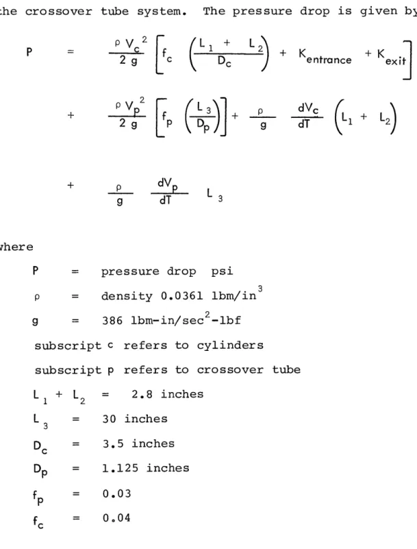
the pressure drop through the crossover tube was small.
Shop prints of the test pump unit are given in Appendix
A-3. The unit was designed around a 3.5 inch diameter by 3.5 inch tall Bellofram [Ref. 7] rolling diaphragm. The
dia-phragm had a simple flange that was perforated for six 1/4 inch bolts. All of the design dimensions relating to the diaphragm are derived directly from the Bellofram design
manual. Although long stroke diaphragms had been sought
be-fore constructing the test pump unit, they had not been found at the time the test pump unit was designed. Thus, the test unit was constructed with conventional rolling diaphragms.
The test pump embodied the concepts of straight connec-tion of the pistons to the surface and of the use of solder connections. There were no failures due to pulling the wire out of the joint. The wires did fail due to flexure. The
flexure resulted from the release of dissolved air below the pistons and from fluid inertia effects induced in trying to by-pass the problem. A few minutes operation in such a man-ner would break the cable off just above the solder joint. No cable failures occured inside the pump unit itself. Nor was any problem encountered that resulted from a reversal of the diaphragm.
inch cold rolled steel rod. This assembly worked as planned. Drilling the .082 inch diameter holes was very difficult as the drills were small, long, and flexible. Substitution of tubing for the steel rod would resolve this problem while
retaining the benefits of this construction.
The two cylinder units were connected with 30 inches
of 1-1/4 inch I.D. steel wound hydraulic hose for
conven-ience. The field unit would have been fabricated from pipe.
The diaphragm retainer was separate from the cable attachment system to avoid undue twisting of the diaphragm.
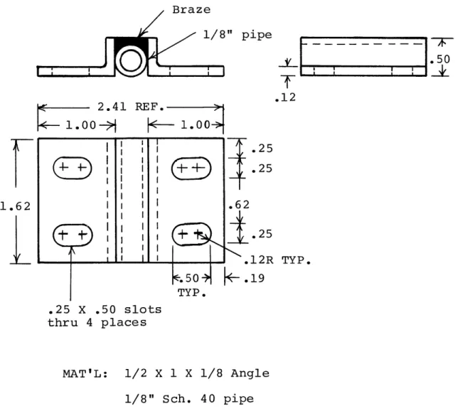
The check valves were constructed from 2 inch close pipe nipples. A plate with several orifices in it served
as a base for a rubber flapper seal. This assembly screwed
into two inch by one inch reducers on each end. The parts for this unit are shown in Figures 15 and 16.
DRIVE UNIT AND FLYWHEEL
The constructed drive unit consists of four major components:
1. bicycle
2. bicycle support
3. flywheel
The relationship of these parts is shown in Fig. 4.
The bicycle was conventional and used as is. There
were only two modifications. The first was to cut out
the rear brake mounting bracket on the back stays to clear
the flywheel. The second consisted of tightening the head tube bearing until the front forks could not turn. This
served to make the bicycle part of the triangulation of the
drive framework.
The bicycle was supported on four upright two by fours. Each upright had a bracket, shown as Fig. 20, mounted on
top with lag screws. The axles of the bicycle sat directly
in these brackets. The wheel nuts secured the bicycle to
this structure. This assembly was held together by a single
two by four acting as a backbone. This structure can be
seen in the drawings in Appendix A-2. The only problem with
this structure was splitting of the two by fours where the
lag bolts held the axle brackets down. The brackets should
be redesigned to bolt through the uprights. These brackets
should also be redesigned to permit chain adjustments. This can be accomplished with a longitudinal slot at the front axle.
The flywheel was made by wrapping one half inch strap-ping around the rear wheel. In all, 37 pounds of strapstrap-ping
was added. Four 1/4 inch bolts on 900 spacing held the strapping in place. The flywheel inertia is calculated to
be 58 lbm-ft2. The free wheel assembly was spot welded to
lock it. A 12 tooth sprocket on the rear wheel connected to the 49 tooth pedal sprocket giving a good speed ratio. This assembly was pedaled up to an estimated 80 rpm at the pedals, giving an estimated 325 rpm on the flywheel. No appreciable vibration resulted.
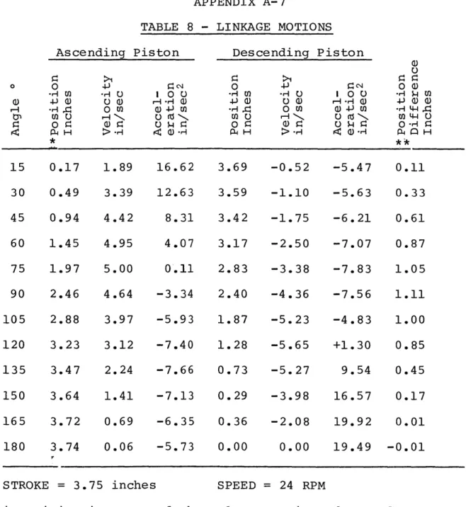
The drive linkage was fabricated of two by fours, one
by twos, and a special pedal adapter. The objective of
the linkage was to provide a piston motion that would move the ascending piston faster than the descending piston, thereby creating the driving force to return the descending piston and fill the pump cylinder with fluid. Appendix A-7 gives the position, velocity, acceleration and piston
differential motion for the linkage at 24 rpm and 3.75 inch stroke.
Two types of bearings were used in the linkage. The first is a wood bearing made of oil soaked hardwood [Fig.
17]. It fitted around the center tube of the bicycle pedal. This permitted the pedal to rotate independently of the
linkage, allowing ankling which aids in reducing operator fatigue. A wooden adapter [Fig. 21] fitted the bottom side
of the pedal tube and received 1/8 inch by 1/2 inch bent iron straps that held the assembly together. The adapter then bolted to the drive linkage. No problems were encount-ered with this system. One observation is in order, though. If the pedal center tube is only pressed into its end pieces, it may rotate in the cage instead of inside the wooden
bear-ing. This would rapidly wear out as only a small land of
metal would be taking the bearing action. If such a condi-tion were possible, the tube would have to be soldered or
welded to the pedal cage.
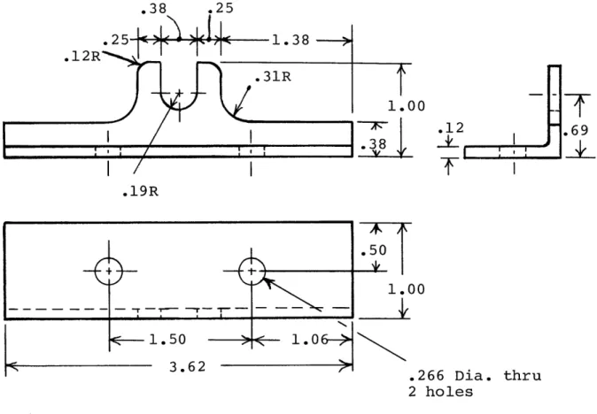
The second set of bearings consisted of 1/8 inch Schedule 40 steel pipe operating around 1/4 inch bolts. These bearings were fabricated in two forms. The first
[Fig. 17] consisted simply of short pieces of pipe pressed into holes drilled in the wood linkages. The second set consisted of a piece of pipe with flanges welded on each
side of the pipe [Fig. 18]. These were secured to the main
linkage arm by lag screws. The screws only prevented the bearings from sliding along the beam. Each of these
bear-ings was loaded compressively.
Cable adjustment was accomplished with a 12 inch long 1/4 inch threaded rod. Into this rod was soldered the music wire in precisely the same manner as the piston
connector block locked the adjustment rod into place.
Overall, the drive structure proved entirely adequate
and rugged. Except for splitting of the wood on the
sup-ports and the need for chain adjustments, the system can
be used directly in future projects.
TEST SITE AND PLATFORM
Appendix A-2 contains two views of the test site and platform. The platform was simply a four foot tall wooden
structure designed to separate the pump and drive. The upper and lower 1/2 inch plywood floors were stiffened to
take out the cable loads. The drive unit was mounted on the
upper level with the pumps being placed below. The platform was placed next to a free standing swimming pool which was
used as a source of water. A 1-1/2 inch hose of 10 feet length connected to the intake valves.
The output valves connected to a surge chamber that smoothed the output so that the unit would work against a constant pressure. The back pressure was established with an adjustable one inch popoff valve.
A small tub was used during the pumping tests as a
a line with a scribe on the side of the tub. The tub was filled to the line with water and weighed. Deducting the weight of the tub gave the volume of water held by the tub.
TEST PROGRAM
The test program sought data for three objectives:
1. Determine the pumping capacity of the pump unit.
2. Determine an approximate value of the pumping
efficiency and delineate the relative magnitude of the individual losses.
3. Determine the general acceptability of several
de-sign components including the flywheel, bicycle
mounting, drive linkage, straight line connection
of the drive cables to the pump pistons, the
piston return mechanism, the valves and the solder
connectors for the drive cables.
Six groups of experiments were conducted to answer the above objectives:
1. Pumping tests.
2. Pumping deceleration tests.
3. Linkage deceleration tests.
5. Valve pressure drop tests.
6. Vacuum leakage tests.
The first test satisfied the first objective. It,
together with tests two through five supplied efficiency data. The sixth test was done in an effort to find the cause of failure of the pump unit.
The pump was never made to operate successfully. Nevertheless, the pump did deliver more fluid at higher pressures than the pump constructed by the 2.673 group due mainly to better man-machine coupling.
In an effort to find the cause of failure, several
tests and analyses were conducted. First, the amount of
air below the pistons was determined and found to be
insufficient to cause the complete failure. Next, the
in-let system was investigated for pressure drop. This was found to be sufficiently low. In the end, a complete iter-ative analysis of the inlet and crossover flows, including inertia effects, indicated that the pump should work. Im-plicit in all these analyses was that the vapor did not change state rapidly relative to the time required for the stroke. Finally, pumping and efficiency tests were run at the best conditions possible. After this, the test pump
The pump could be cycled up to about 50 rpm without breaking the drive cables once the solder fillet had been added. However, the cable flexure was so intense that
trying to pump at these rates would have been pointless. The pump tests were done at 24 rpm which resulted in an
acceptable cable deflection. Initially, the runs were tried at 15 rpm, but this proved extremely uncomfortable to the operator. These tests, conducted at various pres-sures from 9 to 24 psi, are shown in Table 1.
The procedure for the pumping tests was as follows:
1. The popoff valve was backed off to zero pressure.
2. The rider began pedalling. A clock with a sweep
second hand was used by the rider to regulate his speed.
3. Once a steady cadence was established, the
pres-sure was increased via the popoff valve up to the
operating pressure. There were still some minor
pressure fluctuations (± 2 psi) even with the
surge chamber. Hence, the high and low gage in-dications were centered around the operating pressure.
4. As soon as a steady cadence was again determined,
receiver vessel. The time and number of pump strokes to fill the receiver vessel to a pre-calibrated depth were recorded.
This cycle was repeated for each pumping run. The 9 psi run was performed at 15 rpm and was not repeated at
24 rpm.
The next four test groups, as shown above, were con-ducted in an effort to arrive at an approximate value of the pumping efficiency. These tests also determine the relative magnitude of the losses, pointing out the main
areas for improvement.
Two of the tests, the pumping deceleration test and the linkage deceleration test, were conducted in a similar manner. The operator pedalled the pump unit up to 48 rpm. When a steady rate was determined, the operator removed his
feet from the pedals while the linkage was at its upper and lower extremes of motion. The unit, driven by the flywheel,
slowed to a stop in a number of pump strokes that was depen-dent upon the rate that energy was being expended. By
starting the deceleration at a speed that was twice that of the pumping tests, the average energy expended per stroke should be approximately the energy dissipated per stroke at the operating speed. This tacitly assumes a linear
relation-ship between energy expenditure and speed. The accuracy of this experiment, due to the flexure of the drive cables,
is such that any improvements in the efficiency analysis would probably be unjustified.
The pumping deceleration test took place as described
above. The pump was connected to pump water just as it had
been during the pumping tests. When the operator removed
his feet from the pedals, the pump output was transferred to a receiver vessel. When the pedals stopped, the flow was diverted. The flow continued for a few seconds after the pedals stopped before the popoff valve shut off the flow. This extra flow came from the discharge of the surge chamber. The volume pumped was measured and recorded. Due to the
discharging of the surge chamber, the pressure dropped from its operating level as the unit slowed down. It was gener-ally observed that the pressure dropped to roughly 1/3 of its initial value as the pump slowed. Thus, the average
pressure is estimated at 2/3 of the operating pressure. This
is certainly subject to a significant amount of error. This
value is probably no more than 20% accurate. The fluid
vol-ume is probably 5% accurate. While this flow from the
discharge of the surge chamber affected both the pressure and volume data, attempts to operate the unit without the
surge chamber resulted in totally unreadable gage variations.
A glycerine filled gage was tried to no avail. A gage
damp-ener was not tried. The results of these tests are recorded in Table 2. The operating pressure was set by adjusting the popoff valve in from zero as was done in the pumping tests. The operator adjusted his speed with a clock as in the
pump-ing tests. The speed was double checked by timing the last
20 strokes before the operator removed his feet from the
pedals. This also served as a countdown for the transfer
of the hose to the receiver vessel and for the operator to
remove his feet from the pedals.
The second series of deceleration tests were conducted to determine the losses due to the linkage. For this series of tests the diaphragms and the transfer fluid were removed
from the cylinders. The seals were unscrewed from the top
of the cylinders and slid up on the drive cables out of the
way. Thus, the pistons simply hung inside the cylinders with the wire coming out through the threaded seal hole. This constrained the linkage to follow the same motions as
in pumping. Several decelerations from 48 rpm were run. The speed was simply controlled by the operator with the clock as the load was light. The operator had no trouble maintaining a very steady cadence. An average of 20 pump
strokes was required to stop the machine. This is also
recorded in Table 2.
The seal friction is quite reasonable, averaging 7 lbf. This appears to be independent of speed over the range
en-countered in operating the pumps. The procedure for
measuring these values was to secure the seal element
pulling the wire through the seal with a scale. The wire
was attached to one of the pistons below the seal in order to keep the wire straight. The friction increased sharply if the cable were flexed in any manner. If the piston be-gan swinging, the cable could not be pulled through the seal with the scale. As the piston swung back and forth, the wire could be intermittently pulled through the seal at
high load each time the piston passed directly below it.
This fact accounts for part of the failure of the pump unit, as will be discussed in the analysis section. Steady,
smooth tests that did not swing the piston resulted in 7 pound average readings. The results did not change when the seal assembly was under water.
The valve was tested in an effort to locate the cause
of the failure of the pistons to descend. If the pressure
drop in the inlet system were too high, this could have
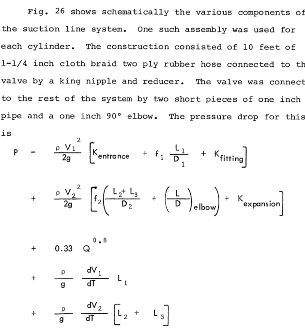
plumbing were tested. The valve is reported separately as it might be used in subsequent designs. The equation for the valve pressure drop is
P = 0.33 Q00 8
P - pressure drop - psi
Q - flow rate - gpm
The inlet plumbing test was not recorded, but was simply run to verify that the equation presented in Appendix A-5 did adequately reflect the inlet pressure drop. The inlet pres-sure drop due to friction ranged from 2 to 6 psi over the flow range up to 20 gpm. The flow rate, however, was only visually estimated by the distance it traveled after it left the plumbing.
The final test was a measure of the vacuum holding
ability of the pump units. Each piston was raised up to
within approximately 1/2 inch of its cylinder top. This
created the maximum vacuum possible with the system. Over a period of four days, this condition was maintained. The cable tension was tested by "plucking" the cables twice
pitch occurred indicating the unit did not leak air at any
significant rate.
ANALYSIS
Following the test program and dismantling of the pump and drive units, it was discovered that the pump should not have worked at all with the pistons raised. The reason for this is the extremely rapid rate at which a fluid and vapor system will seek equilibrium. The effect of the rate of equilibriation being so high is that very little pressure difference is generated between the vapor and fluid in eith-er condensation or vaporization. As a result, no signifi-cant pressure was developed to accelerate and transfer the fluid below the pistons. Appendix A-6 shows the derivation of the pressure drop in evaporation or condensation. At the point that the bottom of Piston A strikes the surface of the
fluid, it begins accelerating the fluid. When the annulus between the cylinder and piston below the diaphragm fills
with fluid the piston can readily transfer the fluid to the
opposite side. However, in accelerating the fluid, the piston momentarily lags the linkage, causing the initial
any deviation from straight motion dramatically increased the seal friction. For most of the remainder of the stroke, the seal friction retards the motion of the piston limiting transfer of the linkage fluid and limiting the intake of fluid into the cylinder. This entire sequence of events is adequately supported by the fact that the cable flexure
occurred also with the plumbing disconnected. In this form, no loads were placed on the working side of the diaphragm. Appendix A-5 presents calculations showing the inlet and transfer losses, demonstrating the low value of these pres-sure drops at the operating speed. While the inlet losses are rather high, they are not significantly high enough to cause the failure of the piston motion. The entire inlet plumbing was flow tested confirming the overall friction drop but no adequately simple system was devised to test the acceleration component. However, in light of the agreement on friction losses, it is reasonable to assume the inertia
load is correct.
The entire problem with the test pump could have been solved by using deaerated water. However, it did not seem feasible, due to the construction of the pump unit, to get deaerated water into the pump without entraining air both in
bypassed for the loading with regular water since the pumps
could be filled and sealed totally under water in the
swim-ming pool.
If a greater spacing between the drive and the pump had existed, thereby limiting the initial flexure upon accelera-tion of the fluid mass, it is entirely possible that the seal
friction would not have risen so sharply and the pump could have been made to function. Nevertheless, this mechanism is clearly undesirable even with longer cables as the shock on
the cables would accelerate their breakage.
The second series of tests were aimed at determining an approximate value for the overall efficiency of the pumping unit and to isolate the major losses. The major losses in the test unit occurred in the linkage and seals.
By operating the pump unit, and later the linkage, at
roughly twice the speed of the pumping tests, it is possible to obtain an approximate value of the energy expended per
stroke at the speed of the pumping tests. This is done by
dividing the total energy available less that expended to
pumping fluid by the number of strokes required to stop the
machine. This procedure tacitly assumes a linear
relation-ship between losses and speed, while obviously, fluid losses vary as the square of the speed. However, in light of the problems encountered in pumping; this is sufficiently
accur-ate. Table 2 shows the series of efficiency runs. Here, the pump was operated between 45 and 48 rpm and then permit-ted to stop, using the energy of the flywheel. This
proced-ure has been described in the test section. The number of
strokes to stoppage, the volume of fluid pumped, and the operating pressure under power were recorded. From the speed, the energy of the flywheel can be determined. The
inertia of the flywheel is 58 lbm-ft 2. The energy for each
run is shown in Table 2.
As was discussed in the test section, the pressure drop-ped during the slowdown of the pumping unit. Thus, part of
the flow obtained during the stoppage came from the surge chamber. The final pressure in the surge chamber is estimat-ed to be 1/3 of the initial pressure. Table 3 presents the volume differences for an isothermal expansion of the gas in
the surge chamber from the initial pressure to 1/3 of that
pressure. These volumes are deducted from the delivered vol-ume in Table 2 resulting in the corrected volvol-umes shown. The work delivered is the product of the corrected volume and the
estimated average pressure. The remaining flywheel energy
must be expended in various losses. The average loss per
pump stroke is presented in the final column. The overall
average loss is 52 ft-lbf/stroke.
stoppage test is 17 ft-lbf/stroke based on 48 rpm initial speed and 20 strokes to stoppage.
The nominal seal friction accounts for 4 ft-lbf/stroke when no increase in drag occurs due to bending. Under the
conditions encountered with the test pump, the seal friction clearly accounted for the major part of the remaining losses.
By the analysis of the transfer fluid presented in Appendix
A-5 the transfer fluid accounts for approximately .5 ft-lbf/
stroke. The intake losses amount to approximately 4 ft-lbf/
stroke.
The pumping data is presented in Table 1. The first
three columns -- pressure, number of strokes and time
--are the source data. The remaining information is derived. The % filling column is based on the theoretical stroke
vol-ume of 39.2 in3/stroke which requires 67.1 strokes to fill
the 11.4 gallon receiver vessel. The net work is the
deliv-ered volume times the operating pressure. The energy per
stroke is the key value from this table related to
effic-iency. The fact that the deceleration tests result in lower
delivered work per stroke should cause an over estimate of the losses occurring at the operating speed. Table 4
pre-sents the efficiencies resulting from this analysis for
for this table. Significantly higher efficiencies could result for this pump in the event that the initial flexure did not increase the seal friction. But the overall process is clearly undesirable.
A final note on the operation of vapor return pumps is
the impact of dissolved air on the system. Dissolved air
tends to reduce the internal pressure of the transfer system while simultaneously generating part of the gas compression
and expansion pressure difference initially intended to transfer the fluid between cylinders. A drawback to the presence of air is that the pistons must always be operated such that there is sufficient volume within the cylinder system to keep the air at sufficiently low pressures. The
only practical way to do this is to use part of the
dia-phragm stroke as a preload cycle. This also is undesirable. Based upon this analysis, then the following
recommen-dations and observations result.
1. The vapor pressure vacuum system can return the
piston under the proper design conditions.
Such conditions would seek to reduce or eliminate
the forces imposed upon the piston when it encoun-ters the fluid.
capacity for dissolved air. Correspondingly, the pump should be designed so that all the air
below the piston can be purged.
3. The inlet losses should be minimized. In the
test pump fairly high losses were encountered due to the need to draw water from the swimming
pool to pump through roughly 12 feet of hose and
pipe.
4. The valves should be equipped with better flappers
to reduce or eliminate back flow. Alternatively,
another valve could be designed or procured.
5. The seals are entirely adequate provided no cable
flexure occurs. This requires a continuous
ten-sile load on the cable. The seal assemblies
should be fabricated from small bore tubing to eliminate the drilling operation.
6. The flywheel mass can be reduced to at least half
of its 58 lbm-ft2 value without adversely
affect-ing operation.
7. The solder joint system for the drive cables
work-ed extremely well and is recommendwork-ed as it rwork-educes stresses in the cable to a minimum.
reduc-tion in linkage drag can be obtained by
separat-ing the members from each other with washers. The linkage members slid against each other dur-ing operation. Spacdur-ing them apart should
eliminate the friction that results.
9. The bearing assembly at the pedal, to permit
ankling, is considered very important in that it reduces operator strain, just as it does in
regular bicycling. Constraining the pedal to
follow the motion of some part of the linkage,
as would occur by simply bolting the pedal to a linkage element, particularly should be avoided.
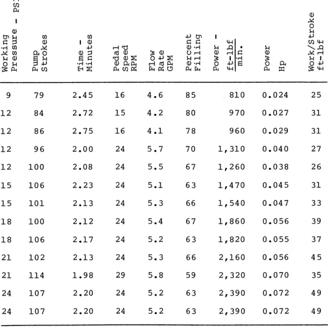
TABLE 1 PUMPING TESTS ,Qo* I H Q) 0 -P Q.4 0 -P-9 79 2.45 12 84 2.72 12 86 2.75 12 96 2.00 12 100 15 106 15 101 18 100 18 106 21 102 21 114 24 107 24 107 2.08 2.23 2.13 2.12 2.17 2.13 1.98 2.20 2.20 16 4.6 15 4.2 16 4.1 24 5.7 24 5.5 24 5.1 24 5.3 24 5.4 24 5.2 24 5.3 29 5.8 24 5.2 24 5.2 810 0.024 970 0.027 960 0.029 70 1,310 0.040 67 1,260 0.038 63 1,470 0.045 66 1,540 0.047 67 1,860 0.056 63 1,820 0.055 66 2,160 0.056 59 2,320 0.070 63 2,390 0.072 63 2,390 0.072
67.1 strokes required to fill 11.4 gallon receiver
vessel at 100% volume efficiency. Theoretical pump displace-3 ment = 39.2 in -Y, 040 r-4 iO Hrd rda) z P4U) Z~ H M Q) 25 31 31 27 26 31 33 39 37 45 35 49 49
PUMPING DECELERATION TESTS W I o4-) rd a) a) 4-W U) s . rJa)th 0 -> U S0:r-I:1 U) > () 9 12.5 15 12.5 18 13.3 21 13.9 24 13.6 48 6.2 48 6.0 45 5.0 43 4.2 44 4.0 380 380 330 300 320 6 150 10 142 12 132 14 115 16 102 34 116 58 15 9 40 102 85 22 14 42 90 90 27 18 43 72 84 28 20 43 59 79 25 20
LINKAGE DECELERATION TESTS
The linkage averaged 20 strokes to stop from 48 rpm.
Average loss per stroke is 19 ft-lbf/stroke.
WU) H 0-Po CD ro c4 P m :: ro I 0 0 a) .! 4--IH 0Oa -Pi car P4W $-i 0 0 4--P.I a) I2 a) N a) LH M~ > ,q 4 H-4 Wa) 4 -4
TABLE 3
SURGE CHAMBER VOLUME CHANGES Initial Pressure PSIG Initial Volume cu. in. 100 15 18 Final Pressure PSIG Final Volume cu. in. 134 127 120 114 109 104 Differential Volume cu. in. 34 38 40 42 43 43 ISOTHERMAL EXPANSION V0 PV = CONST = 14.7 psia = 161 cu. in.
TABLE 4
ESTIMATED PUMPING EFFICIENCIES
Working Pressure PSIG Total Energy per Stroke ft-lbf Pumping Energy per Stroke ft-lbf Losses per Stroke ft-lbf Efficiency Percent 15 81 32 49 40 18 87 38 49 44 21 92 40 52 43 24 109 49 60 45
NOTE: 9 psi run deleted due to speed of 16 rpm. 12 psi run deleted due to error in recording
SECTION III
PROPOSED UNITS
PROPOSED PUMP REDESIGN
The cause of failure of the test pump stemmed from two original problems. First, dissolved air came out of solu-tion eliminating the vacuum that would have returned the pistons. Second, in an effort to hold vacuum the pistons were raised by shortening the stroke. In this case, when
the piston struck the surface of the water, the piston
slowed as it accelerated the transfer fluid. This led to
cable flexure and increased seal drag.
The original concept of returning the pistons to the surface of the fluid so that no permanent vacuum exists is valid. What is required is elimination of dissolved air and significant fluid forces acting on the piston. The air can be eliminated by two methods. One, deaerate the fluid below
the piston. Two, use a fluid that has very low air absorp-tion. Boiled water is a simple solution provided the water can be transferred to the pump without reabsorption. Oils hold less air than water but the author has no data on how
much they do hold.
Provided such a fluid is supplied under the pistons, the pistons will return readily. Fig. 1 shows a proposed design for a single acting pump. The piston is shown at
midstroke and the fluid below the piston is illustrated.
The piston is hollow which reduces fluid displacement to a minimum. The only fluid force on the piston is simple fluid resistance due to the motion of the piston walls through the fluid. For sufficiently inviscid fluids, in-cluding oils, below the piston, the'inlet losses should exceed the vacuum before the piston drag becomes too great.
At the end of a pumping session the piston is simply left
at the bottom of the cylinder with no vacuum below the
piston. Guide vanes keep the piston from cocking in the
cylinder.
The proposed pump uses one of the Diaphragm Industries'
long stroke diaphragms. This reduces the pump diameter to
as small as practical or necessary. This pump could be used from 25 feet to 100 feet. The stroke would vary from
13 inches to 3.25 inches respectively for a fluid output of
0.07 horsepower. At 70% efficiency this would require 0.10
horsepower input. The pressure rating of 50 psi restricts
The intake valve is built into the top of the cylinder.
It consists of a flexible rubber sleeve that covers ports drilled around the periphery of the cylinder. Spring load-ed fingers as part of the mounting bracket at the top of
the sleeve should help seat the valve. The discharge valve
is screwed into the top of the cylinder. The seal is con-tained in the center of the discharge valve. A reducer
connects the pump to the discharge line. The drive cable is inside the discharge pipe where it is protected. The flange for the diaphragm is not load bearing. The solder connector
is pinned to the piston rather than threaded into the piston.
The reason for this and the concern for the flange bolts
arises from a statement in the Battelle report [Ref. 3] indi-cating that very poor thread quality in bolts can be expect ed. Consequently, as many as possible threaded components loaded in tension should be eliminated. To keep the flange bolt loads down, any ballast weight would be applied around
the drop pipe. This also reduces the depth of water that the pump needs.
Appendix A-4 contains a letter from Diaphragm Industries stating the feasibility of the diaphragm and its estimated cost. Estimating twenty eight dollars for the diaphragm and
fifteen dollars for the bicycle, this assembly could easily
Fig. 2 shows schematically the scheme to adapt the bicycle drive to a single acting pump. If the pump link-age is connected to the left bicycle pedal, then the left
foot must press with one half the effective pump load dur-ing the power stroke. And the right foot must press with one half the effective pump load during the suction stroke.
Thus, the rider sees a continuous load. Flywheel inertia is still required, but only about 20 pounds of weight is required on the rim of the bicycle wheel.
This design should provide an extremely cost effective man powered water pump for medium lifts. Conversations with Diaphragm Industries have indicated that it could be possi-ble to extend the capacity of the diaphragms to 100 psi. This would extend the utility of the pump unit.
PROPOSED WELL DRILLING SYSTEM
The Battelle report [Ref. 2 ] has indicated that the AID and other groups are or have in the past drilled water wells for hand pumps. It also reported a cost of $0.26 per inch diameter per foot of well. The proposed pump
re-quires a 4-1/2 inch hole. For 100 feet this hole costs $117. This cost is quite old and could be low by as much
as a factor of 2. This cost alone significantly exceeds
the cost of the pump. As such, this fact will seriously
affect the dissemination and use of these pumps. A reduc-tion in the cost of drilled wells would greatly enhance the utility of these systems.
One possible and recommended system is to develop a bicycle powered well drilling system. Such a system would necessarily be simple. This would place the development of water sources in the hands of the people that would use it. Fig. 3 shows schematically how such a system might be configured. The principle of operation is that of a cable
tool drilling unit. The tool is suspended from the end of
a drilling line. The line is rapidly raised and lowered. Once the proper operating conditions are established, the tool, which weighs 200 to 400 pounds, is springing on the
end of the drilling line. This springing causes a very
sharp bounce of the tool on the bottom of the hole. However, already having the cable tensioned quickly pulls the tool
from the work face preventing sticking. The cutting end of the tool is fashioned in a manner to force the tool to
ro-tate. Rotation of the tool causes a straight round hole to
be drilled. The oscillations of the bit keep the cuttings
upon conditions, six inches to a few feet can be drilled before the drilling tool must be pulled and the cuttings removed.
The bicycle is used to drive a crank and flywheel.
The crank needs to rotate between 20 and 40 rpm in order to set up the proper bouncing reaction of the drilling tool. The walking beam should have a number of stroke adjustments as the frequency is partially dependent upon stroke. Fly-wheel energy storage of about 5,000 ft-lbf is required. This is a four foot diameter by three inch thick flywheel rotating at 120 rpm. This could be connected to the crank
by bicycle chains and sprockets.
The feed spool should also be driven by a bicycle.
However, it is only used intermittently during removal of the tool or bailer. During drilling, line from the feed spool is gradually let out as the drilling progresses.
This drilling system could cut from a few feet per day up to perhaps 15 feet per day in soft formations. Only two people would be required to drill a well.
Such a system could probably be built for $500
includ-ing a trailer in which to haul the equipment (especially
the flywheel). Implementation and introduction of a system
the hands of the people of underdeveloped countries. Their own initiative and ingenuity would take care of the rest.
CONCLUSIONS
The work described in this paper has led to a pump
de-sign that resolves all the problems with piston return that
were encountered. Use of long stroke diaphragms, redesign and integration of the valving and conversion to a single acting pump has produced a very efficient cost effective pump design. It is recommended that this design be built and tested. Implementation of pumps along these lines
could resolve much of the water problem in underdeveloped regions.
These pumps are only part of the solution of the prob-lem, however. Development of the proposed drilling system would have substantial impact on the overall problem of
water development in underdeveloped regions. In particular,
this device would place the initiative and capability for
the water development with the people who would use the
water. Such a situation would increase the acceptability
of the pumps and systems. It would also hasten development
as the people realized the capacity to create their own water supply.
BIBLIOGRAPHY
1. Asbell, 0. David, Bricker, James A., Guaraldi, Paul E., and Stellinger, Thomas, Man Powered Pump, 1969. 2.673 Project Report, Professor D. G. Wilson, advisor.
2. Frink, D. W., Fannon, R. D., Jr., The Development of a Water Pump for Underdeveloped Countries to Agency for International Development, 1967. Page A-2. Battelle Memorial Institute Research Report.
3. Frink, D. W. - ibid, p. 35.
4. Idel'chik, I. E. Handbook of Hydraulic Resistance, 1960. Israel Program for Scientific Translations,
Ltd. 1966 IPST cat. No. 1505. Published in the United States by the Atomic Energy Commission. AEC-tr-6630, p. 280.
5. Idel'chik, I. E. - ibid, p. 266.
6. Schrage, Robert W., A Theoretical Study of Interphase Mass Transfer, 1953, Columbia University, New York. Chapters 1 and 2.
7. Bellofram Corporation, Design Manual, 1962. Burling-ton, Massachusetts.
APPENDICES
APPENDIX A-i