HAL Id: hal-00007573
https://hal.archives-ouvertes.fr/hal-00007573
Submitted on 27 Jul 2005
HAL is a multi-disciplinary open access
archive for the deposit and dissemination of
sci-entific research documents, whether they are
pub-lished or not. The documents may come from
teaching and research institutions in France or
abroad, or from public or private research centers.
L’archive ouverte pluridisciplinaire HAL, est
destinée au dépôt et à la diffusion de documents
scientifiques de niveau recherche, publiés ou non,
émanant des établissements d’enseignement et de
recherche français ou étrangers, des laboratoires
publics ou privés.
interferometry
Pierre Kern, Jean-Philippe Berger, Pierre Haguenauer, Fabien Malbet, Karine
Perraut
To cite this version:
Pierre Kern, Jean-Philippe Berger, Pierre Haguenauer, Fabien Malbet, Karine Perraut. Planar
Inte-grated Optics and astronomical interferometry. Comptes Rendus Physique, Centre Mersenne, 2001,
2, numéro 1, pp.111-124. �hal-00007573�
ccsd-00007573, version 1 - 27 Jul 2005
interferometry
Optique Int´egr´ee planaire pour l’interf´erom´etrie appliqu´ee `a l’astronomie
Pierre Kern1
, Jean Philippe Berger2
, Pierre Haguenauer23
, Fabien Malbet1
, and Karine Perraut1
1
Laboratoire d’Astrophysique de l’Observatoire de Grenoble BP 53, 38041 Grenoble Cedex 9, France
2
Laboratoire d’Electromagn´etisme Microondes et Opto´electronique BP 257, 38016 Grenoble Cedex 1, France
3
CSO mesure,70 rue des Martyrs, 38000 Grenoble, France
Abstract. Integrated optics (IO) is an optical technology that allows to repro-duce optical circuits on a planar substrate. Since 1996, we have investigated the potentiality of IO in the framework of astronomical single mode interferometry. We review in this paper the principles of IO, the requirements for interferometry and the corresponding solutions offered by IO, the results of component characterization and the possible fields of application.
Keywords:Interferometry, Optical aperture synthesis, Integrated Optics, Pla-nar Optics, Single mode optics.
Abstract. L’optique int´egr´ee est une technologie qui permet de reproduire des cir-cuits optiques sur un substrat planaire. Depuis 1996, nous menons des recherches sur les potentialit´es de l’optique int´egr´ee dans le contexte de l’interf´erom´etrie monomode en astronomie. Dans cet article, nous passons en revue les principes de l’optique int´egr´ee, les sp´ecifications propres `a l’interf´erom´etrie et les solutions correspon-dantes offertes par cette technologie, les r´esultats de caract´erisations de composants ainsi que les domaines d’application.
Mots cl´es : interf´erom´etrie, synth`ese d’ouverture optique, optique int´egr´ee, optique planaire, optique monomode.
1
Introduction
The use of guided optics for stellar interferometry was introduced to reduce constraints while combining coherent beams coming from several telescopes of an interferometer. Claude Froehly proposed in 1981 [1] to use single mode fibers to solve the problems linked to the beam transportation and high num-ber of degrees of freedom of such an instrument. Laboratory developments [2] [3] and on the sky experiments [4] have shown the important improvements introduced by guided optics. More than experimental setup simplification,
Fig. 1.Principle of mode propagation within a waveguide.
single mode guided optics introduces modal filtering which allows translation of the phase disturbance for the incoming wavefronts into calibrable intensity fluctuations.
The analysis of existing fiber-based experiments led us to propose pla-nar integrated optics (hereafter IO) as a solution for some of the remain-ing difficulties linked to fiber optics properties or to the general instrument setup [6],[7]. In this paper, we present a review of the work done since 1996 by the team composed of partners from research laboratories (Laboratoire d’Astrophysique de l’Observatoire de Grenoble - LAOG, CEA/LETI and Laboratoire d’Electromagn´etisme Microondes et Opto´electronique - LEMO) and from industrial laboratories (GeeO, CSO). Section 2 presents the princi-ple of planar IO and an introduction to the related technology. This section presents also typical available IO functions. Section 3 summarizes the re-quirements for an interferometric instrument and the solutions offered by IO. Section 4 presents the results obtained during that period and shows how IO can be a convenient solution for the instrumentation for interferometry. The last section gives some perspectives of our developments.
2
Integrated Optics technology
2.1 Planar optics principle
Optical communications using single mode fiber optics for long distance con-nection impose periodic signal amplification. Triggered by telecommunica-tions industry requirements, major efforts have been done to manufacture compact single chip repeaters directly connected to fibers avoiding multiple signal conversion [8].This has lead to develop techniques able to integrate complex optical circuits, as for integrated electronics, on small chips. The main technological breakthrough resided in the ability of integrating single-mode waveguides in a given substrate.
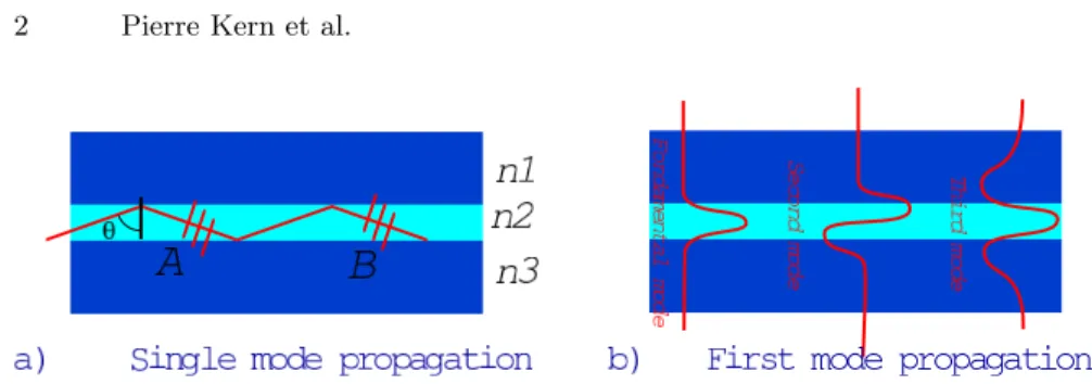
In a planar waveguide (Fig. 1a) optical guidance is guaranteed by the three step-index infinite planar layers (n2> n1and n3) [9]. The core layer thickness
of index n3 ranges between λ/2 and 10λ depending on index difference ∆n.
description, shows that the modal beam propagation applies in waveguide structure [9]. The main part of the carried energy lies in the waveguide core, but evanescent field propagates in lateral layers and contribute to the mode propagation. A guiding structure with a given thickness and layers refractive index is characterized by a cut-off wavelength λc, separating the single mode
propagation (λ > λc) where only the fundamental mode propagates and the
multimode propagation condition (λ ≤ λc, Fig. 1b).
Only the single mode regime is considered in our developments. However multimode guided structures have been tested [10] for stellar interferometry.
2.2 Waveguide manufacturing
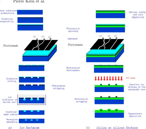
The guided area is obtained by ion exchange technique [11]. The Na+ ions of the glass substrate are exchanged by diffusion process with ions K+, Ti+, Ag+ of molten salts and result in an increase of the refractive index, produc-ing the three-layer structure (air / ions / glass) capable to confine vertically the light. The implementation of the optical circuit is obtained by standard photomasking techniques (see Fig. 2 left) to ensure the horizontal confine-ment of the light. While ion exchange occurs at the surface of the glass, an additional step of the process can embed the guide, either by applying an electric field to force the ions to migrate inside the structure or by depositing a silica layer. The waveguide core is the ion exchange area and the cladding the glass substrate or the glass substrate and air. Depending on the type of ions, ∆n can range between 0.009 and 0.1. This technology produced in Grenoble by LEMO and GeeO/Teem Photonics is commonly used for various components used in telecom and metrology applications.
The waveguide structure can also be obtained by the etching of silica layers [12] of various refracting indices (phosphorus-doped silica or silicon-nitride). As for other techniques photomasking is required to implement the optical circuit (see Fig. 2 right). The manufacturing process allows to choose either a high ∆n (∆n ≥ 0.5) to implement the whole circuit on a very small chip with small radii curves, or very low (0.003 ≤ ∆n ≤ 0.015) for a high coupling efficiency with optical fibers. This technology is used at CEA / LETI to produce components for various industrial applications (telecommunication, gyroscopes, Fabry-P´erot cavities or interferometric displacement sensors).
Single mode waveguide structure are also produced by UV light inscription onto polymers. The transmission of the obtained components are still too small for our applications. A technology based on LiN bO3 cristal doping
by metals allows to produce single-mode waveguides with interesting electro-optical properties but this has not been tested yet for our specific applications.
Fig. 2.Ion exchange (LEMO) and etching (LETI/CEA) techniques
2.3 Planar optics functions
Several functions working at standard telecom wavelengths (0.8 µm, 1.3 µm and 1.5 µm) are available with the different technologies. Figure 3 displays an example of IO chip used in an interferometric displacement sensor [13]. It nicely illustrates IO capability because it contains nearly all basic functions. The reference channel of the interferometer head and the measurement chan-nel are provided by splitting the He-Ne light by a direct Y-junction. The light of the measurement channel, retroreflected is injected again in the waveguide and directed to the interferometer head thanks to a directional coupler. The interferometer head is a large planar guide fed by two tapers. Interference between the two beams produces fringes which are sampled by four straight guides, providing measurements with λ/4 phase difference at the same time. The most common functions are listed below:
• Direct Y-junctions for achromatic 50/50 power splitting.
• Reverse Y-junctions for elementary beam combination as bulk optics beam splitters with only one output. The flux to the second interfero-metric state in phase opposition is radiated into the substrate.
• Directional couplers allow the transfer of the propagated modes between neighbour guides. The power ratio division in each output beam is linked
Fig. 3. Planar Optics displacement sensor developed by LEMO [13] and corre-sponding function list.
to the guide separation, the interaction length and the wavelength. Sym-metrical couplers ensure a chromatic separation of the signal. Achromatic separation requires an asymmetrical design.
• X-crossings with large angles (≥ 10◦ ) for guide crossing with
negligi-ble cross-talk effects. Smaller angles favor power exchange between the guides;
• Straight waveguides.
• Curved waveguides give flexibility to reduce the component size. Possible curvature radii depend on the core and substrate index difference. • Tapers or adiabatic transitions, thanks to smooth transition of the guide
section, adapt propagation from a single mode straight waveguide to a larger waveguide. Consequently light propagates and remain in the fun-damental mode of the multimode output waveguide. These components reduce the divergence of the output beam.
3
Instrumental requirements in stellar interferometry
3.1 Functional requirements
The wavefront distortion, due to atmospheric transmission or to instrumental aberrations, induces fringe visibility losses. The main errors can be corrected by an adaptive optics system or by an appropriate optical design adjusting the entrance pupil diameter to the local value of atmospheric coherence area diameter for the considered wavelength. The remaining phase errors on the incoming wavefront can be removed using a spatial or modal filtering [5]. The high spatial frequencies introduced by the wavefront distortion are rejected by a field stop in the Fourier plane. The diffraction limited image of an unresolved object leads to a beam ´etendue of SΩ = λ2
single mode propagation with no longer pupil and focal plane position. This fundamental mode is properly directed by a single-mode waveguide (fiber optics or planar waveguide) when it meet the λ2
beam ´etendue condition. If higher modes enter the waveguides they are rejected out of the core according to propagation laws. This modal filtering is wavelength dependent. Current simulations are in progress [21] to determine the appropriate dimensions of the guide to operate an efficient filtering: waveguide diameter, required guide length, operating wavelength range.
When a modal filtering is applied, phase distortions are translated into intensity variations in the waveguide. To calibrate the contrast of the fringe pattern, a photometric correction can be applied on the recorded interfero-metric signal taking into account the flux variations for each incoming beam. The variation of the telescope fluxes are monitored together with the inter-ferometric signal. Associated to the modal filtering, photometric calibration allows significant improvements of the fringe visibility estimation. This prin-ciple has been applied successfully with accuracy down to 0.3% with the FLUOR instrument [4].
Observation over atmospheric spectral bands are required in many appli-cations. Wavelength dependent parameters may affect the extraction of the interferometric signal. The bias introduced by differential chromatic disper-sion between interferometer arms due to optical components must be com-pensated or calibrated.
Instrumental differential rotations and phase shifts between the polariza-tion direcpolariza-tions can affect the fringe visibility. Symmetric optical design allows to reduce polarization effects but high contrasts require the compensation of the differential effects on polarizations [22] by Babinet compensators sug-gested by Reynaud [23] or Lef`evre fiber loops.
The optical path equalization is necessary from the interference location to the stellar object with a sub-micrometer accuracy. Delay lines operates this optical function. Fiber optics solution have been proposed and tested in laboratory [24], [25]. Differential fiber dispersion remains the limiting factor of the proposed concept. ESO prototype fringe sensor unit [26] uses a fiber optics delay line.
Finally, very high OPD stability is mandatory, especially for phase closure. Variations of the OPD leads to phase relationship loss and reduce the image reconstruction capability. The opto-mechanical stability of the instrument strongly affects the fringe complex visibility.
3.2 System requirements
The beam combiner ensures visibility and phase coding of the interference pattern. Telescope combiner for more than 3 telescopes are required to obtain synthesized images. The image reconstruction implies very accurate phase difference control between the interferometer arms. The beam combination
can be done either using single mode or multimode optical field. In each case, the combination is performed using coaxial or multi-axial beams.
The spectral dispersion of the fringes is used for either astrophysical pa-rameter extraction, or for fringe detection. Stellar interferometry is gener-ally performed within the standard atmospheric spectral windows of ground-based observation. The spectral analysis is achieved either by using optical path difference modulation (double Fourier Transform mode) [14] in coaxial mode or with dispersive components. In the latter case, the fringe light is focused on the spectrograph slit using a cylindrical optics [15] to concentrate the flux along the slit.
A fringe tracker allow longer acquisition times and increase the instru-ment sensitivity. Time dependent behaviors affect the central white fringe position: sidereal motion, instrument flexures and fine telescope pointing de-cay on smaller scale. Finally atmospheric turbulence affects ground based ob-servations inducing atmospheric piston at the interferometer baseline scale. The fringe tracker ensures the fringe stability thanks to a suitable delay-line controlled with a proper sampling of the OPD fluctuations at a frequency compatible with the considered time scale. It avoids visibility losses due to fringe blurring. The fringe sensor is part of the fringe tracker, it is aimed to measure the central fringe location of the interference pattern with suitable accuracy. Various principles have been proposed [16], [17], [18]. Multi-axial mode allows a complete sampling in a single acquisition, while coaxial mode requires an OPD active modulation.
Astrometrical mode requires milli-arcsecond positioning accuracy on si-multaneous observations on two distant stars. Such measurements require an appropriate metrology control of the optical path length for the two stars, from the telescope entrance to the fringe detection device.
More recently for search of faint objects around bright stars, instruments using interferometry have been proposed [19]. The on-axis star light is extin-guished thanks to a π phase delay on one of the interferometer arms before combination, providing a nulling interferometer. Fringe separation is adjusted to place the central fringe of the off-axis searched object interference pattern on the black fringe position. Interferometer pupil arrangement is optimized to obtain enhanced central star light rejection.
3.3 IO: a promising solution
Intrinsic properties of planar IO solve a large part of the functional require-ments described above of an instrument dedicated to interferometry mostly due to its ability to propagate only the fundamental mode of the electromag-netic field:
• Single mode propagation within a half octave without significant losses [29].
• Broad band transmission if the used functions are compatible with an achromatic transmission (available for individual J, H and K atmospheric bands) [29], [30].
• Intrinsic polarization maintaining behavior for most of the cases [31]. • High optical stability on a single chip [31].
• Accurate optical path equality (leq2µm) if suitable care is applied in the design and in the component manufacturing [32].
• Reduced differential effects between interferometric paths, since they are all manufactured during the same process on the same substrate [32]. • Photometric calibration easily implemented using existing basic functions
(direct Y junction, directional coupler)
• Measurements performed at LEMO shows that temperature constraints applied on a component only introduces λ/90000 / mm/◦C) phase shift
compatible with phase closure requirements [31].
Moreover, existing IO systems are also able to provide part of the required subsystem for interferometry in astronomy:
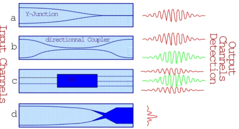
• Beam combination can be achieved either in coaxial mode by reverse Y-junction, directional couplers, Multi Mode Interferometer [33] (MMI) and/or by tapers in multi-axial mode (see Fig. 4).
• The output of a taper interferometer produces an illumination along a single direction suitable for spectrograph entrance slit.
• Using beam combiner for fringe sensing, many solutions may be applied: – A coaxial combiner with 2 outputs in phase opposition, or 4 outputs with a π/4 phase difference provides the proper fringe sampling [40]. More phase samples can be provided by small OPD modulation. – A suitable sampling of the dispersed output of a taper interferometer
can also be used on an array detector for a fringe sensing using the Koechlin arrangement [17].
• Several interferometric displacement sensors have been proposed and even offer for sell using planar optics. The existing concepts are directly appli-cable to metrology for interferometry [13].
• Nulling interferometry requires a π phase shift. Interferometer including such functionality has been tested for industrial use with laser.
4
Main results
A strong collaboration between LAOG and IO specialists (LEMO, LETI, GeeO, Teem Photonics) have given us the oportunity to propose a complete development program. Starting from available off-the-shelves components, we demonstrated the ability of the concept to meet the requirements of interfer-ometry [27], [28]. From the first analysis, we have developed adapted compo-nents for astronomy, with suitable designs. Systematic tests were performed
Fig. 4. Available beam combiners. For the reverse Y-junction (a) part of the sig-nal, in phase opposition, is radiated inside the substrate. Directional coupler (b) provides two outputs in phase opposition. MMI design (c) corrects this functional loss, providing three outputs. Each external guide collects 1/4 of the interferomet-ric signal and provide modulated light in phase opposition with the central guide (which contains 1/2 of the interferometric signal). The taper interferometer (d) ensures spatial encoding of the fringes whose sampling depend on the two taper characteristics (angles, dimensions).
on first set of components realized with ion exchanged and etching technique [29], [30]. We are starting now developments leading to new functions or new waveguide technology. We will then be able to propose first concepts of fully integrated instrument.
Theoretical investigations are also in progress to optimize the combiner parameters [21] and analyze the influence of guided beam on interferometric scientific data.
4.1 Instrumental testbeds
Systematic measurements have been performed on our components to check their ability to fulfill interferometry requirements:
• Photometric measurements to characterize all our components transmis-sion over the whole spectral band and the transmistransmis-sion of each function implemented on the corresponding substrate.
• A waveguide mode characterization and cut-off wavelength determination has been performed thanks to an analysis of the intensity spread out in the image of the exiting mode and spectral analysis of the output signal for the whole bandwidth [29].
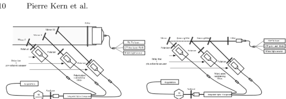
• A Mach Zehnder bench is used for interferometric qualification (Fig. 5a). A collimator illuminated by a fiber optics produces a plane wave. It is illu-minated either with a He-Ne laser (alignment needs), a laser diode (fringe localization) or a white light source (broad band characterization). The
Fig. 5. Interferometric characterization benches: a) Mach Zehnder bench (ampli-tude separation ) for interferometric characterization of the components (right) b) Interferometer simulator (wavefront separation) for image reconstruction (left).
collimated light is splitted by one or several bulk optics beam splitters. The provided channels are imaged on fiber connected to the inputs of the component.
• A stellar interferometer simulator (Fig. 5b) for phase closure characteriza-tion. In this bench the incoming wavefront is sampled by several apertures with baseline / pupil ratio compatible with real stellar interferometer con-ditions. It provides unresolved images of a complex object for individual aperture, which can be resolved by the simulated baselines.
• In any case the polarization behavior has to be carefully characterized. For all of these test benches, polarizers associated with polarization main-taining fibers ensure the polarization control of the light.
4.2 Results with off-the-shelves components
For a first validation step, part of an existing component was used in order to combine two beams in coaxial mode. This component contains 2 direct Y-junctions providing a 50/50 beam splitting for photometric calibration for both inputs and one reverse Y-junction to provide the interferometric combination. This component obtained by ion exchange technique (Ag +) was fully characterized [28], [29] (see Figure 6).
For these tests special care were given to the components / fiber optics connection. These components were produced and connected by GeeO. It provides 92% fringe contrast on the whole H atmospheric band. The opti-mized contrasts was obtained thanks to excellent polarization behavior, with a contrast stability over several hours as low as 2%. The photometric trans-mission is 43%. The main loss of this component is due to the Y-junction. Using optimized component, this transmission can reach 60% with Y-junction and 80% transmission with an adapted beam combiner [29], [36], [28]. 4.3 Design of specific components
Based on those encouraging results we designed specific masks for broad band and low flux level uses. Components for 2, 3 and 4 telescope combination
Fig. 6. Coaxial beam combiner (LEMO/GeeO component) and corresponding broad band interferogram before correction with both photometric channels (left) and corrected from photometric fluctuations (right) [28], [29].
Fig. 7. 3 telescope beam combiner produced using LETI facilities. Beam combin-ers are asymmetrical couplcombin-ers optimized for the whole H band [30]. The obtained interferograms show 90% contrast through the H band, and a throughput higher than 60%
were produced with both silica-on-silicon and ion exchange techniques. The purpose of this work is to provide a realistic comparison of several beam combiners possible designs [32]. It is the first time an experimental program can cover such a wide range of multi-axial and coaxial solutions, pair-wise and all-in-one solutions.
The component geometry is chosen to match the fiber and detector di-mensions.
The LETI components (silica-on-silicon) allowed the characterization of asymmetrical couplers, by a systematic analysis couplers parameters influ-ence. These components provide two interferometric outputs in phase oppo-sition. The obtained design allows quasi-achromatic splitting ratio for the whole H band [30]. Component limitations were identified in terms of trans-mission and chromaticity and will be taken into account for next realizations [36]. One of the obtained components produce pair-wise combinations of 3 telescopes input beams (see Figure 7). Its excellent performances lead us to propose it as a solution for the IOTA 3-way new beam combiner.
The LEMO components allowed an analysis of several beam combinations modes: Y junctions, multi-axial, MMI. 2, 3 and 4 telescopes beam combiners
Fig. 8.Mask produced with LEMO facilities containing tests components for tele-scope beam combination (2, 3 and 4 teletele-scope) either in coaxial and multi-axial mode (left). Half part of the chip (right), contains all the components.
were produced. An example of mask can be seen in figure 8. IO technology allows cut the chip to at different input guide position in order to test all the beam combiners integrated stages. For a first series of experiments all the beam combiners inputs were linked together thanks to suitable Y-junctions [32]. In this case interference signal depends only on internal component behaviors independently of the feeding optics resulting in a characterization of IO specific properties. The obtained results show the low influence to external constraints on the component, and the good symmetry of the optical path within the chip [32].
4.4 Validation of the concept on the sky
Observations using 2 telescope components have been successfully performed using IOTA facilities at Mount Hopkins, Arizona [34]. Further observations using 3-telescope facilities are foreseen in a second step to validate 3-input components operation. Possible installation at Chara is currently under con-sideration.
5
Perspectives
The proposed technology [7] shows many advantages for instrumentation de-sign applied to astronomical interferometry. Furthermore it gives a unique solution to the problem beam combination of an array with large number of telescopes. The full instrument concept can be adapted from the planar optics structure and properties.
5.1 Planar optics advantages
Planar optics was proposed in the context of single mode interferometry. It offers solutions to outline limitations of the fibers. Fiber optics introduces decisive inputs with a reduction of the number of degrees of freedom of the instrumental arrangement and the modal filtering. Planar optics introduces additional arguments. Its application is limited to the combiner instrument itself and is not suitable for beam transportation and large optical path mod-ulation. We can summarize its main advantages:
• Compactness of the whole instrument (typically 40 mm x 5 mm). • Low sensitivity to external constraints
• Implementation in a cryostat • Extremely high stability
• No tuning or adjustment requirement but the signal injections in the component, while all the instrument is embedded in a single chip • Combiner alignment difficulty reported on the component mask design • Reduced complications while increasing the number of telescopes, all
dif-ficulty is reported on the mask design [31] • Intrinsic polarization capabilities
• The major cost driver is reported on the mask design and optimization phase. Existing component duplication may be realized at low cost. 5.2 Application for aperture synthesis
Extrapolation of the tested design to larger number of telescopes is investi-gated [31]. All elements exist to propose 8-telescope combiner in an optimized design, as an interesting concept for the whole VLTI coherencing mode. It offers a unique imaging capability for large interferometric arrays. This im-portant issue imposes accurate phase stability inside the components who can be provided by IO.
5.3 Fringe sensor
For more than 3 telescope operation, mainly for imagery, a fringe tracker is mandatory for each baseline. IO provides a compact solution, for instance with all the component outputs corresponding to the baselines, imaged on the same detector array, in a single cryostat leading to a significant system simplification.
5.4 Fully integrated instrument
The achievable compactness opens attractive solutions for fully cooled in-strument. In most of the case a chilled detector is required, that needs to be installed inside a cryostat. Low temperature of the environment is required to improve the detector efficiency and to avoid pollution by background emis-sion. An integrated instrument allows to replace the cryostat window with a fiber feed through.
The instrument is also confined in a protected volume, and then can be locked in a tuned position. In this case the component outputs are imaged directly on the detector array through relay optics. Even future optimized design may not require any relay optics while gluing an array detector on the substrate end [38] or implementing a STJ device directly on the substrate [35]. We investigate technological points to be solved for the installation of the whole instrument inside the camera cryostat in front of the detector [39]. In our prototype a relay optics is implemented in order to keep flexibility, for engineering tests.
5.5 IO for larger wavelengths
Extrapolation of the operating technology to larger wavelengths is an other important issue. The LEMO mask can be used directly to produce all avail-able components for K band operation. Material transmission is compatible with our requirement up to 2.5µm [37]. The development requires a tuning of the ion exchange parameters. Extrapolation of the operating wavelength to the thermal IR, (> 2.5µm ) is a more critical issue. A current analysis will identify materials with sufficient transmission. At the present time no single mode fiber optics for 10µm are available in catalogs, and even laboratory components transmission imposes length shorter than a few millimeters. In-vestigations are in progress to produce planar guides for the N band (10µm) [11].
Thermal IR instrument, as MIDI for the VLTI or Darwin / IRSI (ESA space interferometer), may include planar optics components as modal filters. The instrument thermal constraints can be reduced thanks to an implemen-tation of the component inside a cryostat close to the detection head, and by reducing optical interfaces between subsystem optical components. IO solu-tions for thermal IR could allow a reduction of the modulation effects due to system operation (background subtraction, OPD modulation). The availabil-ity of small range delay lines using planar optics (up to tens of µm) for fringe trackers could reduce thermal modulation of the environmental background. Furthermore instrumental thermal emission can be fully controlled by design for the guided part.
5.6 Space based applications
IO is a very attractive solution for a space-based technological testbed. The IO techniques allows, accurate, robust and extremely light concept. Such concept is compatible with a prototype dedicated to principle demonstrations for complex mission as Darwin or other foreseen preparation mission.
6
Acknowledgments
The authors are grateful to Pierre Benech and Isabelle Schanen for their strong collaboration to this work and P. Pouteau, P. Mottier and M. Severi (CEA/LETI - Grenoble) for their contribution in LETI components realiza-tion, F. Reynaud for fruitful discussions, and to E. Le Coarer and P. Feautrier for the idea of combining IO and STJ. These works have partially been funded by PNHRA/INSU, CNES, CNRS / Ultimatech and DGA/DRET.
References
1. Froehly, C., (1981) In: Ulrich M.H., Kjr K. (eds.) Proc. ESO conf., Science Importance of High Angular Resolution at Infrared and Optical Wavelengths. ESO, Garching, 285
2. Shaklan S.B., (1990) Opt. Eng. 29, 684–689
3. Reynaud F., Lagorceix H. , (1997) Stabilization and Control of a Fiber Array for the Coherent Transport of Beams in a Stellar Interferometer, In AstroFib’96, 249
4. Coud´e du Foresto V.,Ridgway S., Mariotti J-M., (1997) A&AS,
5. Coud´e du Foresto V. 1996, Fringe Benefits: the Spatial Filtering Advantages of Single-Mode Fibers. In: Kern P., Malbet F. (eds) Proc. AstroFib’96, Integrated Optics for Astronomical Interferometry. Bastianelli-Guirimand, Grenoble, p. 27 6. Kern & Malbet (eds), (1997) AstroFib’96: Integrated Optics for Astronomical
Interferometry, Bastianelli-Guirimand, Grenoble
7. Kern P., Malbet F., Schanen-Duport I., Benech P.,(1997) Integrated optics single-mode interferometric beam combiner for near infrared astronomy In As-troFib’96, 195
8. Miller S.E., (1969) The Bell System Technical Journal, 48 , 2059 9. Jeunhomme L., (1990) Single-mode fiber optics, Marcel Dekker Inc.
10. S.B. Shaklan., F. Reynaud,., C. Froehly, Multimode fiber-optic broad spectral band interferometer. Applied Optics , vol. 31, Feb. 20, p. 749-756, 1992 11. Laurent E., Schanen-Duport I., Malbet F.,Taillades G., (2000) Optical infrared
waveguides for astronomical interferometry, in Interferometry in Optical As-tronomy, SPIE proc. 4006-129
12. Mottier P., (1996) Integrated Optics and Micro-Optics at LETI, In AstroFib’96, 63
13. Lang T. et al., (1996) In AstroFib’96, 241 14. Mariotti J.-M., Ridgway S., (1988) A&A 195, 350
15. Petrov et al. 2000, AMBER: the near-IR focal instrument for the Very Large Telescope Interferometer, in Lna P. and Quirrenbach A. (eds.), Interferometry in Optical Astronomy. SPIE 4006, Munich (Germany), p. 68
16. Shao M., Colavita M.M.., Hines B.E., Staelin D.H., Hutter D.J , (1988) A&A 193, 357
17. Koechlin L., et al.(1996), Appl. Opt. 35, 3002
18. Cassaing et al.(2000),in Interferometry in Optical Astronomy SPIE proc 4006-115
19. Bracewell R.N.,(1978), Nature 274, 780-781
20. Shaklan S.B., Roddier F., (1988) Applied Optics 27, 2334
21. M´ege P.,Chelli A.,Malbet F., (2000) Spatial filtering in AMBER, in Interfer-ometry in Optical Astronomy SPIE proc. 4006 121, 379
22. Rousselet-Perraut K. et al., (1998) Optical Engineering 37, 2, 610 23. Reynaud F., (1993) Pure Applied Optics 2, 185–188,
24. Simohamed L.M.,Reynaud F., (1997) Two Meter Stroke Optical Fibre Delay Line, Pure Appl. Opt., Volume 6, Issue 4, pp. L37-L41
25. Zhao P., Mariotti J.-M., Coud´e du Foresto V.,L´ena P.,Perrin G., (1995) Multi-stage Fiber Optic Delay Line for Astronomical Interferometry. In: Barden S.C. (ed.), proc. SPIE 2476, Fiber Optics in Astronomical Applications, 108 26. Rabbia Y., Mnardi S.,Reynaud F.,Delage L., (1996) The ESO-VLTI fringe
sen-sor. In AstroFib’96, 175
27. Malbet F., Kern P., Schanen-Duport I., Berger J.P., Rousselet-Perraut K. , Benech P.,(1999) (paper I) A&AS 138 135–145
28. Berger J.-P, Rousselet-Perraut K., Kern, P., Malbet F., Schanen-Duport I. , Reynaud F., Haguenauer P.,Benech P. (1999), (paper II) A&AS , 139, 173– 177.
29. Haguenauer P., Kern P.,. Malbet F, Schanen-Duport I., Berger J.P., Rousselet-Perraut K., Benech P., (2000) (paper III) Appl. Opt. , 39, 13, 2130–2139 30. Severi M ., Pouteau P., Mottier P., Kern P., (1999), A waveguide interferometer
for phase closure in astronomy. In: ECIO’99, Torino
31. Berger J.P. et al.(2000), ”Combining light of an array of up to 8 telescopes in a single chip,” in Interferometry in Optical Astronomy SPIE proc 4006-115 32. Haguenauer P., et al., (2000) ”Optical characterization of planar optics three
telescope beam combiners,” in Interferometry in Optical Astronomy, SPIE proc. 4006-131
33. El-Sabban S., Khalil D., Schanen-Duport I.,Benech P., Tedjini S., (1999) Design of an integrated optical magic T using the MMI phenomena, in Integrated Optics Device III, SPIE proc 3620
34. Berger J.-P., et al. (2001) in preparation
35. Feautrier P., et al., (1998) Superconducting Tunnel Junctions for photon count-ing in the near infrared wavelengths. In: Applied Superconductivity Conference, Palm Desert
36. Severi M., et al.(2000) Appl. Opt. submitted.
37. Schanen-Duport I., Benech P., Kern P., Malbet F., (1997) Optical waveguides Made by Ion Exchange for Astronomical Interferometry Applications at the Wavelength of 2.2 µm . In AstroFib’96, 99.
38. Clauss G., Persegol D. (1997) Realization of an optical concentrator. In As-troFib’96, 283
39. Rousselet-Perraut K., Haguenauer P., Petmezakis P., Berger J.-P., Mourard D., Ragland S. ,Huss G., Reynaud F.,Le Coarer E. , Kern P. Malbet F., (2000) Qualification of IONIC (Integrated Optics Near-infrared Interferometric Cam-era),” in Interferometry in Optical Astronomy, SPIE proc. 4006-122
40. Severi M., Pouteau P., Mottier P., (1999)”An integrated double micro-interferometer for displacement and velocity measurements”, ECIO‘99, Torino
![Fig. 3. Planar Optics displacement sensor developed by LEMO [13] and corre- corre-sponding function list.](https://thumb-eu.123doks.com/thumbv2/123doknet/14777637.594663/6.918.233.679.184.381/planar-optics-displacement-sensor-developed-lemo-sponding-function.webp)
![Fig. 7. 3 telescope beam combiner produced using LETI facilities. Beam combin- combin-ers are asymmetrical couplcombin-ers optimized for the whole H band [30]](https://thumb-eu.123doks.com/thumbv2/123doknet/14777637.594663/12.918.203.705.402.546/telescope-combiner-produced-facilities-combin-asymmetrical-couplcombin-optimized.webp)