Publisher’s version / Version de l'éditeur:
Vous avez des questions? Nous pouvons vous aider. Pour communiquer directement avec un auteur, consultez la
première page de la revue dans laquelle son article a été publié afin de trouver ses coordonnées. Si vous n’arrivez pas à les repérer, communiquez avec nous à PublicationsArchive-ArchivesPublications@nrc-cnrc.gc.ca.
Questions? Contact the NRC Publications Archive team at
PublicationsArchive-ArchivesPublications@nrc-cnrc.gc.ca. If you wish to email the authors directly, please see the first page of the publication for their contact information.
https://publications-cnrc.canada.ca/fra/droits
L’accès à ce site Web et l’utilisation de son contenu sont assujettis aux conditions présentées dans le site LISEZ CES CONDITIONS ATTENTIVEMENT AVANT D’UTILISER CE SITE WEB.
Technical Memorandum (National Research Council of Canada. Division of
Building Research), 1957-08-01
READ THESE TERMS AND CONDITIONS CAREFULLY BEFORE USING THIS WEBSITE. https://nrc-publications.canada.ca/eng/copyright
NRC Publications Archive Record / Notice des Archives des publications du CNRC :
https://nrc-publications.canada.ca/eng/view/object/?id=c45cc095-d823-484e-b4fe-8379e841c02e
https://publications-cnrc.canada.ca/fra/voir/objet/?id=c45cc095-d823-484e-b4fe-8379e841c02e
This publication could be one of several versions: author’s original, accepted manuscript or the publisher’s version. / La version de cette publication peut être l’une des suivantes : la version prépublication de l’auteur, la version acceptée du manuscrit ou la version de l’éditeur.Access and use of this website and the material on it are subject to the Terms and Conditions set forth at
Studies of several dam failures on clay foundations - Étude de
plusieurs cas de rupture de barrages sur fondations d'Argile
6/19
Studies of Several Dam Failures on Clay Foundations
Etudes de Plusieurs Cas de Rupture de Barrages sur Fondations d'Argile
by R. PETERSON, N. L. IVERSON and P.
J.
RIVARD, Soil Mechanics Engineers, P.F.R.A., Saskatoon, Saskatchewan, CanadaSummary
This paper presents the results of two investigations made on the failures of clay embankments on saturated highly plastic clay founda-tions. The studies indicate that conventional quick shear test results applied in a total stress analysis can give safety factors greater than actually exist. Effective stress analyses utilizing estimated pore pressures may also give safety factors greater than unity for failure conditions.
Sommaire
Ce rapport presente les resultats de deux etudes de rupture de barrage en terre construits sur fondations d'argile grasse. En se servant des valeurs de la resistance au cisaillement, obtenues par essais rapides, dans une analyse de contraintes totales, Ie coefficient de securite indique est plus grand qu'enrealite, Mais dans les analyses de contraintes effectives, lorsqu'on utilise des valeurs de pression d'eau interstitielles, le coefficient de securite peut etre plus grand que l'uniteitla rupture.
Introduction
The General Reporter on Session 8 of the Third International Conference pointed out that the <p= 0 method of stability analysis has proved to be reliable for a considerable number of cases involving saturated clay soils, particularly in Europe. However a number of references were mentioned where this method gave results on the unsafe side. The following summaries describe two cases in Western Canada which gave results on the unsafe side in both the total stress analysis and the effective stress analysis using the circular arc. When move-ments occurred on these two projects after pre-construction studies had indicated adequate factors of safety, a much more thorough investigation was undertaken.
The detailed laboratory test procedures are described by CASAGRANDE and WILSON (1953) and by CASAGRANDE and RIVARD (1956) However it should be pointed out that the triaxial tests with pore pressure measurements were loaded at a slower rate than is considered normal for tests without pore
pressure measurements. Furthermore the vector curve failure criteria (CASAGRANDE and RIVARD, 1956) were used rather than the maximum deviator stress. Both the above tend to give lower strength values than conventional procedures.
Seven Sisters Dikes
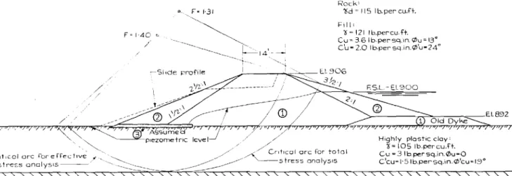
The first stage of the Seven Sisters Falls Hydroelectric Project, completed in 1931, required the construction of earth dikes with a maximum height of 7 to lOft. The second stage, completed in 1949, involved raising the dikes approximately 14ft. as shown in Fig. I.
During the second stage of construction some minor slides and settlement occurred at a few locations. These were the result of steep construction slopes or other unusual conditions and consequently did not cause undue concern for the overall stability since it was assumed that the foundation would increase in strength as a result of consolidation. However, during the
1 Old Dyke
Highly ptos ticclay'
0=105 Ib.percu.ft. Cu=3 lb.persq.in.¢u=O c'cu-1·5Ib.persq.in.¢'eu=1.3° F.SL-E.1.900 セGi Rocke セ、 セ 115 Ib.per eu.H. Fli I' oセ 121 Ib.pereu.ft. Cu> 3.6 Lb.per-eci.m.¢u=13" C'u-Z.O Ib.persq.in.¢'u-24· F·1·31 ,--51,deprof;le 3 Assumea "'---=-plezometnc level ../ fセ 1·40 " / LEGEND 0)-Clay - CI to CH. @-Roek. @-Filter.
Low to medium plastic clay
-
r--- r---
Ia 10 20 30
Scale - feet
Fig. 1 Seven Sisters-typical cross-section and cntical arcs Seven Sisters-coupe et courbes critiques de glissement
348
first indication of a slide is generally the formation of a crack on the waterside of the dike crest. Initially there is no sign of vertical displacement but as the movement progresses settle-ment occurs and a crack up to I ft. wide develops over a length of 100 to 400 ft. During a period of several weeks a scarp I to 6 ft. high generally forms between the dike centre line and the waterside shoulder. In some cases there is an upheaval on the landside toe but generally these signs are subtle and difficult to observe because of the rough terrain. Observations of con-tinuous cores from the slide areas have not disclosed the position of the sliding surface.
None of the slides that have occurred to date have been of a serious nature since there was no immediate threat of a breach. All slides have been stabilized by the addition of a berm, the most economical being approximately one-quarter the height of the dike and 40 to 50 ft. wide. In some cases sand drains have been used.
Foundation-s-The foundation consists of highly plastic clay
to depths of 10to 20ft., underlain by a clay of low plasticity or bedrock. The highly plastic clay has the average properties shown in Table I. It exhibits a nugget structure to a depth of approximately 3 ft. and from 3 to 7 ft. laminations or fissures oriented in the horizontal direction are evident. This is thought to be a result of the formation of thin ice lenses within the clay. Below a depth of 7 ft. this phenomenon has not been observed but some stratification and silty layers are evident.
Table I
Average properties of foundation and dike materials Proprietes moyennes des materiaux pour fondations et digues
Material Property Average Range Number
of tests
Highly plastici Water content 45 19-66 551
foundation ' Liquid limit 85 50-121 191
clay Plastic limit 26 16-40 191
Wet density lb./cu. ; 104 92-ll7 90
i ft.
Low to mediumIWater content 21 14---39 105
plastic found-. Liquid limit 31 23--40 50
ation clay
i
Plastic limit 13n-is
50Fill material I Water content 26 10--49 188
ILiquid limit 55 19-1l4 78
Plastic limit 20 ll-38 78
Wet density lb./cu. ; 123 105-140 55
ft.
It has been found, by averaging water contents of the foundation clay over various depths, that most of the failures occurred in areas where the average water content of the 0 to 8 ft. layer exceeded 45 per cent.
The shear strength of the foundation as listed in Table 2 was obtained by the following methods:
(1) Laboratory unconfined compression tests conducted on specimens from 3 in. diameter thin-walled tube samples;
(2) Field unconfined compression tests conducted on speci-mens obtained from 1 in. diameter thin-walled tube samples;
(3) Field vane borer.
The results in Table 2 include unconfined compression tests obtained from chunk samples which were taken in the zone exhibiting the nugget and fissured structure.
Material Method oftest Property Average Range Numberof tests
Highly Laboratory Shear 9·6 5,9-14'2' 40
plastic unconfined strength founda- from3in.1> lb.rsq. in.
tion clav
-
samples Water con- , 45·1 30,2-57'7 ' 40,
tent
Field uncon- Shear 6·8 3,7-12,6 20
fined from strength
1in.1> lb./sq. in.
23'7-55'91
samples Water con- 43·5 20
tent
Vane borer Shear 12·8 , 4'0-26'01 25
strength
lb.rsq.in.
1-19-Highly Laboratory Shear 4'9 2,8-7,7
plastic unconfined strength
founda- from chunk lb./sq. in. I
tionclay, samples Water con- 44·4 42·1--46'7
i
19depth0- : tent
8ft.
Fill Laboratory Shear 18·0 112-6--42-41 II
material unconfined strength from 3 in. lb.rsq. in.
ll'9-34'7 1
c/>samples Water con- 25·2 Il tent
Field uncon- Shear 13'1 6'0-19'81 6
fined from strength
1in.1> lb.rsq.in.
samples Water con- 24·7 ' ll'5-55'3 6
tent
- - - ,
I
Vane borer Shear 14·5 7'1-20'9r 11
I strength
lb.rsq. in.
In an attempt to determine the effect of the fissured structure upon the strength a number of direct shear tests were con-ducted with the fissures oriented parallel to the failure plane and at 45 degrees to the failure plane. No significant variation in the strength was observed.
Quick and consolidated quick triaxial tests with pore pressure measurements, believed to be representative of the foundation strength for the typical stability analyses presented, are shown in Fig. 2. The sensitivity of the clay lies between 1 and 2.
The low to medium plastic clay underlying the highly plastic clay has average properties as shown in Table 1. The average shear strength as determined from unconfined compression tests was23lb.rsq.in. at an average water content of 15 per cent.
Fill-The dikes were constructed of medium to highly plastic clay with water contents 5 to 10 per cent above the Standard Proctor optimum water content. The density was, in general, greater than 90 per cent Standard Proctor density. Tables 1 and 2 show the average water contents, limits, densities and shear strength for the dikes.
The Mohr envelopes for quick triaxial compression tests with pore pressure measurements are shown on Fig. 3. The strength envelope assumed is shown as a dashed line.
Stability analyses-Across-section with the most critical arcs
for both total and effective stress analyses is shown in Fig. 1.
Using the strengths believed to be representative of this area a factor of safety of 1·3I was obtained by the total stress method and 1·40 by the effective stress method.
10 20 120 110 100 90 i i :
,.J--t=
! i ,t _ セゥ 7't-- Iセケ
i
GMセy
I " ' " i1/
i
I / ' \ I \i /
i 'r\1
tiL"
II
I I _.+ - ,MMKセMMMKMMMKMNT\
-30 20 10CONSOLIDATED QUICK TESTS
I!
l
I I II I I
I I I
:Ccuセ 1'9 Ib.ゥpBG・[イイセウアアZNイイゥョセN
-Ti-Til----=:t2i::Gq5/--j-t:74-11
IG|ゥMMイMセB|tゥ I¢cu=11'60_ _V
I
Bセゥ
MZZウ[[M]ZセNNNNM
i
f\0
I
o
rIft-f'IIi \1(( I "
セGH
\
|セ
jlMMlMMMMMlNNjlMNlMMNセMMMMャlNMMMBMMMMBMMNMGMMMMlMNNMjNNNャMNNNj
o
40 50 60 70 80 120Total Normal Stress -Ib.persq.in.
3u (/I Ul • VC '-""': +-0" (JJ11I l.. L--0
1i
IIljj .!:-iJlFig. 2 Seven Sisters-foundation material strength envelopes SevenSisters-s-courbes intrinseques,materiaux de fondation
QUICK TESTS WITH PORE PRESSURE Mt::ASUREMENTS
Fig. 3 Seven Sisters---embankment material strength envelopes Seven Sisters-e-courbes intrinseques, materiaux de barrage In an attempt to explain the high factors of safety, a corre-lation between the occurrence of slides and the precipitation was attempted, pore pressures were measured and the creep effect (CASAGRANDE and WILSON, 1953) investigated. None of these appeared to have any significant effect on the stability.
North Ridge Dam
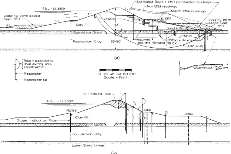
The major portion of this 70 ft. high dam was constructed in a 10 week period between late June and mid-September 1953. When it was nearing completion (Fig. 4a) a foundation move-ment occurred. The fill construction was immediately stopped and loading berms added at the toes. An investigation, in-cluding more detailed drilling and testing, was conducted and additional observational apparatus was installed. The dam was successfully completed in 1956 with no further modifi-cations in design.
Description of movement-The visible indications of the
movement were the appearance of cracks, a slight bulging of the fill, and an overthrust at the downstream toe. The widest cracks were found to be II ft. deep along the upstream slope and 22 ft. deep along the downstream berm. They were up to 6 in. wide at the top and became narrower with depth. They were essentially vertical and there was no evidence of vertical displacement across them. The ground surface for 60 ft. beyond the toe heaved and moved outward about 3 ft. The movement along the surface of the downstream berm (El. 3332) was 4·4 ft. horizontally and 0·7 ft. downward. The measured foundation settlement during the movement was 1·8 ft., near the centre line.
Embankment materia/-Theembankment was constructed of
lean to medium plastic clay of glacial origin: LL = 25 to 35, PL
=
14 to 21 and PI=
10 to 18. The Standard Proctor dry density was 1141b. per cu. ft. at a water content of 14·5 per cent. The average water content and dry density recorded during construction were 14-4 per cent and 110·51b./cu. ft. respectively. The lower 15 ft. was somewhat wetter and less dense than average.Density tests taken in pits dug after the movement averaged 113 lb.jcu. ft. dry but the average for the lower 15 ft. was much higher, i.e. 118 Ib./cu. ft. The water content of the fill samples ranged from 12 to 16 per cent with an average of 14'6 per cent. The quick and consolidated quick strength of fill samples showed considerable variation with a few per cent change in water content. The quick strength of the embankment corre-T I I J j t I I : I t I ..L \0 20 30 40
Ef"f"ectlve Norma I Stress - ib.persq..n.
20i I I I t , ! I I I I I I I I I l...!--I-" I I I t i...-:---+- I セ」
__--on
t i I l l i 1Il'-: • !-. 0" セ . I t '-r-I--'" I I セ tIl イcオ]ZSᄋVi「Nー・イウアNャョNセ t ' i ! セ8.
IO i¢ u 13" i - - - r - ' セ⦅NャZゥ L I' ⦅OセNNNNN[ZM ... ---セ 't.;..:::;"'" T •has been computed by the total stress method of analysis. The strengths used for the foundation clay have been taken from the water content strength relationship developed from several failure areas. Where the water content profiles have indicated more than one layer appropriate strengths have been chosen for each layer. The factors of safety obtained ranged from 0·9 to 2'1, the average being 1·5.
value appeared to be
c;
= 6·0lb.rsq, in and<p'u
= 29 degreesFoundation-The foundation consists of 10 to 19 ft. of fine
silty sand and 35 to 50 ft. of highly plastic clay overlying a fine to medium sand. The transition zone between the upper sand layer and the clay has thin layers or lenses of silt and sand and the upper half of the clay has fragmented layers having the appearance of •cottage cheese'. Piezometers installed im-mediately after the movement revealed high pore pressures only in the clay, particularly the upper portion. These pressures dissipated slowly until by March 1956 they were generally below the fill surface (Fig. 4a).
Laboratory tests on foundation samples gave the following results.
Upper sand layer:Yd
=
97·5 lb./cu. ft. at w=
22'7 per cent.Shear strength,Cd
=
0,<Pd=
29 degrees.Highly plastic clay layer:Y«
=
83·5 lb.rcu. ft. at w=
36·5 per cent, LL=
72, PL=
21.Quick shear strength, Cu
=
8·0 lb./sq. in. <Pu=
0 degrees.Consolidated quick shear strength, C
eu
=
4·3 lb./sq. in.4'eu
= 14 degrees.Effective shear strength from consolidated quick shear strength tests with pore pressure measurements c'cu
=
3·6 lb.per sq. in. and
<p'eu
=
21·8 degrees.bankment cross-section as it existed at the time of movement. Using quick shear strengths and total stresses the minimum factor of safety on a circular arc (MIS-Fig. 4a) was 1·23. By assuming a 22 ft. deep vertical crack (dry) this value was reduced to 1·20. An analysis was also made using effective stresses and the effective strength offill and foundation obtained from triaxial tests with pore pressure measurements. The total normal pressure on the portion of the arc through the fill was reduced by the estimated pore pressure as determined from consolidation tests on typical samples (HILF, 1948; SHANNON, 1955). The factor of safety obtained, assuming no increase in effective pressure in the foundation clay due to the weight of fill, was 1·14.
The composite surface of sliding (sliding block) method of analysis was also used because the movement appeared to be
lateral rather than rotational. A thin horizontal cohesionless layer (c'
=
0;<p'
= 29 degrees) was assumed to exist in the upper part of the foundation clay. Analyses were made for various pore pressure conditions in the foundation clay and along the horizontal cohesionless layer. The strength of the foundation clay and the embankment were based on the effective strengths as determined by the triaxial tests with pore pressure measurements. The total stress in the fill was reduced by the estimated pore pressure as determined from consolidation tests on typical samples. The calculated factor of safety with 100 per cent uplift pressure in the foundation clay and along theounaa IonSdnd
,,-[shmated Sept. 1,1953 ore z.orneter- readings :' ,.r-Nov 1953 readings
7
/ ... "" Mor-en 1956 readings /Clay Fili
FS.L.-[I.3359
Four-icio-t.or-i Clay
Loading berm added
Sept. QYUSセL -, ...: : -."
r
R is eIn p.ez.ornetr-k; level durIng 1955 cor-str-uc non. Piezometer Piezometerr.o (0) I""""'! 1""""1 1""""1 o 20 40 60 80100 Scale - feet/
/
j
セ
Foundation n Foundation Clay RD\67D
Cloy Fill ...:.:: : ,...:LowerSand Loyer
RDI68
Slope Indicator Pipe
F.S.L. - EI. 3359
(b)
Fig. 4 North Ridge-embankment cross-sections North Ridge-s-coupe du barrage
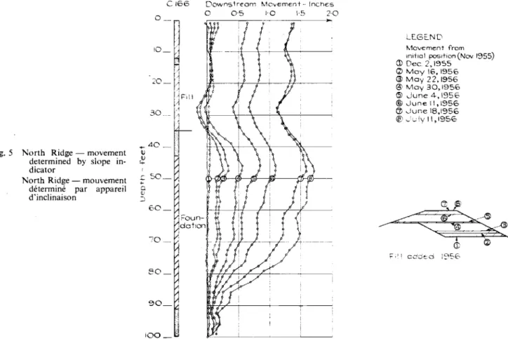
Fig. 5 North Ridge - movement determined by slope in-dicator
North Ridge - mouvement determine par appareil d'inclinaison
CI66
1 0 0 _ '
Downstream Movement- Inches
o 0"5 1'0 \·5 2·0
LE.GE-ND
セQッカ・ュ・ョエ from
n-unc1position(Nov 1955)
CD Dec2,1955 Q)May16,1956 @May 22,1956 @May30,1956 (51 June4-,1956 ®-.June 11,1956 CV-.June 18,1956 ᆴセGオAケャャLQYUV
assumed cohesionless layer, due to the weight of fill, was less than unity (M13-Fig. 4a). The computed factor of safety was 1·06 for piezometric conditions estimated to have existed just before the movement began (1-9-1953-Fig. 4a).
Thesc calculations show that, if a cohesionless undrained layer exists in the foundation, failure is more probable along a composite surface of sliding than on an arc. The existence of such a layer is considered unlikely but not impossible. The computed factors of safety along a composite surface of sliding through the clay foundation without a cohesionless layer are approximately the same for the effective stress analysis as those obtained for a circular arc.
Stability studies were also made for the final design cross-section shown in Fig. 4b. The factor of safety calculated on a circular arc using a total stress analysis was found to be 15 per cent greater than at the time of movement. The computed factor of safety along a composite surface of sliding, based on effective stresses and with the piezometric level of the founda-tion clay at the estimated 1-9-1953 level, was 1·4.
Completion of consTrucTion-Theembankment (except slope
protection) was completed in June 1956. Frequent readings were taken on test apparatus and typical changes in pore pres-sure are shown in Fig. 4b.
Previous to this final stage of construction three plastic slope indicator pipes were installed at the drill hole locations shown in Fig. 4b. By means of an apparatus developed by WtLSON (1953) the lateral movement of the plastic pipe was determined. The maximum lateral movement occurred in hole C166 and typical readings have been plotted in Fig. 5.
Conclusions
For the cases analysed, using the data obtained when move-ment occurred, the computed factors of safety varied within the limits of 0'9 to 2·1 for both the total stress and effective stress methods of analyses. The computed safety factors
would have been higher for both methods of analyses if the maximum deviator stress criterion for shear failure had been used, or if the results of vane tests or unconfined compression tests on tube samples had been applied in the total stress method of analysis.
The reasons for the discrepancy between computed and actual safety factors have not been explained. However, the follow-ing would appear to warrant further consideration: the possi-bility of progressive failure having occurred, the compatipossi-bility of the stress-strain characteristics of the foundation and fill
material, the representativeness of the samples used for strength tests (obtained from a limited number of slide areas), the rela-tionship of laboratory rates of strain to field rates, and the applicability of the shear failure criterion used.
Until such time as the stability of dams and foundations in-volving the more plastic clays can be predicted with greater reliability observations of movement and pore pressure must be relied upon to warn of critical conditions.
The wholehearted co-operation
of
Professor A. Casagrande andThe Winnipeg Electric Company is gratefully acknowledged.
References
ARTHUR, H.G. (1951). Design of the earth embankment Falcon Dam and power plant. U.S. Bureau of Reclamation Technical
Memorandum, No.642,p. 15
CASAGRANDE, A., and WILSON,S.D.(1953). Effectsof stress history on the strength of clays. Soil Mechanics Series No.43, Harvard University
- and RIVARD,P..T. (1956). Strength Investigation of Highly Plastic
Clays. To be published by Harvard University Department of
Engineering
HILF,.T.W.(1948). Estimating construction pore pressures in rolled earth dams. Proc. 2nd International Conference on Soil Mechanics
and Foundation Engineering, Vol. 3,p. 234
SHANNON, W. L. (1955). Measurements of Iatcral movements in soils. Ninth Canadian Soil Mechanics Conference, Associate Committee on Soil and Snow Mechanics, National Research Council, Ottawa