Gas supersaturation,
222Rn and CO
2as tracers in karst water
PhD thesis presented to the Faculty of Sciences of the University of Neuchâtel to satisfy the requirements of the degree of Doctor of Philosophy in Science
by
Domagoj Babiċ
Thesis defence date: 25.06.2013 Public presentation date: 09.10.2014
PhD thesis evaluation committee:
Prof. François Zwahlen University of Neuchâtel, Switzerland Thesis director Dr. Heinz Surbeck ETH-Zürich, Switzerland Jury member Prof. Antoine Kies University of Luxembourg, Luxembourg Jury member Prof. D. Hunkeler University of Neuchâtel, Switzerland Jury member
Secrétariat-décanat de Faculté Rue Emile-Argand 11 2000 Neuchâtel - Suisse Tél: + 41 (0)32 718 2100 E-mail: [email protected]
IMPRIMATUR POUR THESE DE DOCTORAT
La Faculté des sciences de l'Université de Neuchâtel
autorise l'impression de la présente thèse soutenue par
Monsieur Domagoj BABIC
Titre:
Gas supersaturation,
222
Rn and CO
2as tracers in karst water
sur le rapport des membres du jury composé comme suit :
• Prof. hon. François Zwahlen, Université de Neuchâtel, directeur de thèse
• Prof. Daniel Hunkeler, Université de Neuchâtel
• Prof. hon. Antoine Kies, Université du Luxembourg, Luxembourg
• Dr Heinz Surbeck Nucfilm GmbH, Cordast, Suisse
Neuchâtel, le 8 août 2013
Le Doyen, Prof. P. Kropf
Après ces quelque quatre années depuis le début du projet, c'est avec plaisir que j'arrive à la rédaction des remerciements. Je tiens à exprimer une réelle gratitude envers toutes ces personnes qui ont permis, de près ou de loin, de mener à bien cette étude.
En premier lieu, merci infiniment à François Zwahlen, mon directeur de thèse, pour m'avoir proposé cette aventure. Sa porte était toujours ouverte et sa bonne humeur salvatrice très motivante. Son expérience et ses idées ont grandement facilité la progression de ce projet. Merci également pour toutes ses petites anecdotes de vie qui vous font repartir avec le sourire. Je n'oublierai jamais l'élégance du marchandage de tapis à Damas.
Merci à Heinz Surbeck, grand spécialiste des radioisotopes dans les eaux souterraines, pour m'avoir fait entrevoir le potentiel des gaz dissous. Sa grande disponibilité, sa jovialité et ses précieux conseils ont rendu plus accessible la complexité de ce domaine. De plus, sa gestion efficace des données m'ont plus d'une fois sauvé la mise quand la situation semblait désespérée.
Je tiens également à remercier Pierre-André Schnegg, concepteur du fluorimètre de terrain, sans qui le travail des hydrgéologues du monde entier aurait été autrement plus difficile. Sa grande disponibilité et sa gentillesse ont toujours été au rendez-vous.
Un grand merci à Roberto Costa, pour son implication de tous les instants. Sa capacité à créer a grandement facilité le suivi de cette aventure.
Ma profonde gratitude va à Steve Gobert, grand connaisseur des Gorges de l'Areuse. Son incomparable soutien logistique et son équipe n'ont rendu que plus agréable ces journées passées sur le site d'étude.
J'exprime mes sincères remerciements à toute l'équipe du projet ALPEAU, en particulier Robert Jenni, Urs Moser et François Godi. Merci pour leur organisation sans failles, leur implication et leur bonne humeur.
Merci à également à Jean-Michel Gobat du Laboratoire Sol et Végétation pour sa disponibilité et sa capacité à rendre accessible ce monde extrêmement complexe qu'est le sol.
J'exprime une grande gratitude envers Thierry Schneider de chez Tetraedre SA, pour son appareillage de mesure et de contrôle à distance.
Brayek, Corinne Carraux-Drey, Sabine Erb-Robert et Gianfranca Cerrito. La bonne humeur des lieux leur doit beaucoup.
Toute ma gratitude va aussi à Bibiane Schlunegger, laborantine au CHYN.
Je tiens à remercier très chaleureusement tous mes collègues et amis, pour la très agréable ambiance de travail. Une mention toute spéciale au mythique troisième étage. Merci à Lorienne Thüler, mon compère du bureau E319 pour son dynamisme et pour avoir transformé les lieux. Merci à Andrea Borghi et Damian Glenz pour leur amitié, leur hébergement stratégique et tous ces fous rires. Merci à Gregory Deman et Lucien Blandenier pour m'avoir accompagné sur le terrain pendant des conditions dantesques et pour leur maîtrise parfaite du burger au BBQ. Merci à Geoffrey Undereiner, Cybèle Cholet, Julien Straubhaar, Pierik Falco, Giona Preisig éminences grises de l'étage et à Christian Moeck, Antoine Bailleux et Paul Bailleux. Merci également à Michiel Pronk, François Negro, Ellen Milnes et Jaouher Kerrou sans qui les pauses café et les soirées de Neuchâtel n’auraient pas eu la même saveur. Merci à ma famille qui m'a toujours soutenu pendant ces aller-retours entre Genève et Neuchâtel.
Un grand merci final à Sofia, ma moitié pour ses encouragements constants et sa présence...
Karst aquifers are among the most important water resources world-wide. Nevertheless, due to their intrinsic properties consisting in fast transport processes and reduced contaminant attenuation capacity, they are proved to be highly vulnerable.
Consequently, it is important to discriminate between water originating from the soil reservoir, the epikarst, the low permeability volume and the freshly infiltrated rainwater. To do so, the Prédernier artificial drainage gallery (Gorges de l'Areuse, Swiss Jura Mountains) was investigated by a combined continuous monitoring of radon, carbon dioxide and total dissolved gas pressure. Electrical conductivity, turbidity, total organic carbon and dissolved ions were also followed. The survey of various seepages spread throughout the drainage gallery, offered the unique feature of allowing to compare the dynamics of natural parameters characterized by different storage origins and watershed scales.
Radon and carbon dioxide are two gases produced in soil, hence their input function is well delimited. They both are characterized by good solubilities and can be dissolved in percolating water and transported to system outlets. Even tough originating from the same production area, these gases have different chemical and physical properties. On the one hand, radon is an inert radioactive noble gas produced through α-decay of radium present in soil and is characterized by a half-life of 3.8 days. It can be used to assess fast transport processes, as after 20 days its concentrations pass under detection limits. On the other hand, carbon dioxide reacts with carbonates on its way down to the saturated zone.
Total dissolved gas pressure (TDGP) represents water vapour pressure in addition to the individual dissolved gases partial pressures. When TDGP in water exceeds the atmospheric pressure, supersaturation occurs. Following a precipitation event, soil air entrapped in pore space, undergoes a newly applied hydrostatic pressure, allowing more gas to be dissolved. Hence, the percolating water acquires a supersaturation signature, which can easily be followed at system outlets.
properties and naturally and abundantly produced in soil or during rainfall events, were used as natural tracers. The temporal variations of their respective concentrations in underground water not only allow to gain valuable information about fast transport processes in karst systems, but also to identify the different water reservoirs contributing to the discharge.
Results demonstrated that the dissolved gases approach, revealed the importance of the soil sub-system with regards to its influence on the recharge of karst aquifers during high-flow conditions, and on the sustainability of its influence to the flow regime. The supersaturation base-level, a soil thickness specific feature, was used as a relevant surrogate to assess the temporal distribution of soil contribution to the selected karst system. Whereas, codependent radon, carbon dioxide and supersaturation peaks depict the influence of soil stored water, enriched in dissolved gases during rainfall events.
1 INTRODUCTION... 1
1.1 AIM OF THE THESIS...1
1.2 KARST AQUIFERS...2
1.2.1 Karst aquifers specificities and main features...2
1.2.2 The infiltration sub-system...3
1.2.3 Soil...3
1.2.3.1 Soil and hydrogeology...4
1.2.3.2 Forest soil...5
1.2.4 The epikarst...6
1.2.5 The unsaturated zone...7
1.2.6 The phreatic zone...7
1.2.7 Physical and chemical properties...8
1.2.7.1 Turbidity...8
1.2.7.2 Total organic carbon...9
1.2.7.3 Electrical conductivity...10 1.3 DISSOLVED GASES...12 1.3.1 Radon...13 1.3.1.1 Radon emanation...13 1.3.1.2 Radon in soil...15 1.3.2 Carbon dioxide...15
1.3.2.1 Factors influencing CO2 emission from soil...16
1.3.3 Supersaturation...17
1.3.4 Use of dissolved gases as natural tracers...18
1.4 STUDY AREA...20
1.4.1 Gorges de l'Areuse...20
1.4.1.1 Climate...21
1.4.1.2 Geology...21
1.4.2 Prédernier artificial drainage gallery...21
1.4.2.1 Geology and hydrogeology...21
1.4.2.2 Soil...23
1.4.2.3 The Prédernier gallery watershed...24
1.5 MEASUREMENT METHODS, SAMPLING AND DATA ACQUISITION...26
1.5.1 Prédernier artificial drainage gallery...26
1.5.2 Turbidity and total organic carbon...28
1.5.3 Electrical conductivity and temperature...30
1.5.4 Discharge...30
1.5.5 Rainfall...31
1.5.6 Radon, carbon dioxide and total dissolved gas pressure...31
1.5.7 Major ions...34
2 RESULTS AND INTERPRETATIONS...35
2.1 WATERSHED OF THE ARTIFICIAL DRAINAGE GALLERY...35
2.1.1 Low-flow conditions from August 2010 to December 2010...35
2.1.2 High-flow conditions from December 2010 to April 2011...38
2.1.3 Low-flow conditions from May to December 2011...40
2.1.4 High-flow conditions from December 2011 to April 2012...40
2.1.5 Low-flow conditions from May 2012 to September 2012...42
2.1.6 General characteristics of the Prédernier artificial drainage gallery...43
2.1.7 Chemical properties of water in the Dev spillway...45
2.2.1.1 Transition to high-flow conditions of December 2010...47
2.2.1.2 Transition to high-flow conditions of December 2011...50
2.2.1.3 General characteristics of the C3 seepage and conceptual model...53
2.2.1.4 March 2010 tracing test...55
2.2.1.5 C3 seepage conceptual model versus tracing test...58
2.2.1.6 Chemical properties of water in the C3 seepage...60
2.2.2 A1 and A2 seepages survey...61
2.2.2.1 Transition to high-flow conditions of December 2010...61
2.2.2.2 Low-flow conditions from April to December 2011...64
2.2.2.3 General characteristics of the A1 seepage and conceptual model...65
2.2.2.4 Chemical properties of water in the A1 and A2 seepages...66
2.3 DISCUSSION...68
2.3.1 The lag phase...68
2.3.2 The soil phase...70
2.3.3 The mixed phase...73
2.3.4 Supersaturation base level...73
2.3.4.1 Implication regarding the contribution of a thick soil...75
2.3.4.2 Implication regarding the contribution of a thin soil...77
2.3.4.3 The Dev spillway survey...78
2.3.5 The dissolved gases approach in a selected porous media aquifer...80
2.3.5.1 The Mont Gibloux study area...80
2.3.5.1.1 Climate...81
2.3.5.1.2 Geology...81
2.3.5.1.3 Local hydrogeology...81
2.3.5.1.4 Description of the followed outlets...81
2.3.5.1.5 Results and interpretations...82
2.3.5.1.6 Conclusion...86
3 CONCLUSION... 89
3.1 DISSOLVED GASES AS INDICATORS FOR SOIL CONTRIBUTION TO A KARST SYSTEM...89
3.1.1 Thin soil cover...90
3.1.2 Tick soil cover...91
3.2 LIMITATIONS AND PERSPECTIVES...93
4 APPENDICES... I
5 REFERENCES... XI
Fig. 1: Electrical conductivity as a function of the concentration of different ions in
separate solution (modified after Rommel 1980)...11
Fig. 2: Radon emanation coefficient and expected concentrations (Surbeck, 2005)...14
Fig. 3: Localisation of the Gorges de l'Areuse study area...20
Fig. 4: Cross section of the Gorges de l'Areuse valley (modified after Meia 1986)...22
Fig. 5: Soil thickness above the drainage gallery...23
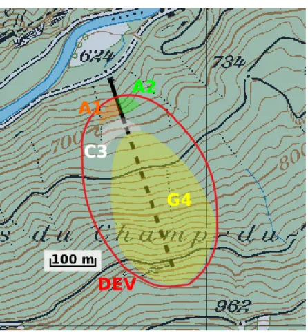
Fig. 6: Estimated watersheds for the A1, A2, and C3 seepages, and for the Dev and G4 spillways...25
Fig. 7: Geology of the southern slope of the Gorges de l'Areuse valley and Prédernier gallery localisation (modified after Meia, 1986)...26
Fig. 8: Prédernier artificial drainage gallery general survey...27
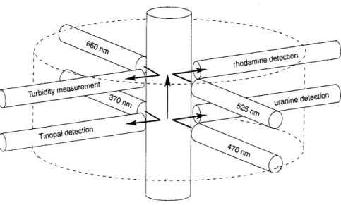
Fig. 9: Excitation and detection units integrated in the GGUN-FL30 field fluorometer (Schnegg, 2003)...29
Fig. 10: Fluorometer mV signal vs TOC [mg/L] in respectively the Dev spillway and the A1 seepage...30
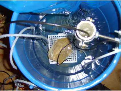
Fig. 11: Closed circuit air-filled semipermeable polypropylene tubing immersed into a collecting can...32
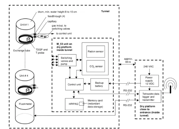
Fig. 12: Radon, CO2 and total dissolved gas pressure monitoring facilities at the Prédernier drainage gallery (Surbeck, 2005)...33
Fig. 13: Radon and CO2 sensors enclosed together with the pump and electronics in a watertight box...33
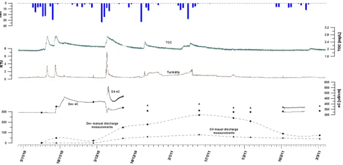
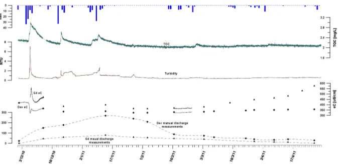
Fig. 14: Manual discharge and eC in the Dev and G4 spillway, along with turbidity and TOC in the G4 sampling point from December 2010 to January 2011...36
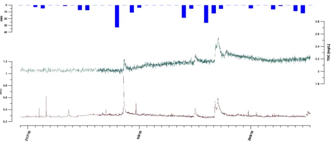
Fig. 15: TOC and turbidity in August 2010 in the Dev spillway...37
Fig. 16: Discharge, eC, turbidity and TOC in the Dev spillway from November 2010 to March 2011...38
Fig. 17: Discharge, eC, turbidity and TOC in the Dev spillway from December 2010 to April 2011...39
Fig. 18: Low-flow conditions in the Dev spillway from April to November 2011...40
Fig. 19: Discharge, eC, turbidity and TOC in the Dev spillway from December 2011 to February 2012...41
Fig. 20: Discharge, eC, turbidity and TOC in the Dev spillway during low-flow conditions from May to September 2012...42
Fig. 21: Discharge apex in the Dev spillway in reaction to soil influence...45
Fig. 22: Piper diagram of samples taken in the G4 spillway between November 11th 2011 and April 12th 2012...46
Fig. 23: Piper diagram of samples taken in the Dev spillway between November 11th 2011 and April 12th 2012...46
Fig. 24: Monitoring of discharge, eC, turbidity, radon, CO2 and supersaturation in the C3 seepage from December 2010 to April 2011. Measurement uncertainties : Rn:~3%, CO2:~7%, supersaturation:~3%...48
Fig. 25: Monitoring of discharge, eC, turbidity, radon, CO2 and supersaturation in the C3 seepage from December 2011 to March 2012. Measurement uncertainties : Rn:~3%, CO2:~7%, supersaturation:~3%...51
Fig. 26: Conceptual flow model of the deep soil contribution to the discharge...54
Fig. 27: Conceptual flow model of the entire soil contribution to the discharge...55
Fig. 28: March 2010 tracing experiment settings...56
Fig. 29: Fluorescein restitution curves in the A1, C3 seepages and in the Dev and G4 spillways...57
Fig. 30: Conceptual model showing underground flow paths...58
Fig. 31: Comparison of dissolved gases temporal evolution with regards to the March 2010 tracing experiment. Measurement uncertainties : Rn:~3%, CO2:~7%, supersaturation:~3%...59
Fig. 32: Piper diagram of samples taken in the C3 seepage between December 2011 and April 2012...60
conditions in December 2012. Measurement uncertainties : Rn:~3%, CO2:~7%,
supersaturation:~3%...62
Fig. 34: Discharge, eC, turbidity and TOC in the A1 seepage during low-flow conditions from March to December 2011...64
Fig. 35: Piper diagram of samples taken in the A1 seepage between November 11th 2011 and April 12th 2012...67
Fig. 36: Piper diagram of samples taken in the A2 seepage between November 11th 2011 and April 12th 2012...67
Fig. 37: Lag, soil and mixed phases in the A1 seepage during high-flow conditions in December 2010...69
Fig. 38: Lag, soil and mixed phases in the C3 seepage during high-flow conditions in December 2010...70
Fig. 39: Supersaturation base level in the A1, C3 seepages and in the Dev spillway...73
Fig. 40: Soil contribution to the C3 seepage from December 2010 to April 2011...75
Fig. 41: Soil contribution to the A1 seepage from December 2010 to April 2011...78
Fig. 42: Soil contribution to the Dev spillway from December 2010 to July 2011...79
Fig. 43: Localisation of the Mont Gibloux study area (modified afted Martini 2012)...80
Fig. 44: Localisation of selected drains (123 and 40) on the southern slope of the Mont Gibloux hill (modified after ABA-GEOL SA, 2006)...82
Fig. 45: Conceptual flow model during moraine aquifer predominant contribution (modified after Martini, 2012)...82
Fig. 46: Dissoved gases in the 40 drain in April 2012. Measurement uncertainties : Rn:~3%, CO2:~7%, supersaturation:~3%...83
Fig. 47: Conceptual flow model during moraine aquifer and soil alternate contributions (modified after Martini, 2012)...84
Fig. 48: Conceptual flow model during moraine aquifer predominant contribution (modified after Martini, 2012)...84
Fig. 49: Dissoved gases in the 123 drain in April 2012. Measurement uncertainties : Rn:~3%, CO2:~7%, supersaturation:~3%...85
Fig. 50: Conceptual flow model during soil predominant water contribution (modified after Martini, 2012)...86
Fig. 51: Conceptual response of a thin soil covered karst system in reaction to rainfalls. ...90
Fig. 52: Conceptual response of a thick soil covered karst system in reaction to rainfalls. ...92 Fig. 53: Discharge calibration in A1 seepage (Keller 1m)...I Fig. 54: Discharge calibration in A1 seepage (Keller 0.2 m)...I Fig. 55: Discharge calibration in A1 seepage (Keller 1m, DT50)...I Fig. 56: Discharge calibration in A2 seepage (Keller 1 m)...I Fig. 57: Discharge calibration in A2 seepage (Keller 0.2 m)...II Fig. 58: Discharge calibration in A2 seepage (Keller 0.2 m, DT50)...II Fig. 59: Discharge calibration at C3 seepage (STS, DL/N 64)...II Fig. 60: Monitoring of discharge, electrical conductivity, turbidity and total organic carbon in the Dev spillway, along with discharge and electrical conductivity in the G4 spillway...IV Fig. 61: Long term monitoring of the C3 seepage, with highlighted non relevant data for dissolved gases analysis. Measurement uncertainties : Rn:~3%, CO2:~7%,
supersaturation:~3%...V Fig. 62: Relevant periods for dissolved gas (radon, carbon dioxide and supersaturation) interpretation in the C3 seepage. Measurement uncertainties : Rn:~3%, CO2:~7%, supersaturation:~3%...VI Fig. 63: Discharge, eC, radon, CO2 and supersaturation in the A1 and A2 seepages. Measurement uncertainties : Rn:~3%, CO2:~7%, supersaturation:~3%...VII Fig. 64: 222Rn in the C3 seepage vs 222Rn in the A2 seepage during low-flow
conditions...VIII Fig. 65: 222Rn in the C3 seepage vs 222Rn in the A1 seepage during low-flow
Fig. 67: CO2 in the C3 seepage vs CO2 in the A2 seepage during low-flow conditions.VIII Fig. 68: Non-relevancy period of dissolved gases in the A1 seepage during low-flow conditions. Measurement uncertainties : Rn:~3%, CO2:~7%, supersaturation:~3%...IX
List of Tables
Table 1: Corrections factors depending on the reference temperature (modified after Rommel 1980)...11 Table 2: Watershed estimated surface area for the Dev and G4 spillways, and for the A1, A2 andC3 seepages...24 Table 3: Overview of the monitoring program in the Prédernier artificial drainage gallery...28 Table 4: Charge balance error for sampled water...III
Appendices
Appendix I: Introduction...I Appendix II: Results and interpretation...IV
1 Introduction
1.1 Aim of the thesis
The Alpeau project1 aims at strengthening the protective role of forests with an eye to the
sustainable management of groundwater resources and their quality. In order to do so, it promotes responsible forest management methods and evaluation of their costs. It is generally admitted that underground water filtered through forest soil is characterized by its excellent quality (e.g. Klapproth and Johnston, 2000). Nonetheless, forest harvesting may drastically impact the soil. Aggressive methods and industrial harvesting, that involves road construction and soil compaction, may noticeably affect the filtering features and storage capacity of forest soil. Indeed, soil compaction results in a decline in macropore flow, a reduced infiltration capacity, a high susceptibility to erosion and a decreased hydraulic conductivity (Zheng, 2008). Moreover, the Alpeau project tends to develop efficient cooperation methods, establishing contractual relationships, between actors of the water providing sector and those of forest management.
In karst aquifer systems, the soil layer is held accountable for an important part of contamination hazards. Therefore, several authors have proposed the monitoring of soil related parameters, such as turbidity and total organic carbon on their own (e.g. Nebbache
et al., 1997; Stadler et al., 2008) and in combination with particle size distribution (Pronk,
2009), as surrogates for the occurrence of microbial contaminations.
This study, which is part of the Alpeau project, intends to assess the relevancy of a dissolved gases approach, to evaluate the soil contribution to the hydrodynamic of the selected karst aquifer. To do so, the selected test site was investigated by a combined continuous monitoring of radon, carbon dioxide and gas supersaturation. Indeed, both radon and CO2 are characterized by a good solubility and are naturally and abundantly
produced in soil, whereas the generation of supersaturation in soil occurs during precipitation events. These gases, along with supersaturation, can easily be monitored at system outlets and were used as natural tracers.
1.2 Karst aquifers
1.2.1 Karst aquifers specificities and main features
A karst aquifer is made of soluble hard rock and is characterized by surface and underground phenomena of chemical dissolution. It is described by a karstified geological unit which contains groundwater. It may form in any types of rock that show some degree of chemical or physical water solubility. The most typical and important karst rocks are carbonate rocks, above all limestone but also dolomite. Gypsum, anhydrite, carbonatic conglomerate and sandstone can also show some karstifications.
Karst aquifers have a very specific structure and behaviour. They may be essentially described by their duality, also known as organised heterogeneity (Perrin, 2003). This heterogeneity can be schematized by a high permeability connected channel network formed by the dissolution of a low permeability fractured limestone unit (Drogue, 1971; Kiraly, 1975). This network drains a catchment basin and discharges to at least one perennial spring.
More specifically, the saturated and unsaturated zones are not necessarily superimposed (Mangin, 1975), hence part of the recharge can come from allogenic or adjacent non-karst areas. As such, the karst system term would be more appropriate than karst aquifer, as it is referred to the entire drainage unit of the system. Furthermore, this duality can also be found in the autogenic recharge conditions which may be diffuse (through the soil, the epikarst or the low permeability volumes), or concentrated (into the channel network or sinking streams). The groundwater flow field follows this duality, as low flow velocities occur in the fractured volume and high flow velocities characterized the channel network. The discharge conditions follow this dual behaviour as well. Indeed, diffuse seepage takes place from the low permeability volume, and concentrated discharge from the karst network at the spring (Kiraly, 1998). Finally, water storage within the system can occur in both the vadose and phreatic zone.
This heterogeneity found in the hydrogeological behaviour of karst systems can be related to the geological and geomorphological features of karst terrains (Ford and Williams, 1989).
Several conceptual models regarding karst aquifers are presented in the literature (Blavoux and Mudry, 1983; Doerfliger et al., 1999; Drogue, 1992; Grenn et al., 2006; Klimchouk, 2000; Lacroix et al., 2000; Lee and Krothe, 2001; Mangin, 1975; Perrin, 2003; Sauter, 1992; Williams, 1983). Although some differences can be found among them, especially considering the origin of the base flow regime (the low permeability volume in the phreatic zone or the epikarst) and the origin of the water contributing to flood events (concentrated or diffuse infiltrations, phreatic or freshly infiltrated water, epikarst, soil or conduit storage, mixing of different tributaries) they all mostly agree on separating karst systems in different sub-systems:
• the infiltration sub-system • the soil and epikarst sub-system • the unsaturated zone
• the phreatic zone
1.2.2 The infiltration sub-system
The infiltration sub-system is defined according to its recharge constituting terrains. If they are characterized by karstic terrains only, it is referred to as a unary karst system and the recharge is said to be autogenic. If karstic and non-karstic terrains contribute to the re-charge (allogenic rere-charge) it is known as a binary karst system.
1.2.3 Soil
Soil may be described as a three phases system: soil solid (minerals and organic matter), liquid and gaseous phase. It is the result of the alteration and the reorganisation of an underlying bedrock. Both these transformations are the direct consequences of biological activities and atmospheric influences (Aubert and Boulaine, 1980, in Lozet and Mathieu, 2002). It is generally referred to as soil pedogenesis. It can be described by three successive stages (Tissier, 2012).
The first stage consists of underlying rock physical and chemical alteration. The former is the result of temperature variations, wind erosion and plants growth (especially root impact). These phenomenons lead to the formation of soil skeleton referring principally to
altered rock, gravels, sand grains and silt particles. The latter implies rock dissolution and hydrolysis under the influence of acid and alkaline enriched water. This process leads to the generation of alteration features such as silt and iron-oxides.
The second stage is characterized by organic matter enrichment. Newly formed soil is colonized by pioneer plants and animals. Following their decomposition by microorganisms and fungi, humus formation occurs and CO2 is released. Under the influence of CO2 and
water, rock alteration continues.
The third stage can be referred to as horizons formation. Depending on the total amount of precipitations, soil permeability and humus features, leaching takes place within soil. It results in soil horizons formation. These horizons are quite homogeneous, parallel to the surface and are characterized by their thickness, grain size distribution, alkalinity and rock alteration levels.
In this study, soil stands for the unconsolidated pedologic cover of a limestone bedrock.
1.2.3.1 Soil and hydrogeology
Perrin (2003) demonstrated the prominent role of the soil cover with regards to storage and transport processes through the unsaturated zone of karst aquifers. Indeed, soil influences the infiltration and the mixing of solutes. Following an isotopic survey of percolation water (δ18O) at the Milandre cave (Switzerland), an area covered wit thick soil,
he suggested that significant mixing occurred in the soil zone, as the rain isotopic signature was highly buffered when reaching the unsaturated zone underneath.
Pedogenesis in the Jura mountains is strongly controlled by the underlying bedrock (Gaiffe and Bruckert, 1990). In some loacations loess plays a role as well (Havlicek and Gobat, 1996). As a result, two principal types of soil cover can be found in these areas: brown soils and humo-calcic (Calco soils) ones. Those soils present different features. Brown soils are found on solid limestone characterized by a low fracturing density (e.g. dolomitic and marly limestone, dip slope strata). Therefore, they are poorly drained and have a high humidity level. Humo-calcic soil develops on well fissured limestone. They are efficiently drained, thus have a low storage capacity. They contribute to significant calcium level in water as rock fragments are usually found. Aubert and Pochon (1977) compared these two soil types water chemistry. They obtained a mean concentration for bicarbonate and calcite ranging from 12.5 to 21.7 mg/l for the brown soils, and from 47.2 to 126.3 mg/l for calco-humic soils. Hence an observed diminishing mineralisation at a karst spring doesn’t
necessarily mean a contribution of fresh infiltrated water, but could also show a brown soil zone influence.
1.2.3.2 Forest soil
It is generally admitted that underground water filtered through forest soil is characterized by its excellent quality (Davie, 2006). This can by explained by the fact that forest ecosystems are well preserved and rarely under influences of human activities and pollution, contrary to pastures and urban areas. Moreover, if any accidental spill was to happen forest soil is naturally rich in organic matter and hence efficiently minimises pollutions. Following precipitations, water will first percolate through the humus layer, described as the upper part of soil containing organic matter and highly influenced by biological activities (AFES, 2009). It is the soil horizon which is most likely to be subjected to human influences (Gobat et al., 2010). The chemical and physical filtering role of this soil is achieved through the combination of high organic matter content and a diversified and dynamic biocenosis. Indeed, several natural processes, such as sorption, denitrification, oxydoreduction, ions exchanges and plant nutrient intake take place (Klapproth and Johson, 2000; Schürch et al., 2003). Microorganisms turn out to be of significant importance (Gish et al., 1998). They degrade organic matter and are involved in denitrification. All these statements can be considered to be true in “naturally” or “ethically” harvested forests. Moore (1999) links aggressive harvesting methods with significant high sediments loads and pesticides presence in surface and underground streams. Industrial harvesting, that involves road construction and soil compaction, seems to be a particularly ravaging result (Aust and Blinn, 2004), as pollution can occur and the filtering features of forest soil is drastically affected.
In contrast to Perrin's work, Lange et al. (2008) underlineded the role of preferential flow paths through the soil. These preferential flow paths can be directly related to vegetation and especially tree roots, as a densely developed tree roots network enhances the transport of water underground. Concentrated infiltration can also occur following tree trunk water accumulation (Gobat et al., 1998). Bundt (2000) points out two mechanisms allowing rapid movement of water and solutes that bypass a portion of the soil matrix. The first one is known as macropore flow. It generally occurs through root channels, cracks and fissures and other biopores (Beven and Germann, 1982; Booltink and Bouma, 1991; Jacobsen et al., 1997). The second one is referred to as finger flow. It takes place trough
macroscopically homogeneous soil in reaction to a wetting front contrast due to differences in water content, trapped air, water repellency of solid surfaces or inhomogeneous infiltration at the surface (Glass et al., 1989; Selker et al., 1992; Dekker and Ritsema, 1996).
It could easily be assumed that macropore flow could promote underground water pollution. However, the danger is only hypothetical, as macropores are characterized by high oxygen and organic matter content, resulting in flourishing microbial activity (Gish et
al., 1998).
1.2.4 The epikarst
Klimchouk (1997) defined the epikarstic zone (also referred to as subcutaneous zone) as the uppermost part of exposed karstified rocks. The permeability of this zone, which is the consequence of fissuring and diffuse karstification, is noticeably more important than the one characterizing the underlying vadose zone. Rock decompression and biochemical processes (dissolution and vegetation fissuring) result in an exponential increase in fissure density towards the rock ground surface.
The epikarstic zone structure and functioning has been described by several authors (Williams, 1985; Smart and Friedrich, 1986; Klimchouk, 2000). At the surface and within the uppermost part of the epikarst, vertical hydraulic conductivity is high and quite homogeneous. Consequently, diffuse infiltration is a dominant feature. Moreover, hydraulic conductivity drastically diminishes with depth in reaction to jointing density and diffuse karstification lessening. As a result, even though infiltration is efficient in the upper part of the epikarstic zone, drainage out is more problematical leading to water storage. These distinctive features can be summarized as a permeability contrast between the epikarstic zone and the underlying low permeability volume, leading to the formation of a perched aquifer. Water flow in this perched aquifer is characterized by a noticeable horizontal component which allows recharging of the vadose zone through the nearest vertical fissures. The epikarstic zone can thus support base flow and concentrates water fluxes into the uppermost part of the unsaturated zone (Jeannin, 1996).
Nevertheless, all the above described features are known to be true for mature epikarsts. According to Klimchouk (2004), interruption of epikarst maturation by glacial stripping is
zone. The removal of the epikarst changes drastically the hydrological behaviour of the post-glacial karst system. The new epikarst zone tends to re-establish after glaciations, and its evolution follows a typical young epikarst stage. He states that a poorly developed epikarst is characterized by a low to negligible water storage capacity and mainly behaves as a flow concentrating media. Most of karst massifs that experienced glaciations during the last glacial maximum have the epikarst re-establishing on young stages.
1.2.5 The unsaturated zone
The unsaturated zone, also referred to as the vadose zone, connects the epikarstic sub-system and/or the soil to the phreatic zone. This transfer is mostly achieved by drainage through a vertical network of fissures and conduits, also known as concentrated or quick flow. Seepage flow through the low permeability volume (LPV), the rock matrix and the fractured limestone, also occurs. Indeed, Kiraly (2002) thanks to numerical simulations, estimated that 50% of water transiting through the vadose zone, does so in drainage conduits. These two types of flow lead to two hydraulic responses at karst systems outlet. Conduit flow leads to nervous hydraulic behaviour and seepage flow through the low permeability volume results in a more attenuated signature. The combination of these two hydraulic reactions lead to what is usually observed at karst systems sources. It is relevant to point out the unsaturated zone storage feature. During heavy flood events, fresh water may recharge the low permeability volume in reaction to a hydraulic gradient inversion. This matrix storage can then contribute to base flow recharge during low flow conditions (Emblanch et al., 1998).
1.2.6 The phreatic zone
The phreatic zone, also named the saturated zone, can be described as a network of high permeability conduits within low permeability volumes characterized by a high storage capacity. It is the main storage unit of karst systems. The main part of flows occur in the drainage conduit and are known to be turbulent, whereas storage is mainly concentrated in the fractured limestone (White and White, 2005). A hydraulic gradient inversion between the conduits and the matrix during precipitation events recharges the low permeability volume as well. This inversion stops the contribution of the phreatic zone storage to spring discharge (Kiraly, 1998).
The saturated zone is sometimes overhanged by a so called epiphreatic zone, which can be partially saturated in reaction to floods or during high-flow conditions (Monroe, 1970).
1.2.7 Physical and chemical properties
1.2.7.1 Turbidity
The turbidity of water is a measure of the extent to which the intensity of light passing through is reduced, by absorption, diffusion or reflection, by suspended matter. The turbidity of underground water is the result of suspended particles, such as insoluble minerals, colloids originating from soil erosion, micro-organisms and organic particles resulting from the decomposition of plant and animal remains. Typical diameters range from less than 1μm for colloids to more than 1 mm for other particles. The index of refraction of water, the size and shape of suspended matter influence light diffusion. PH can also noticeably affect turbidity. Indeed, some substances can flocculate in reaction to the variation of these parameters.
In porous aquifers, turbidity content is generally low and quite stable in time. This behaviour is not observed in karst aquifers, prone to nervous system responses, where particles transport, implying turbidity presence, is a complex process involving sedimentation and suspension phenomenons (Fournier et al., 2006). Indeed, limestones alteration and soil leaching result in the genesis of silt, which settles down after a discharge diminishing in the conduit network. Particles characterized by a larger diameter are more prone to settling down and sedimentation, as well to remobilisation following discharge variation within the intrakarstic conduit network. On the one hand, turbidity events occurring at karst springs, known as autochthonous turbidity, results from the resuspension of intrakarstic material; on the other hand, allochthonous turbidity is the consequence of direct transfer of particles from the soil or sinking surface streams (Amraoui et al., 2003; Lacroix et al., 2000; Mahler and Lynch, 1999; Massei et al. 2003; Pronk, 2009). Several authors have proposed turbidity as a surrogate indicator of microbial contamination (Nebbache et al., 1997; Ryan and Meinman 1996). However, according to Kralik (2001), even though small turbidity events sometimes coincide with bacterial contamination, large turbidity variations may happen without any bacterial presence. Thus, the duality of turbidity origin, whether it is autochthonous or allochthonous, and the lack of clear microbial contamination correlation, doesn't allow turbidity alone to be used as a reliable water quality indicator (Dussart-Baptista et al., 2003).
1.2.7.2 Total organic carbon
Natural organic compounds found in groundwater generally originate from the soil layer (Batiot et al., 2003). On occasion, organic rich layers within aquifers also contribute to organic content. The natural organic compounds are mainly the result of decomposition of plants material by microorganisms. The fraction available for transport across the unsaturated zone is usually refractory (i.e. difficult to degrade), if not, it would be degraded by the time it reaches the phreatic zone and the system outlet. Natural organic particles are a complex combination of different molecules with variable composition. Each individual compound is very difficult to isolate and identify. Therefore, the content of organic matter is often characterized globally and referred to as dissolved organic carbon (DOC) or total organic carbon (TOC). Total organic carbon includes dissolved and particulate organic carbon (POC). Particulate organic carbon doesn't represent a significant part of total organic carbon (Thurman, 1985) in natural media. Dissolved organic carbon can thus be used as a surrogate for total organic carbon. According to its size distribution or its solubility at pH values, dissolved organic carbon is subdivided into different classes. Indeed, a common way to characterize DOC is to determine its fulvic and humic fraction, which belong to the group of humic substances. The fraction of humic substances insoluble in water at pH=2 but soluble at higher values is known as humic acid. On the contrary, fulvic acid is soluble under all pH conditions.
Total organic carbon (TOC) principally originates from the soil and surface water and is typically of allochthonous origin (Batiot et al., 2003). Stadler et al. (2008) proposed it as an “early-event” warning surrogate for real-time monitoring of microbial contamination. Savoy (2007) underlined TOC propensity to behave as a solute in karst aquifers. Indeed, TOC signal at the system outlet, is not always synchronous with a bacterial peak and often trails behind (Auckenthaler et al., 2002). In the simplest and most optimistic case, a combined increase of turbidity and TOC indicates the arrival microbial contamination. However, even a very low increase of both parameters, even below the water quality standards, may coincide with high allochthonous bacteria levels (Pronk, 2009). As a result the use of both these parameters as surrogate for water microbial contamination may appear problematical.
1.2.7.3 Electrical conductivity
The in situ measurement of the electrical conductivity (eC) is a common approach to characterize the total content of dissolved compounds in water. A strong correlation can usually be observed between the electrical conductivity and the total amount of dissolved compounds. Indeed, most dissolved particles are usually electrically charged. Water mineralisation directly depends on the different lithologies crossed along the flow path and on the transit time. Calcium and bicarbonate strongly influence measured electrical conductivity values (OFEV, 2009). In karst systems, their content variations, so water electrical conductivity, enhance different water contributions, whether it is during high flow or low flow conditions (Fournier et al., 2006). Dilution by storm events water, low mineralized water from some type of brown soil and temperature can noticeably influence electrical conductivity values. Indeed, a negative shift in conductivity values can be used as a surrogate for freshly infiltrated water (Massei et al., 2003).
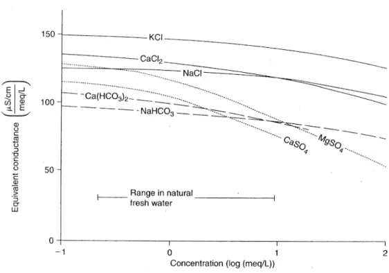
The relationship linking mineral concentration and electrical conductivity varies depending on the type of ions present in the solution (Fig. 1). The electrical conductivity per amount of compound depends on how concentrated the solution is. For Ca-HCO3 waters, the conductivity of a solution containing 1meq/L Ca 2+ and 1meq/L HCO
3- is about 100 μS/cm.
Thus 80 mg/L of dissolved compounds per 100 μS/cm of electrical conductivity can be expected at 25 °C. The electrical conductivity strongly depends on the temperature, as an increase of 2% is observed per °C. The precise relationship between temperature and conductivity depends on the considered temperature range and the water composition. Usually, the electrical conductivity is reported for a temperature of 25°C or 20 °C. If measured at a different temperature, it has to be transformed to a referenced one. It can be converted as follows:
EC
R=
EC
1+
α
R100
⋅(
T −T
R)
ECR → Electrical conductivity at reference temperature TR (e.g. 25°C)
EC → Electrical conductivity at temperature T
αR → Correction factor: Percent variation of EC per °C depending on the reference
Temperature °C α20 EC/EC20 α25 EC/EC25 0 2.09 0.582 1.91 0.522 5 2.14 0.679 1.96 0.608 10 2.19 0.781 2.00 0.700 15 2.24 0.888 2.04 0.796 20 2.28 1.000 2.08 0.896 25 2.32 1.116 2.10 1.000 30 2.35 1.235 2.14 1.107 35 2.38 1.357 2.17 1.217
Table 1: Corrections factors depending on the reference temperature (modified after Rommel 1980).
Fig. 1: Electrical conductivity as a function of the concentration of different ions in separate solution (modified after Rommel 1980).
1.3 Dissolved gases
When a gas phase is in contact with water, some of the gaseous molecules dissolve. The partial pressure of the gas in the gas phase and the equilibrium concentration of compound in the aqueous phase are related by the following equation known as the Henry's law:
K
h=
C
w ,ip
iwhere pi is the partial pressure of compound i in the gas phase (e.g. atm), Cw,i the
concentration of the compound in the aqueous phase (mol/L) and Kh the Henry coefficient
(mol/(L*atm)). In some studies, the Henry coefficient is defined as a dimensionless constant:
K
gw=
C
g ,iC
w ,iwhere Cg,i and Cw,i are respectively the concentration of compounds in the gas and aqueous phase in any units as long as they are the same in both phases (e.g. mg/L, mol/L). Kh and Kgw are related by the following equation derived using the ideal gas law:
K
gw=
C
g ,iC
w ,i=
p
i/
R⋅T
C
w , i=
1
R⋅T⋅K
hwhere R is the gas constant (0.08206 L atm mol-1 K-1) and T is the absolute temperature.
Flow path and transit time of water in a hydrogeological system is of great importance in order to assess the vulnerability of an aquifer. Through time the use of tracers has been developed. Artificial tracers, characterized by a conservative behaviour, are widely used (Kaess, 1998). The clearly defined input function of the tracer and its very accurate detection are some of its biggest advantages. However, without mentioning how time consuming it is to set a tracing experiment, artificial tracers can only be applied over a very localized area and their persistence in the environment makes it quite difficult to repeat
the experiment during different hydrogeological conditions. To bypass these limitations natural tracers can be used. Indeed, they are naturally present and produced over the whole catchment. Environmental isotopes such as 18O, 2H and 3H can give significant insight
into the contribution of water from various origin, such as freshly infiltrated, low permeability volume or unsaturated zone stored water (Katz et al., 1998; Lee and Krothe, 2001; Maloszewski et al., 2002). The main drawback of these environmental tracers is the lack of continuous measurement methods and the complexity of defining an input function.
Turbidity, total organic carbon and electrical conductivity are also used as natural tracers, especially in karst systems, as they allow to define karst system dynamic (Amraoui et al., 2003; Batiot et al., 2003; Massei et al. 2003) and to assess the potential risk of microbial allochthonous contamination in combination with particle size distribution (Pronk, 2009). An elegant way to combine the abundance of natural tracers and the artificial tracers ease of detection and continuous measurement possibility is the use of dissolved gases, such as radon, carbon dioxide and total dissolved gas pressure.
1.3.1 Radon
Radon (222Rn) is a radioactive noble gas produced through decay of radium (226Ra). It is part
of the uranium (238U) decay chain. Three different isotopes are found in nature: 219Rn, 220Rn
and 222Rn. 222Rn, characterized by a half-life of 3.82 days is the most abundant. The two
other isotopes are very short-lived, 55.6 s for 220Rn and 3.96 s for 219Rn, and are not
expected to be transported far before decay. In this study 222Rn will always be referred to
as radon and 226Ra as radium. Radon concentrations are measured in Bq/L. One Bq is
defined as the activity of a quantity of radioactive material in which one nucleus decays per second.
1.3.1.1 Radon emanation
Radon is produced within the grains in rocks and soil. The propensity of radon to escape from the soil grain is known as radon emanation (Grolander, 2009). Emanation is a combination between diffusion, allowing radon to reach pore space within soil grains, making it available for transport through dissolution in percolating water; and alpha particle recoil, which produces simultaneously an alpha particle and a radon atom. This
recoil theory (Semkow, 1990), states that radon atoms produced during radium decay possess a recoil energy, which will allow them to be transported some 40 nm (considering
222Rn) through the rock or the soil grain, permitting them to reach pore space or another
grain. This implies that if radium atoms are situated near or on the surface of the grain, radon emanation is more efficient. The fraction of radon available for transportation is known as the radon emanation coefficient ε. It represents the percentage of produced radon atoms that reaches pore space (Fig. 2).
Several studies focused on radon emanation and transport in soil (Hubbard et al., 1992; Hubbard and Hagberg, 1996, Washington and Rose, 1990; Holkko and Liukkonen, 1993; Washington and Rose, 1992). According to these authors, the concentration of radon within the soil evolves with time, under the influences of atmospheric pressure changes, pressure and temperature gradients, wind and moisture content. Grain composition (Morawska and Philips, 1993), grain size (Markkanen and Arvela, 1992), soil porosity, permeability and compaction (Holkko and Liukkonen, 1993), radium distribution (Greeman et Rose, 1996; Hogue et al., 1997) also affect radon emanation and transport rate. Indeed, the bigger the specific surface area is (small particle size), the more enhanced the emanation will be, as a larger proportion of the radium atoms will be closer to the particles surface. Morawska and Philips (1993), calculated that for a spherical sand grain (r=0.5 mm) without any inner porosity, the radon emanation coefficient is 8000 times higher with a surface radium distribution than with a homogeneous one within the grain. The soil moisture content may also increase the emanation by slowing down radon atoms in the
Fig. 2: Radon emanation coefficient and expected concentrations (Surbeck, 2005)
pore space. The porosity affects it as well, as larger pores diminish the number of radon atoms to enter adjacent grains.
1.3.1.2 Radon in soil
Radon production in soil is far more important than in a heavily fractured limestone, where radium is present in the bulk and not on the surface, and atmospheric radon concentrations are several orders of magnitude below soil gas radon levels (Surbeck, 2005). Well developed soils, where adsorption processes and dissolution phenomenons permit secondary radium accumulation on the surface of soil grains, lead to high radon concentrations. Indeed, several studies underlined the tendency of radium to be adsorbed on iron- and manganese-oxyhydroxides (Ames et al., 1983; Scott and Wiegand, 2003). Moreover, Schwertman (1985) pointed out that these oxides reflect soil pedogenenis and weathering degree. The action of vegetation plays a significant role as well. Radium is cycled by vegetation, as it is retained in the soil and bound in humidified organic matter (Greeman et al., 1990). This means that plants favour high radon concentration in soil gas by maintaining radium concentration in a readily emanating form.
Radon concentrations in soil are also affected by degassing to the atmosphere by diffusion (Climent, 1996). A diminishing of radon levels are thus observed towards the surface, whereas they increase downwards through the soil. These observations were corroborated by Savoy (2007) who, in addition, observed the highest concentrations at the soil/epikarst interface.
Even though some radon from deep down could be involved in soil overhanging uranium rich igneous rock (Grolander, 2009), this is not really probable, especially over a karst system. Indeed, limestone is a poor radon source, as low radium concentrations were measured in Swiss Jura Mountains samples (10 Bq/Kg), with radium present in the bulk and not at the surface (Surbeck, 2005). That implies a very low production and emanation coefficient.
1.3.2 Carbon dioxide
Carbon dioxide (CO2) is mainly produced in soil. It is accounts for more than 20% of total
carbon dioxide emissions to the atmosphere (Rastogi et al., 2002). According to Surbeck (2005), the mean CO2 concentration in soil is twenty times higher than the one measured in
the atmosphere, respectively 1%Vol and 0.04%Vol. It is released from soil through soil respiration, which involves three biological processes: microbial, root and faunal respiration. These three processes principally occur at the soil surface or within the upper layers where the bulk of plant residual matter is concentrated. Soil microbial population contributes up to 99% of total CO2 resulting of the decomposition of organic matter.
About 50 % of this microbial CO2 production happens within the plant roots system
(Macfadyen, 1970). As for faunal respiration, it only contributes to less than 1% of total soil emissions.
1.3.2.1 Factors influencing CO2 emission from soil
Temperature noticeably influences CO2 emission. A strong correlation between mean daily
litter temperature and CO2 evolution was observed (Edward, 1975). Indeed, seasonal CO2
flux is highest in spring and summer, as the biological activity is high and organic decomposition efficient.
Soil moisture content affects soil respiration and therefore CO2 evolution as well. An
increasing soil moisture content intensifies CO2 release up to an optimum level, above
which it diminishes (Johnson et al., 1994). Besides, following a dry period, a newly remoistened soil increases microbial activity and is accompanied by release of air in the soil pores contributing to CO2 variation. Furthermore, under dry soil conditions, soil microbial
respiration is stronger during the day than at night, while day and night respiration is very similar when soil is wet, which involves a reduction of soil temperature variability under wet conditions (Grahammer et al., 1991).
Atmospheric pressure change also plays a noticeable role controlling CO2 emission from
soil. On the one hand, it was observed that atmospheric pressure is inversely related to CO2
release from soil to the atmosphere (Moore and Dalva, 1993). On the other hand, CO2
dissolution in water is directly linked to atmospheric pressure, as high pressure allows more gas to be dissolved.
Nonetheless, these statements are not true, especially in karst systems flows outside the soil zone, where limestone dissolution by CO2 and degassing involves a diminishing of this
gas concentration in percolating water from the soil down to the system outlet. The dissolution of calcite can be expressed by the following equation:
-1.3.3 Supersaturation
TDGP (total dissolved gas pressure) represents water vapour pressure in addition to the individual dissolved gases partial pressures. As oxygen and nitrogen are the dominant components in outside air and are well soluble, they mostly contribute to the TDGP in percolating water. When TDGP in water exceeds the atmospheric pressure, supersaturation occurs. This phenomenon is also known as “excess air”. It is measured by subtracting the atmospheric pressure to the TDGP in water and is expressed as [mbar]. The formation of excess air is usually linked to the complete or partial dissolution of entrapped air bubbles in the soil under the influence of the hydrostatic pressure (Heaton and Vogel, 1981). Except for air naturally present within soil pore space, air entrapment may occur following water level fluctuations (Faybishenko, 1995).
Holocher et al. (2002) studied the formation of supersaturation in quasi-saturated media by analysing dissolved noble gas concentrations in laboratory column experiments. Two types of experiment were set up. The first one simulated groundwater recharge by a vertical water flow through the column, whereas the second one tried to reproduce the behaviour of groundwater level fluctuations. Several physical constraints controlling the formation of excess air were identified.
The dominant parameter is the pressure, as the hydrostatic pressure in combination with the capillary pressure force a new equilibrium condition between air in the pore space and water. Growing hydrostatic pressure leads to higher dissolution of gas in water. Moreover, the remanent hydrostatic pressure makes degassing of an initial dissolved gas excess far less efficient. Therefore, a newly hydrostatic pressure constrained by a precipitation event and water table level fluctuations are of significant importance regarding excess air formation in soil. Indeed, a head of 1 m would lead to a pressure in the air pocket 10% above atmospheric pressure.
The flow regime plays a sizeable role as well, as dominant vertical advective flow improves the complete dissolution of air trapped within pore space and thus the formation of supersaturation (Holocher et al., 2002). During no-flow conditions, regarding for instance poorly drained soil, the entrapped air is generally not totally dissolved.
Other noticeable parameters are the total volume of initially entrapped air and the air bubble distribution size. The former limits the maximum amount of excess air being potentially produced, the latter influences it, as small bubbles show a propensity to be
more efficiently and completely dissolved. Both these factors are affected by soil porosity and permeability.
Supersaturation can also be generated following a temperature contrast (0.6 °C/100m) between the infiltration area and the source (Surbeck, 2005), as O2 and N2 solubilities
diminish with temperature at a rate of 2% / °C.
1.3.4 Use of dissolved gases as natural tracers
Radon and carbon dioxide are two gases produced in soil. They are both characterized by good solubilities and can be dissolved in percolating water and transported to system outlets (Surbeck, 2005; Savoy et al., 2011). Even tough originating from the same “production” area, these gases have different chemical and physical properties.
On the one hand, radon is a radioactive noble gas produced through α-decay of radium present in soil and is characterized by a half-life of 3.82 days. It can be used to assess fast transport processes only, as its concentrations pass under detection limits after 20 days. An inert gas such as radon shows a conservative behaviour and doesn't interact with its environment. Radon concentrations in water are constrained by radioactive decay and degassing to the atmosphere (Mullinger et al., 2007).
On the other hand, carbon dioxide isn't an inert gas. In addition to degassing, it reacts with carbonates on its way down to the saturated zone.
Consequently, both these gases characterized by good solubility, different chemical and physical properties and naturally and abundantly produced in soil, are suitable to use as natural tracers. The temporal variations of their respective concentrations in underground rivers or in springs not only permit gaining valuable information about fast transport processes in karst systems, but also to identify the different water reservoirs contributing to the discharge at the sources. This allows to put forward the following premises (Surbeck, 2005):
(i) high radon and CO2 concentrations are typical for water originating from the soil,
(ii) low radon and high CO2 levels for the epikarst,
(iii) low radon and CO2 concentrations along with high eC values are representative of
(iv) whereas freshly infiltrated rainwater shows low levels of eC, radon and CO2.
Gas supersaturation allows to gain insight into transport processes in karst systems. It emphasizes the “activation” of aquifers following a rainfall event. Indeed, during a precipitation event, the air in the soil pore space undergoes a newly applied hydrostatic pressure, allowing more gas to be dissolved. The identification of this gas enriched water signal at aquifer systems outlets or sampling points permits obtaining the transit time of water following a specific meteorological perturbation (Surbeck, 2005). Nevertheless, it is important to point out that a supersaturation signal only assesses the transit time of water infiltrated and gas enriched in the soil, as direct infiltrations of rain in fissures are characterized by high flow velocities and turbulent behaviour resulting in efficient degassing.
1.4 Study area
1.4.1 Gorges de l'Areuse
The Gorges de l'Areuse study area is situated some 20 km east of the city of Neuchâtel (Fig. 3) in the Neuchâtel administrative district (Switzerland). This valley is crossed by the Areuse river whose watercourse starts west in Saint-Sulpice village and discharges 30 km east from the source into the Neuchâtel Lake.
1.4.1.1 Climate
Average annual rainfall in the Gorges de l'Areuse area is about 1075 mm with an average yearly temperature of 10.3°C (Neuchâtel City weather station). Due to the area steep slopes, the study site is characterized by a high humidity level and low sunshine. As a result, snow cover can be persistent up to June.
1.4.1.2 Geology
The Gorges de l'Areuse valley is situated within the two first major folds of the folded Jura Mountains north of the Molasse Basin. In the area, the lithological stratification of rocks shown on the surface following the Jura Mountains folding (Miocene), started during the middle Jurassic with limestone of Callovian age and went on up to the Hauterivien age. These marls and hard rock limestone were subsequently covered by lateral and ground moraines, originating from the Rhône glacier (Riss and Würm ice age), that can be found up to 750 m. During some periods a local glacier (Creux du Van) contributed with autochthonous limestone moraines. The glacier withdrawal played an important part in local erosion; indeed, landslides, rock slides and solifluction are directly linked to rock decompression of the mountain.
1.4.2 Prédernier artificial drainage gallery
1.4.2.1 Geology and hydrogeology
The Areuse river started to erode, as soon as the Tertiary Period, a narrow and deep valley within the geological layouts of the folded Jura Mountains (Fig. 4). As a result, the Gorges de l'Areuse valley became an important discharge area for groundwater. Indeed, in the region, Argovian marls circumscribe regional Dogger and Malm aquifers. Moreover, Bathonian, Purbeckian and Hauterivian marls isolate local aquifers in the overhanging limestones. Several sources discharges either along the Areuse river level or above on the valley slopes. These sources have been used for more than a century to provide drinking water to the cities of Neuchâtel and La Chaux-de-Fonds.
The Prédernier artificial drainage gallery, which brings water to the city of Neuchâtel, is located on the southern slope of the valley. The gallery was dug in 1934 at an altitude of 630 m. It begins in the Cretaceous limestones and continues through the Tertiary Molasse. Both these entities characterise the Tertiary hinge of the Val-de-Travers syncline. The gallery ends some 700 meters south in the Jurassic reverse sequence of the Soliat anticline. The main exploited aquifer, ranging from Portlandian to Sequanian limestones, is confined on the one hand by the Argovian marls and on the other hand by the Tertiary Molasse. A dam in the gallery within the Tertiary Molasse allows to “control” water production from the aquifer. During high-flow conditions, the manometric pressure can reach 110 meters. During low-flow conditions, the pressure drops down to zero. This feature can be attributed to the aquifer having a drainage base level at an altitude inferior to the 630 meters characterising the gallery (Burger, 1987). This base level could be the Combe-Garot source, discharging from Sequanian limestones, and situated some two kilometers east down the valley at an altitude of 535 m.
Just above the gallery entrance a dozen meters of unsaturated zone sits on top of it, whereas at the other end several hundred meters of unsaturated zone overhang the gallery.
1.4.2.2 Soil
Jacot (2010) highlighted different soil types over the Prédernier drainage gallery. Just above the gallery entrance and limited to low altitude Eutric Brunisoil (a kind of braun soil) can be found. It is undersaturated with respect to carbonate and poorly drained. Alpine moraines allowed that kind of soil to develop. All others soil types found higher in the area are highly linked to the underlying limestone and marls rocks. Even though a lot of different soil types can be found, they can mostly be referred to as Calco soil (humo-calcic soil). Calco soil found on marls in this particular area is usually undersaturated with respect to carbonate and poorly drained, whereas when found on limestone it is carbonate rich and well drained.
Moreover, soil average thickness above the gallery entrance, where the slop is steep, was estimated to 0.2 to 0.3 meters. Whereas, when the steepness is not so marked, farther above the gallery, the average thickness is around 1 meter (Fig. 5)
1.4.2.3 The Prédernier gallery watershed
The watersheds of the Prédernier drainage gallery and its followed seepages (A1, A2 and C3) and spillways (Dev and G4) (c.f 1.5.1) were estimated (Fig. 6). As Macropores can greatly increase infiltration and are created by soil fauna and root channels (Mukhtar et al. 1985; Radke and Berry 1993), the commonly used distribution of run-off, evapotranspiration and infiltration (respectively 33, 33 and 33%) in Switzerland was slightly adapted. The three contributions were estimated to: 27% for run-off, 33% for evapotranspiration and 40% regarding effective infiltration (Taylor et al., 2009).
The theoretical watershed area were calculated based on the average annual discharge of the gallery, the three seepages and the two spillways; and on the average annual precipitations in the Prédernier gallery area of 1075 mm (MeteoSwiss Combe-Garot meteorological station n°: 6240). The following equation was used:
A [ m
2] =
Q
m[
m
3
⋅
year
−1]
R [m⋅year
−1]
A: watershed surface area [m2]Qm: average annual discharge [m3/year]
R: effective recharge [m/year]
Qm [m3/year] R [m/year] Surface area [m2]
Dev spillway 44700 0.43 103954
A1 seepage 1183 0.43 2751
A2 seepage 539 0.43 1253
C3 seepage 1445 0.43 3360
G4 seepage 16820 0.43 39117
Fig. 6: Estimated watersheds for the A1, A2, and C3 seepages, and for the Dev and G4 spillways.
1.5 Measurement methods, sampling and data acquisition
1.5.1 Prédernier artificial drainage gallery
The Prédernier artificial drainage gallery is located on the southern slope of the Gorges de l'Areuse valley. The gallery was dug at an altitude of 630 m above see level through the Cretaceous and Tertiary hinge of the Val-de-Travers syncline. It ends some 700 m south in the Jurassic reverse sequence of the Soliat anticline (Fig. 7). Just above the entrance a dozen meters of unsaturated zone sits on top of it, whereas at the other end several hundred meters of unsaturated zone overhang the gallery. Even tough the gallery is 700 m
long, only 50 m are available for monitoring facilities (Fig. 8). Indeed, the first 50 m from the entrance are covered with concrete casing and so are the remaining 350 m, before reaching the exploited Malm aquifer. The latter concrete casing underwent some serious
Fig. 7: Geology of the southern slope of the Gorges de l'Areuse valley and Prédernier gallery localisation (modified after Meia, 1986)
![Fig. 10: Fluorometer mV signal vs TOC [mg/L] in respectively the Dev spillway and the A1 seepage.](https://thumb-eu.123doks.com/thumbv2/123doknet/15009304.678234/48.892.108.783.176.416/fig-fluorometer-signal-toc-respectively-dev-spillway-seepage.webp)