Application of System Design Tools to Integrative Product Development Process by
Christopher David McFadden
BS Mechanical Engineering, University of South Carolina (2001)
Submitted to the Sloan School of Management and the Department of Mechanical Engineering in Partial Fulfillment of the Requirements for the Degree of
Master of Science in Mechanical Engineering Master of Business Administration
In Conjunction with the Leaders for Manufacturing Program at the Massachusetts Institute of Technology
June 2005
C 2005 Massachuse> tute of Technology. All rights reserved.
Signature of
Author-'6'
,, ~~W
Christopher D. McFadden MIT Sloan School of Management Department of Mechanical Engineering June, 2005 Certified by
Daniel E.Whtnefyhesis Supervisor Senior Lecturer, Mechanical Engineering Department
Certified by
Janice IKlein, Thesis Supervisor
Senior Lecturer, MIT Sloan School of Management
Accepted by
David Capodilep'o, Executive Director of Masters Program MIT Jan S ool of Management
Accepted by
MASSACHUSETTS INSTITUTE
OF TECHNOLOGY
Lallit Anand Chairman, Committee on Graduate Studies Department of Mechanical Engineering
Application of System Design Tools to Integrative Product Development Process by
Christopher David McFadden
Submitted to the Sloan School of Management and the Department of Mechanical Engineering on May 6, 2005 in partial fulfillment of the requirements for the degrees of
Master of Science in Mechanical Engineering and Master of Business Administration.
ABSTRACT
Although Magna (a fictional name for an automobile manufacturer) demonstrates year-on-year improvement across new and refreshed vehicle programs, they continue to lag behind the industry average within the category of "problems per 100 vehicles" as measured by J.D. Power and Associates' Initial Quality Survey (IQS). This project is concerned with the development of tools which can be used to improve the characteristics associated with complex system
performance - considered a major factor in providing customers with high quality vehicles. The primary toolset leveraged for this effort was Datum Flow Chain (DFC) analysis which is useful for mapping out complex mechanical systems and identifying sources of potential improvement. This toolset also provides a practical means of generating standard design architectures which can be used to inform future product designs. Several technical and cultural barriers had to be addressed in order to clearly demonstrate the value of this new approach to improving customer satisfaction.
Thesis Supervisor: Daniel E. Whitney, Senior Lecturer, Mechanical Engineering Department Thesis Supervisor: Janice Klein, Senior Lecturer, MIT Sloan School of Management
ACKNOWLEDGEMENTS
I would like to begin by thanking the individuals who, through their patience and wisdom,
supported me in my undertaking at Magna Motor Company. First among these must be my wife, Jennifer who has always been my biggest cheerleader and most stalwart supporter. Thanks for your willingness to endure a difficult relocation (actually two) and for the flexibility you
demonstrated in adjusting your own plans and aspirations. I also owe a debt of gratitude to Dan Whitney and Jan Klein who have inspired me both in and out of the classroom with their life stories and sharp insights. I feel that I have learned so much from you both.
I would also like to thank my supervisor at Magna, Chip, for his support and direction and for his continued effort to lead change in a difficult environment. And of course, big appreciation goes to Eric McGill who experienced every one of my highs and lows as my office mate and fellow supplicant. Thanks for a great experience.
Finally, the author wishes to acknowledge the Leaders for Manufacturing Program for its support of this work.
A B S T R A C T ... 2
ACKNOWLEDGEMENTS... 3
CHAPTER ONE: Project Motivation... 6
Introduction and Thesis Structure... 6
Increasing Industry Competition... 6
Vehicle Wind Noise as a Motivation for Developing a Systems Approach... 8
Seal Gap and Wind Noise Issues Associated with Magna-duty Trucks... 9
Role of CSI's in Delivering Customer Satisfaction... 10
Description of Internship Project... 12
R oadm ap for T hesis ... 13
CHAPTER TWO: MAGNA DOOR CLOSURE SYSTEMS ... 14
Door System Components and Hang Strategy... 14
D oor System A ttributes... 15
Wind noise and its Relationship to Seal Gap... 18
CHAPTER THREE: An Introduction to Systems Level Thinking ... 20
Mapping of Complex Systems - Motivation for a Tool-Driven Approach... 20
Three Categories of Complexity... 21
The Use of Systems Tools for Optimal Design ... 24
CHAPTER FOUR: Use of System Tools at Magna ... 26
The Current Use of Limited System Tools ... 26
Second Order Systems Tools in Use at Magna -DVA... 28
Introduction to Dimensional Variation Analysis (DVA)... 28
C urrent U se of D V A ... 29
D V A O utputs and R esults... 29
Technical O bjections to D V A ... 31
Conflicting Perceptions on the use of DVA ... 33
Recommendations for use of DVA... 33
Datum Flow Chain (DFC) Mapping ... 38
CHAPTER FIVE: Use of Datum Flow Chain (DFC) Tools at Magna... 40
Introduction to DFC Terminology and Techniques... 40
H inge on Panel Exam ple... 40
CHAPTER SIX: Manufacturing Process for Assembly of Magna-duty Truck Door Hang... 50
First Assembly Process: Hinge Set ... 51
Second Assembly Process: Door Hang... 52
Third Assembly Process: Door Fit... 54
Fourth Assembly Process: Doors Removed and Reinstalled... 54
Other System Features Critical for the Success of the Door System... 54
CHAPTER SEVEN: DFC Techniques Applied to Magna-duty Truck Doors ... 55
Building up the DFC Subassemblies ... 55
Identification of C onstraint... 60
Time Considerations of DFC Analysis... 61
CHAPTER EIGHT: Analysis and Recommendations Stemming from Magna-line DFC ... 62
Identification of C ritical Path... 62
Comparison of Design Strategies... 64
Combining DFC and DVA Techniques... 68
CHAPTER NINE: Incorporating the use of DFC Techniques at Magna... 69
The Im plem entation of DFC within the Organization... 69
Coordinating the use of DFC and DVA ... 70
Potential DFC Organizational Issues ... 71
M anagem ent Recom m endations for Overcom ing Resistance ... 72
The Use of DFC Constructor Toolset Software... 72
CHAPTER TEN : Creation and Use of DFC Construction Toolset... 73
Introduction and Explanation of Platform ... 73
Value of Autom ation / Software ... 74
Initial Use and Fam iliarization... 75
DFCCT: Simple Example... 76
Constructing D C ... 77
DFCCT: Complex Example... 77
Perform ing DFCCT Analysis ... 78
Suggestions for Future W ork... 79
C o n clu sio n ... 7 9 REFERENCES ... 80
APPENDIX I: DFC Visio Software Code... 81
Code: Add DFC Toolbar to Visio... 81
Code: Clear Last Run... 82
Code: For Critical Path Analysis and KC Conflict Analysis (combined as analysis 1 and 2) 82 Code: Used for Analysis of Constraint State ... 90
CHAPTER ONE: PROJECT MOTIVATION
Introduction and Thesis Structure
This thesis seeks to present the work completed in fulfillment of a Leaders for Manufacturing (LFM) internship as performed on site at Magna Motor Company. The true name of the company has been disguised, as has been the names of individuals mentioned throughout. The first portion of this thesis will present the background and motivation for the internship project. This thesis will explore the nature of the current door closures system design issues as defined by Magna as well as actions taken within the company to remedy the situation. We will then
consider the specific issues that affect the Magna-duty truck line (currently in production). Then, by examining the collection of tools currently in use, we will be able to identify technical and cultural gaps that can be met by the introduction of new techniques and new modes of thinking. Our attention will then turn to the use of Datum Flow Chain (DFC) techniques and their potential use within Magna. Finally, we will provide recommendations for Magna on the implementation and execution of these techniques.
Increasing Industry Competition
For more than 100 years, Magna Motor Company has worked to develop and produce vehicles that consistently meet or exceed evolving customer expectations. Although traditional indicators of quality such as engine performance and reliability of the major system functions remain critical to each program's success, an increasingly prominent role has been played by what the customer considers the "look and feel" of the vehicle. Each year, massive amounts of customer quality feedback is collected and analyzed in order to assess areas of necessary improvement involving this "softer" perception of quality. These collected data typically demonstrate that Magna, although an exceptionally competent automaker, generally lags behind the industry leaders.
One source of such data is J.D. Power and Associates, a group which generates reports such as the Initial Quality Survey (IQS), the Automotive Performance, Execution, and Layout Study (APEAL), and the Vehicle Dependability Survey (VDS). In particular, J.D. Power's IQS presents owner-reported problems in the first 90 days of ownership, a period in which "soft"
attributes such as wind noise, water leaks, poor interior fit/finish and squeaks/rattles are
particularly conspicuous. It is interesting to note that although Magna has continued to improve their perceived initial quality (which is measured in problems per 100 vehicles), they- along with other U.S. automakers - remain below the average industry quality levels. As shown in Figure 1-1, Magna's IQS 2004 performance came in at 127 problems per 100 vehicles for 2004.
Although this represents a 7% improvement over 2003 results (of 136 problems per 100 vehicles) it must be contrasted with the 2004 industry average of 119 problems per 100 vehicles (which has fallen from 133 problems per 100 vehicles in 2003).
Initial Quality Survey 150 140-1-> 130 Magna 120 -V-, Average 11 1Toyota 1111 [ - Hyundai 100 0 901 Y r Year
Magna Average I Toyota Hyundai
I20031
1361
1331
115J
1431
2004 127 119 101 102
Figure 1 -1: Quality as a Moving Target
These results demonstrate the difficulty that Magna has had in meeting a moving quality target. In fact, Magna's ranking actually fell from 2003 to 2004, moving them from their position as the #7 IQS-ranked automaker to #8. Meanwhile, the newly re-emerged Hyundai Motor America has leapfrogged Magna by generating quality improvements of 30% over last year's results. The automotive landscape against which Magna has been struggling is likely to become even more competitive as auto manufacturers become increasingly adept at providing customer satisfaction.
Magna's success as a company, in the model years ahead, will depend in large part on its ability to anticipate and meet the increasingly refined demands of its customers.
As this thesis will explore, the delivery of a significant number of these customer attributes depends on a sound, systems-level understanding of the final assembled vehicle. As quoted from J.D. Power's Interior Quality Report, "the initial quality and appeal (design satisfaction) of new-vehicle interiors, is an area that is becoming a competitive advantage for today's manufacturers." In order to cultivate and maintain the integrative perspective necessary for success, Magna must continue to support current initiatives that promote the active involvement of knowledgeable personnel across functions and programs. In the time the author spent at Magna it became generally evident that the appropriate people (management and engineering) recognized the need for systems thinking and, were interested in improving. In addition, many of these individuals are looking for the right tools to help them get there.
Vehicle Wind Noise as a Motivation for Developing a Systems
Approach
One example of just such a systems-level customer feature - which must be controlled within the context of a complex system - is that of vehicle wind noise due to aspiration. This aspiration had been a problematic source of customer complaints for Magna over the last several years and across a large number of programs. In general, complaints of wind noise can refer to a wide variety of occurrences, including component vibration and other motion induced at high vehicle speeds. However, for the purposes of this thesis, 'wind noise' will be considered synonymous with door aspiration - which can be described as the 'whooshing' sound due to the egress of air around the door seal. This phenomenon is caused by insufficient door-to-body sealing in the face of a pressure differential between the cabin and the environment. This noise typically occurs at higher vehicle speeds (which lead to a greater pressure differential) and is often more serious in older vehicles, whose door seals are more aged. Because of the nature of the seal's reduced performance, this noise comes on all at once and is quite easy to distinguish from other cabin noises. The occurrence of a given vehicle's wind noise can be characterized as a system problem because of the complex relationship that exists between this customer attribute and a
host of others including door margin, flushness, and closing effort. This collection of attributes will be more fully introduced in chapter 2.
Seal Gap and Wind Noise Issues Associated with Magna-duty Trucks
As mentioned, wind noise has been a perennial complaint among drivers of Magna trucks, and feedback collected from customers and dealerships can provide clues concerning the factors involved. Anecdotal evidence suggests the enormous number and variety of factors contributing to any given vehicle's reduced customer satisfaction, as illustrated by the following customer
feedback.
" Dependence on user input "If I close the door harder the wind noise gets much better." The way in which each customer interacts with his vehicle is a source of variance which may exacerbate vehicle performance -particularly performance associated with non-rigid or flexible geometries.
" Dependence on ambient temperature "It only seems to happen in the cold (40F)". Seal shape, size, and elasticity naturally vary with temperature.
" Dependence on vehicle speed/direction "I only noticed it at 40mph and above". "I noticed it only when going around curves". Although customers are correct to observe the effect that driving speed and direction had on wind noise, most are unaware of the causality that exists between an interior/exterior pressure differential and windnoise. This differential is itself caused by higher velocities. Additionally, driving through a turn places side forces on the door which may contribute to a seal's reduced performance. " Dependence on particular environmental events "I Suspect wind noise due to water
freezing in seal".
" Dependence on system parameters "It depends on cracks from other doors". As reflected to some degree in all of these customer comments, the notion that wind noise is a product of other inputs is critical. However, there is a demonstrated tendency for customers (or designers or assemblers) to oversimplify the cause and effect relationships and so neglect aspects of the system that are essential for success.
When comparing Magna's trucks against models offered by competitors, the same consistent discrepancies are noted. In the case of Body and Interior Quality data collected by J.D. Power, Magna's trucks show to be comparable to other U.S. automakers, but lower performing than the best in class. Rather, both of Toyota's 4-door truck offerings receive the highest possible rating for this category, which includes assessment of windnoise and other related factors (see Figure 1-2).
X Ck Toyota Tundra 4 dr
Toyota Tacoma 4 dr
__ _k_
k
MagnaMagna-duty
4 drX k X U.S. Auto #2 Sierra 2500HD 4 dr
A *Kk# U.S.Auto#3 Ram 1500 4 dr
Figure 1-2: Rating of competitor's vehicles (trucks)
For its part Magna has recognized the significance of wind noise complaints and the importance to customers. Substantial customer research has shown a high level of correlation between a vehicle's interior quietness and the ensuing customer satisfaction. Because of this, Magna has recently begun to take steps towards better understanding and improving their vehicles along this dimension. Current initiatives include the development of metrics, the formation of teams, and the application of issue specific tools. In order to understand the impetus behind the internship project at Magna, it is first necessary to appreciate the effort which has been put into one particular initiative: the designation of internal Closure System Integrators or CSI's.
Role of CSI's in Delivering Customer Satisfaction
Recently, Magna has taken new steps to plug the gaps they acknowledge exist between engineering groups responsible for achieving related (but sometimes conflicting) product attributes. This initiative includes the formation of a new role - Closure System Integrator
-which is responsible for success of vehicle closures across a variety of vehicle programs. At Magna, 'closures' refers to the parts of the car body that open and close, such as doors, hatches, lift gates, hoods and trunk lids. Engineers chosen to serve as Closure System Integrators become
responsible for utilizing their cross-functional engineering expertise to establish key relationships between closures design engineers from various functions and programs. Although these CSI's are typically not given additional organizational authority beyond their engineering peers, they are unofficially considered the 'first among equals' when difficult decisions are required. The expectation is that many apparent design conflicts can be resolved by the determination of a solution found to be a mutually acceptable - preferably a global optimum. By empowering these agents to think beyond the confines of their various functional and programmatic stratifications, they are free to search for these creative solutions through the exchange of information and the exercise of quantitative tools.
Currently, CSI's fall into one of two categories. The first are those that report to the manufacturing side of Magna's organization (also known as vehicle operations) and are
generally responsible for applying their engineering knowledge towards the anticipation and resolution of issues threatening the future manufacturability of a given program. Due to these engineers' experience with the details and difficulties of vehicle operations, it becomes possible to generate solutions to problems before they arise - through the early improvement of vehicles' design for manufacturability. Currently, the manufacturing CSI group is comprised of three engineers, each considered an expert from his/her respective area: stamping, body construction, and final assembly. This arrangement allows each to bring unique knowledge and experience to the resolution of complex problems, as they are co-located together. Just as importantly, it enables the team to leverage relationships which reach back into the depths of the automaker's divisions as the need arises. This team is led by a closure system manager (CSM), who likewise has considerable Magna experience and is responsible for setting team deliverables. He also allocates team resources to current vehicle programs as they request the team's expertise. This is often done by assigning a single team member to work for an extended duration with one or more vehicle teams.
The second category of CSI's are those that sit on the program development side and who are generally held responsible for achieving critical system metrics known as vehicle sections. Functionally, this group (generally known as the program development closure system
they work further upstream within the process. These CSI's work with teams of program engineers to ensure that component design proves capable to meet assembly level requirements. Besides a difference in job function, several other important distinctions should be noted. For one, the PD CSI's are not co-located and in some cases, work within different buildings, making communication via phone, email, and weekly meetings essential. Also, the PD CSI's are
considered much more intimately tied to a single program, for which they bear great
responsibility. Finally, the team is considerably larger (approximately 9 engineers) and is not led by a closures system manager. Due to their involvement with the early design of programs, the focus of this thesis will be on this second set of CSI's.
Description of Internship Project
As developed by Magna, the project to be undertaken consisted of working within the
aforementioned CSI groups to develop and demonstrate tools that would allow these engineers to more effectively diagnose and resolve systematic customer issues. This particular assignment was supported by several executives within the automaker, demonstrating that the need was real and acknowledged throughout the organization. A focus on analytical tools, and the way in which they could aid the exchange of information and the reformulation of organizational boundaries thus formed the crux of my work and will be the primary topic covered within this thesis. More specifically, attention was drawn to Magna's need to better design and control the parameters which influence customer attributes across all vehicle lines. However, rarely can one customer requirement be solved independently of many others due to the interrelated complexity of a vehicle system.
In order to understand the complex and interrelated nature of customer attributes, it was
necessary to consider a group which share common influencing factors. Within vehicle closures, there was known to be a great amount of overlap among the following attributes: vehicle wind noise, vehicle water leaks, door closing efforts, door opening efforts, and door margin and flushness. However, it was not unusual for each of these attributes to be considered individually and optimized without adequate regard for the others. In this way, interaction effects - and other systematic complexities - have often remained undiscovered and unresolved. Because of this, a vehicle's demonstrated wind noise is best considered as one of a large number of deliverables
which must be simultaneously provided. In recent years, automakers have become increasingly adept at system design. However, without the development and use of tools that better explore these complex relationships, it remains difficult to dramatically improve system performance, and hence customer satisfaction.
Thus, for the internship project, the use of two tools was considered in great detail; that of DVA (or Dimensional Variation Analysis), a tool already anchored and used at Magna, as well as DFC (Datum Flow Chain analysis) a new tool which has made inroads into the automaker but has not yet reached a tipping point. Improvements in the use of both of these tools were discovered, in light of their current use. Analysis from these tools was then used to make general design and organizational recommendations for Magna as it moves forward in its quest to deliver superior customer satisfaction.
Roadmap for Thesis
The general framework for this thesis consists of the introduction and exploration of Magna door closures and the development of tools for improved analysis. Chapter 2 presents the Magna door closure system and familiarizes the reader with key components and customer attributes that will be referenced later in the thesis. In Chapter 3, development of some basic systems thinking will take place before we move on to consider the current and proper use of Magna's current systems tools, including DVA (Chapter 4). The next section is then built around a thorough discussion of DFC tools and their proper construction, which is critical for understanding as the technique begins to see greater use within Magna (Chapter 5). Our attention then turns to the specific assembly techniques involved with the Magna-duty truck line and how they can be effectively modeled and analyzed using Datum Flow Chains (Chapters 6, 7). In Chapter 8 we consider the design recommendations stemming from the use of these tools, and what steps the automaker might take to improve its attribute delivery. The next chapter (Chapter 9) turns its attention to the ways in which DFC practices can be embedded with Magna for use on future programs. Finally, Chapter 10 presents the development of a DFC construction and analysis software intended to ease Magna's transition to the use of these techniques.
CHAPTER TWO: MAGNA DOOR CLOSURE SYSTEMS
Before we can explore the current and future application of system tools at Magna, it is
important that we first understand the system which is the subject of our study. The term closure refers to all the various vehicle subsystems that involve the movement of parts to produce 'open' and 'closed' states, such as the car's hood, trunk, tailgate, and doors. Many factors are
responsible for making these subsystems difficult to manage, particularly from a customer satisfaction perspective.
Door System Components and Hang Strategy
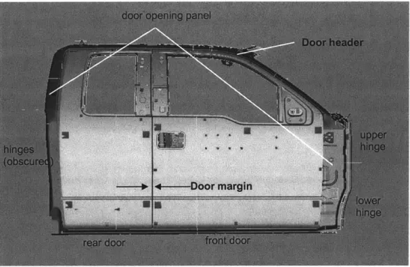
The closure system of concern for this thesis is that of vehicle doors. A brief description of each of the primary components is necessary, many of which are depicted in Figure 2-1, which shows a door closure system for a Magna-duty truck.
Figure 2-1: Truck Door Closure System
This particular vehicle has two doors (front and rear) each supported by two hinges (upper and lower). Since this design contains no pillar between the doors, the rear door's hinges are located
towards the rear so that the door opens backward - opposite that of the front door. All four hinges connect the doors with the DOP or door opening panel which surrounds and frames the doors. The role played by the door header, which is the portion of the door above the window, is often critical to achieving customer satisfaction. Additionally, the presence of several layers of sealing (or 'weather stripping') can be noted along the door or DOP. Finally, the system's striker and latch mechanism work to keep the door closed. The body's strikers (not shown) are metal bars that engage with the door latches and catch to hold fast. In this system, the rear DOP
contains two strikers that match to latches within the rear door, while the rear section of the front door contains a single latch placed to engage with a striker installed in the rear door. Because of this, the rear door must always be closed first.
The selection of each system component as well as its relative position and orientation is informed by the strategy that has been set for how the door is to be hung. This is known as a hang strategy. During the development of a program's final design, this strategy may evolve in an iterative manner as engineers work to satisfy design requirements. For this reason, a thorough understanding of the interrelatedness of each component is essential. Certain hang strategies such as the use of a NAB pin hinge with rocker tool can be expected to yield results that will be favorable to one or more customer attribute, as will be explored in future chapters.
Door System Attributes
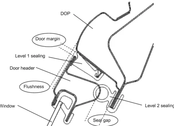
Generally, a set of attributes for this system can be considered to include those listed below. Figure 2-2 depicts a cross-section of a closed Magna vehicle door looking in the area of the header and the DOP with two levels of sealing. As many of the salient customer features involve metrics associated with cross-sections such as these, the term 'vehicle section' is employed to refer to them. The figure below shows how some of the critical customer attributes are defined:
DOP
Door margin
Level 1 sealing
Door header
Window Level 2 sealing
Figure 2-2: Cross-section of Closed Door
* Door Closing Effort (not shown): This represents the amount of force, and the duration over which that force must be applied, in order to completely close the door. This attribute is best understood as being the customer's overall satisfaction with the action of closing his/her door. If door closing effort is too high the customer experiences strain and frustration with repeated closings of the door and may cause the door latch to only partially engage the respective striker. Conversely, if door closing effort is too low, the customer will find himself 'slamming' the door unnecessarily hard. In extreme
conditions, the door may 'close itself if the vehicle is parked at even a slight incline. The feel of the door as it is closed has been found to convey product quality cues to the vehicle owner.
* Door Margin: Door margin is understood to mean the gap which surrounds each door and which is measured either from door edge to DOP edge or door edge to door edge. Achieving acceptable door margin means ensuring that this gap is consistent and of
minimal size. Although door margin should be controlled around the entire door, the area of greatest concern is the space above the header since this is the margin that will be most obvious to potential vehicle owners.
" Door Flushness: Door flushness refers to the outboard alignment of door to DOP (or door to door) and can be qualitatively assessed by running your hand over the door margin and feeling for a change in the in/out position. Generally, doors should be set perfectly flush to the other framing components.
" Door Closing Sound (not shown): Many customers have shown a preference for particular sounds associated with the close of a car door. Although some of these preferences are obvious (e.g. lack of rattles or squeaks), others are more complex and involve the door sounding 'solid' upon closing.
" Door Water Leaks (shown as seal gap): This customer requirement consists of the door subsystem not allowing water to flow inside the vehicle once the windows have been closed, and depends heavily on the ability of the door to create a robust seal with the DOP and other door.
" Door Wind Noise (shown as seal gap): Door wind noise is an attribute which quantifies the loudness (in sones) of air egress while driving. As discussed in the previous chapter, this is considered a high priority customer attribute. The ability of the system to achieve acceptably low levels of noise is directly related to its ability to provide adequate sealing. The seal must fill the distance set by the seal gap, despite the various conditions the system will be subjected to, including aging, changing temperatures, and extreme
pressure differentials between the inside and outside of the cabin. These conditions tend to affect the door's outboard position with respect to the DOP, often leading to door deflection which is sufficiently high to allow the egress of air. Figure 2-3 shows typical pressures seen by the closure system.
Figure 2-3: Surface Pressures Applied to Magna-duty Truck Closure System
Wind noise and its Relationship to Seal Gap
In practice, designing for a customer attribute such as wind noise is exceedingly difficult. One reason for this is the large number of external and environmental factors that influence the behavior of the sealing system. However, one method for increasing the robustness of the design to these effects involves decreasing the size of the seal gap relative to the sealing system. In this way, even as door undergoes outward deflection, it will prove less likely to allow the egress of air through the gap. This simplifying design method of minimizing seal gap is currently applied at Magna. Although this method does not suddenly give us an easy design parameter (the minimization of seal gap is a difficult requirement), it does provide a method of limiting our design work to geometric relationships and allows us to be less concerned with the external factors. Studies have been performed assessing the relationship between a vehicle's seal gap and
the door deflection (shown in Figure 2-4). This work has demonstrated the tendency of vehicles with smaller gaps to experience decreased door deflection when subjected to real world
conditions. The figure below shows a Magna truck's door deflection at a simulated 100 mph highway speed. Trucks with smaller initial gap sizes demonstrated less deflection and less wind noise as a result. Because of the reasonableness and widespread practice of substituting seal gap as a proxy for wind noise, this thesis will consider seal gap size as the customer attribute of interest.
Deflection vs. Seal Gaps
C 0 0 4) 0 0 0 6.0 5.0 4.0 X -3.0 E2 2.0 1.0 0.0 12.0 y 0 1726x2 - 4.5636x+ 31.272 R 2 = 0.9829 13.0 14.0 15.0 16.0 Seal Gaps (mm) 17.0 18.0 19.0
Figure 2-4: Higher Door Deflection for Larger Initial Seal Gaps
In line with the results shown above, Magna CSI's have found that doors may rotate outwards (as a semi-rigid body, within minimal flex) when these high speed pressure loads are applied.
Having provided background on Magna's door closure systems, it now remains for us to consider the nature of the complexity found in these systems before we turn our attention to the application of system tools.
CHAPTER THREE: AN INTRODUCTION TO SYSTEMS LEVEL THINKING
Mapping of Complex Systems - Motivation for a Tool-Driven
Approach
It is obvious to those within the automotive industry that any given vehicle represents a complex assemblage of designed components. Less obvious is the level of complexity required by the engineering tools applied to understand and improve such a system. Such tools have
traditionally been seen as a means by which to improve the designer's insight into how he/she might modify an existing design - leaving the ultimate decision making authority to the
discretion of the most knowledgeable engineer. Tools, then, play a critical but subordinate role to intuition; informing but not mandating a given approach. As system complexity continues to increase, intuition and experience must play an increasingly smaller role in the final design of vehicles. Instead, data driven tools capable of solving simultaneous deliverables while satisfying a vast number of constraints, must become more prevalent.
For our purposes, the definition of a complex system [from Magee and de Weck] will be taken as: a system with numerous components and interconnections, interactions or interdependencies that are difficult to describe, understand, predict, manage, design, and/or change There exists a wide variety of such systems, which can be described by features of their behavior such as the number and diversity of elements, or their interconnectivity. Figure 3-1 represents five of these categories.
Figure 3-1: Features of Complex Systems
The system may be complicated by the level of intricacy associated with each of the
subcomponents which comprise it. Similarly, the number of components involved within a defined system may serve to add a level of complexity, as might the range of design of each of
the included pieces - and the differences they bear with respect to one another. Component interconnectivity can also vary widely depending on the construction and purpose of the system and may diminish the benefit of segregating and analyzing sections of this system independently. Finally, every system is subject to structural constraints - and must be constructed in such a way as to ensure each element is properly oriented with respect to the remaining elements. As a system's complexity increases along these (and other) dimensions, it becomes increasingly difficult for the human mind to develop intuition concerning the patterns of cause and effect flowing from that system.
Three Categories of Complexity
As Magna is in the business of designing and assembling systems, it is useful to consider the extent to which human intuition - even that of trained technical employees - is capable of managing complexity. As a simplified first attempt, engineered systems can be thought of as
falling into one of three categories: first order, second order, or irreducible.
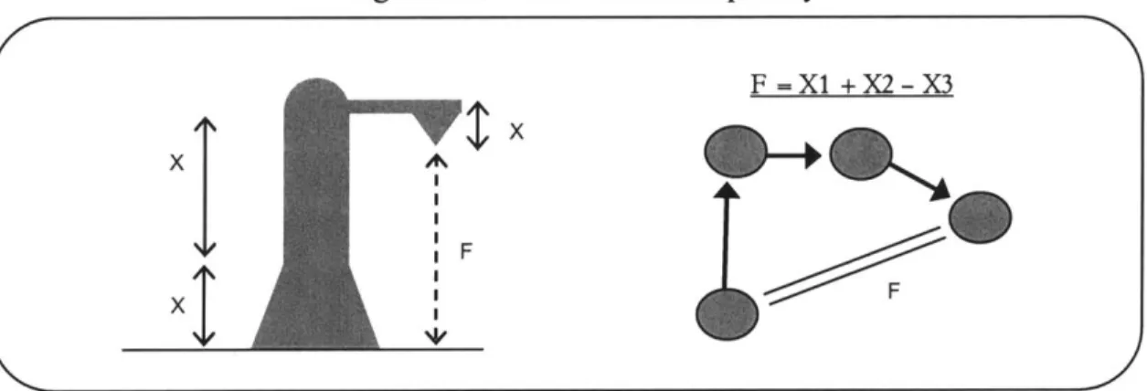
First order systems refer to those that can be regularly satisfied by modification of a single factor at a time. These are the simplest of the three, often requiring a minimal level of insight into the behavior of the components, and are the most common of the systems found in daily life. Such a
system can be seen in an assembly where designed components combine to control a single overriding feature as seen in Figure 3-2. Examples of real first order systems include an office chair whose height adjustment handle independently controls the position of the user along one dimension, or a heavily secured front door which, in order to be opened, must undergo a series of
sequential modifications, including the sliding of a chain lock, the spinning of a deadbolt, and the twisting of a door handle.
Figure 3-2: First Order Complexity
F =X1 +X2- X3
xt
Second order systems are defined as those which attempt to satisfy multiple (often conflicting) attributes which fundamentally relying on the arrangement of the same set of components. For these systems significantly greater knowledge must be obtained before any modifications or improvements can be achieved. This is due to the potential of disrupting system attributes unintentionally or (even worse) unknowingly. In the case where a component may be serving 'double-duty' for two or more deliverables, but is not faced with an intrinsic conflict, optimal solutions may be found to satisfy the desired system state. However, when conflicts do exist, the need for tradeoffs should be anticipated and the relative prioritization of system attributes must be performed. Due to the multiple simultaneous objectives of these systems, and the difficulty
faced by the designer who is trying to 'keep his eye on the ball', it doesn't take a large number of interrelated elements for traditional intuitive approaches to quickly bog down. Figure 3-3 shows a representation of a second order system. Examples of these include the band of a watch, which must be loose enough for comfort, but tight enough to hold fast, or some aspects of an
automobile's internal combustion engine which must provide sufficiently high power for driving, while minimizing consumption of fuel and noise (among others).
Figure 3-3: Second Order Complexity
X1 X2 X3 X4 X5 F F1 WWMM F2 MMMM F F3 MMMM F4F
F4
S
The third category of system includes those with a high level of constraint across elements due to imposed standardization of common component designs. This category, known as irreducible, is a relational design with standardized constraints and occurs when the modification of a system's critical components is restricted due to the impact such changes would have on other components which share the same standard, but are otherwise indirectly related. An example helps to clarify this system. Consider the electrical cord of any household appliance. As the homeowner goes to plug this appliance in, he finds that the cord's electrical prongs don't quite mate with the wall
outlet. This misalignment can be remedied immediately by deformation of the prongs to match the slot spacing of the outlet - allowing the system to achieve its function. However, should the fault lie with the outlet then the corrective action just taken will prevent the appliance from matching with the remaining wall outlets in the house. Before component modification occurs, it must first be determined which design standard has not been achieved. In general, however, it is not possible to alter the design for a single product (so designated as irreducible) without
likewise altering the related design of an array of other products.
Ultimately, it could be argued that every component and subsystem that ever has or will come into contact with one another are all constituents of the same encompassing system. However, the creation of this third category allows systems to be considered independently while retaining the interdependence they share based on a common, standardized design. For Magna, these standards govern several of the design activities. For example, one requirement established by standardization is that every truck door be produced identically in order to match with any one of the identically produced truck bodies. Although in reality these doors will never be part of the same system, they influence one another indirectly through the establishment of common
standards and management decisions such as whether or not to employ functional build strategies. Similarly, as a standard door hinge emerges for use across multiple programs, the freedom of any system or platform to modify its components is diminished. This category of system, which is governed by cross-program constraints, is depicted in Figure 3-4.
Figure 3-4: System w/ Standardizing Constraints
System 2 common standard 'h- -..---
KX
* I common standard System 1 0 0 0 0w
01010 0 .. o o0
o ...---The Use of Systems Tools for Optimal Design
Recognizing and categorizing systems as being of first order, second order, or irreducible complexity should not be seen as mere exercise but as a means to match the need with the tools appropriate to solve it. Even in cases where a system, or collection of systems, cannot be cleanly defined using this methodology, it remains critical that engineers responsible for design
strategies begin with these concepts in mind. In so doing, it then becomes possible to identify the gaps between what the current state of engineering tools can achieve (these tools include among them the human mind and its capacity to visualize and understand complexity) and what they need to achieve in order to continue organizational improvement.
Practically speaking, once a system has been categorized, it is then necessary to determine how tools may be developed or applied to take the burden of excessive complexity off of the
shoulders of the designers. Although Magna has made use of a variety of toolsets in order to improve vehicle quality, it remains to be seen whether these tools will remain sufficient in an increasingly competitive marketplace with an increasingly complex product. Unfortunately, tools currently in place are insufficient to properly design systems requiring second order complexity or to thoroughly inform the strategies governing designs which cross a variety of programs - as is the case with Magna's current push for standardization.
Instead, tools at use at Magna generally show themselves to be excellent for optimizing simple systems or for breaking complex systems down and delivering sequential analysis. Without the use of sufficiently capable tools, design solutions that may improve the product line will remain hidden. Figure 3-5 demonstrates these 'undiscovered solutions' which may provide optimal
achievement of design requirements, but which cannot be located by current tools. Acceptable designs are those which occur at the intersection of established design concepts which are known to exist, and those designs which fulfill all necessary requirements. As shown in Figure 3-5,
Magna designers often begin the process with solutions that do not fulfill the full range of system requirements. The onus is then on them to iterate until the resulting design concept does satisfy the requirements. Although current methods often prove adequate for determining a 'good'
design, they may not be capable of discovering every solution, and therefore potentially leave the optimal solution undiscovered.
Figure 3-5: Failure of Tools to Uncover Solutions
Desian Space Design Regj4r&ment o6nce Pitesign Targe Region Undiscovered - - - - -Solutions o Unworkable Designs
This next chapter will consider the use of system tools in place at Magna. These tools are currently employed to iterate the best reasonable design and have different uses within the organization. By presenting a brief introduction to these tools, we will then be able to move to recommendations for the improved use of system tools.
CHAPTER FOUR: USE OF SYSTEM TOOLS AT MAGNA
A senior leader at Magna is known for having said: "If you give engineers good tools they will use them." The truth of this statement can be debated, but it is at least evident that engineers who have insufficient tools to aid them in system design will produce designs that are lacking. As might be expected of a company as large and organizationally complex as Magna a large number of tools go underused (or unused) due to lack of awareness or concern. As this project is concerned with the development and recommendation of improved tools for system-level vehicle design, it is reasonable to first assess which tools have been historically used and are of great familiarity. The primary goal of this chapter will be to demonstrate the inadequacy of current tools to delivery engineered systems of the highest customer quality. In the following chapters, our thoughts will be turned to a tool that has more recently been developed but has not yet been used to Magna's full advantage.
The Current Use of Limited System Tools
Engineers at Magna have made proficient use of a number of tools as means of diagnosing and solving issues associated with systems. Included among these are computer aided tools such as
CAD (computer aided design), FEA (finite element analysis), CAM (computer aided
manufacturing) and CAE (computer aided engineering) as well as physical modeling tools such as Rapid Prototyping and Royalite models. However, in the gaps that exist between these tools, Magna engineers have demonstrated the tendency to patch their work using significantly less
sophisticated tools such as the worksheets used to keep track of iterations on vehicle section requirements.
Each of these traditional tools has unique limitations, which we will not fully explore here. However, it is worth noting that each of these tools is generally employed in such a way that local incremental improvements are sought without regard to the impact of the assembly as a whole. The use of CAD and CAE tools serve as an example of these tools' limited ability to deal with second order complexity.
An engineer such as CSI who is responsible for ensuring achievement of a program's vehicle sections, is constantly in need of means by which to measure the current expected value, and to make alterations. By relying on CAD models of a targeted vehicle, it is possible for a CSI to quickly determine the numeric value of a particular assembled dimension. For instance, he can use the file's 3D data to 'measure' the seal gap that the model shows exists between the virtual
door and the virtual truck body. In this way, tracking any single critical characteristic is relatively easy. However, should this value not be appropriately centered within the expected
dimensional range some redesign of the underlying components or else a new assembly strategy becomes necessary. The CAD model - which merely represents the parts as currently designed
-offers little assistance on how best to go about this design work without negatively affecting related attributes. Thus the engineer may be left to a sort of frenzied trial-and-error approach in
order to meet his section requirements by the deadline.
The CAE tools used at Magna can generally be considered robust but less than perfectly exact when used in the analysis of a system's response to manufacturing and environmental variation. Often CAE is used to morph the existing surrogate design into the new, desired shape. However, these tools are far from perfect and have been known to yield results discrepant from the "real
life" behavior of the system. One example of this discrepancy between CAE results and actual behavior can be found in a recent CAE study contrasting hang strategies employed in Magna
doors and in Vega (another disguised automaker) doors for various vehicle models. The CAE model predicted superior performance of the Magna doors for wind noise and other categories. However, the Vega door was found to better achieve the targeted performance metrics, based on
a side by side comparison of assembled vehicles. This deficiency is not yet entirely understood, but is due in part to the software's inability to correctly model the simultaneous inputs expected
from a real environment. Similarly the tool is not adept at capturing the impact of system parameters on the various vehicle subsystems which may in turn influence any given attribute. Thus we see related behavior between the CAE and CAD systems, both of which begin to break down as system interdepencies go unregistered.
The widespread use of non-computational tools should also be briefly considered. These include checklists, worksheets and paper-based matrices which may find use in lieu of more complicated
software packages and suggests some level of engineering dissatisfaction with the available collection of tools. One example of this is the PD CSI's target matrix which is used to manually record the value of an attribute (e.g. seal gap) as it changes. These changes in seal gap come about as design engineers are asked to modify their designs in order to meet the section requirement. As progress towards this section requirement is continually made, the matrix is updated. Similarly, the use of a 'parameter sheet' by CSI's helps to generate section targets, part tolerances and anticipated stack-ups and is considered to be good for team collaboration. Within manufacturing groups, a prioritization matrix may be employed to rank the 'relative importance' of conflicting attributes. This is then used to make ultimate decisions about which attribute
should be 'favored' if the need for equipment adjustment arises. This use by Magna engineers of primitive heuristics to make decisions affecting customer satisfaction represents a break down in the availability of solid, effective tools. The need for better tools is obvious to many and the automaker has begun to take steps to improve their situation.
Second Order Systems Tools in Use at Magna - DVA
In addition to the tools already discussed, there is at least one other which has taken root within the organization and which offers significant advantage to the engineers and teams that are proficient in its use. This tool is known as Dimensional Variation Analysis (DVA). It is worth considering the current use of DVA in order to understand the gaps that remain today in the use of system-level tools.
Introduction to Dimensional Variation Analysis (DVA)
Dimensional variation analysis has been in use for decades at Magna, but remains poorly understand and underused. Using geometric CAD data for vehicle components, the DVA group is able to perform Monte Carlo analysis by varying the position of each component within its prescribed tolerance in order to view the resulting geometries of the final system. This is considered the primary function of DVA analysis and is typically performed by request from program manufacturing groups as problems are encountered related to product launch. Less often, DVA verification may be requested midway through the design process to ensure that vehicle section deliverables are achievable. The DVA group responsible for these analyses is
small, independent, and found in Magna locations throughout the world (including England, Germany, Brazil and Australia.
Current Use of DVA
Today, DVA is considered a post-mortem design tool. Design will alter its model and then apply DVA to see if it works. Because of this, DVA influences design but does not inform it. Often the insight drawn from this analysis comes too late to be of much help - by this point the strategies are too far developed to be rethought. Rarely, the techniques of DVA might be requested very early in the design phase, before CAD data has replaced the 'cocktail napkin' sketches. Such up front collaboration allows those knowledgeable about the impact of component geometry to have a voice in the choice of strategy. In fact this is exactly the way members of the DVA group prefer the tool to be used - in order to save work and minimize missteps from Design. As one DVA employee told me, "I predicted this problem a year ago but no one listened". The reason for the limited use of this group and its set of tools stems in part from a lack of familiarity with the capabilities available through their use. Additionally, a general preference among some programs to decide their own strategies coupled with the possible backlog of work; prevent the design group from seeking out additional (possibly time-consuming) feedback until absolutely necessary.
DVA Outputs and Results
When properly used, DVA is capable of producing a variety of useful results. These include calculation of expected means and deviations of geometric customer attributes (e.g. seal gap dimensions) as well as calculation of necessary component and assembly tolerance based on the desirable mean and range for the final customer attribute (in effect working backwards). In addition DVA is capable of identifying major contributors of final assembly error (deviation from mean) in order to help focus attention on the appropriate sources. This is done through a high-low-median analysis in which transfer functions are generated and supplied to design teams. The rigidity and stability of the system are also computed through the use of the software.
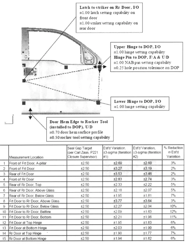
Finally, the output from a run can be used to generate transfer functions for Six Sigma black belts. For an example of a DVA run on the Magna-duty truck closures, see Figure 4-1 below.
Latch to striker o
*1.00 latch setting
front door
±1.00 s tnker setti
rear door
.bibb1B~hbilhli .bsi l~ lllli~ i w la sa hllliia a... a... Au .i a ihliUiblis uhbdlllu liil uis'uanalilhaelalbhlishbi blbbio Ilell lm a
n Rr Door, 11O
capability on
g capability on
Lower Hinge to DOP, 1/0 =1.00 huige setting capability
"I
Door Hem Edge to Rocker Tool (installed to DOP), U/D=0.70 door hem surface profile ±0.50 rocker tool setting capability
Seal Gap Target Est'd Variation, Est'd Variation, % Reduction
(per Carl Zaas, P221 3-sigma (teration 3-sigma (Iteration in Est'd
Measurement Location Closure Supervisor) #1) #2) Variation
I Front of Frt Door, A-pillar t2.50 ±2.69 ±2.60 3%
2 Front of Frt Door ±2.50 ±3.27 ±3.19 2%
3 Rear of Frt Door ±2.50 ±3.53 ±3.46 2%
4 Front of Rr Door 2.50 ±2.83 ±2.74 3%
5 Rear of Rr Door, Top ±2.50 ±2.33 ±2.22 5%
6 Rear of Rr Door, Above Glass ±2.50 ±2.18 ±2.07 5%
7 Rear of Rr Door, Below Glass ±2.50 ±1.95 ±1.81 7% 8 Frt Door to Rr Door, Above Glass ±2.50 ±3.77 ±3.64 3% 9 Frt Door to Rr Door, Below Glass ±2.50 ±2.27 ±2.04 10%
10 Frt Door to Rr Door, Beltline ±2.50 ±2.09 ±1.83 12%
11 Frt Door to Rr Door, Bottom ±2.50 ±2.21 ±1.96 11%
12 Frt Door at Top Hinge ±2.50 ±1.95 ±1.83 6%
13 Frt Door at Bottom Hinge ±2.50 ±2.03 ±1.90 6%
14 Rr Door at Top Hinge ±2.50 ±1.90 ±1.77 7%
15 Rr Door at Bottom Hinge ±2.50 ±1.94 ±1.82 6%
Figure 4-1: Magna-duty truck DVA analysis for seal gap
Figure 4-1 presents a CAD file for a typical Magna-duty truck and considers the critical points of connection. In order to ensure that the seal gap at each of the measurement locations (for
Upper Hinge to DOP, 10
=1.00 hinge setting capability Hinge Pin to DOP, F/A & U/D
=1.00 NAB pm setTIng capability
instance #1 Front of Front Door at A Pillar) falls within an allowed tolerance, the deviation introduced by subcomponents and subassemblies is combined. This yields an estimated variation within which 3 sigma of assembled trucks are expected to fall. However, some simplifications are present in this analysis which may lead to larger errors than predicted by the analysis. One example is the conventional treatment of a door as a rigid part, or as two rigid parts (one above and below the beltline). In reality, flex associated with the manufacture and assembly of this door may introduce additional variation.
Technical Objections to DVA
Although DVA is a powerful tool for systems-level analysis, there exist some barriers to its optimal use. One of the current issues involves the occasional use of incomplete CAD models to perform DVA analysis. Although the development of CAD data does not fall under the DVA's
group sphere of control, they ultimately own the output of their analysis and are held responsible for inconsistencies. Similarly, for DVA runs performed for manufacturing groups, data collected from the shop floor is routinely found to be sufficient but not entirely complete. Minor details concerning the manufacture may be lacking including the order of assembly or the presence of minor deviations due to manufacturing. Because of these and other limitations, even those DVA runs that are taken to completion may not lead to beneficial program changes.
DVA does not readily give engineers a method to directly influence design, but instead allows them to check the current design for predicted discrepancies. One reason that its use cannot ensure a properly designed vehicle is that it is not yet capable of analyzing the effect of fixturing and tooling on the manufacture of the final parts, nor is it able to consider the assembly sequence or the necessary manufacturing details (such as the slight taper on a thermoformed pin necessary to remove it from a mold). These limitations are technical in nature but could be improved upon by clearer lines of communication between manufacturing groups and DVA. In many cases the DVA groups are expected to work only from the design drawings (or models) for components instead of also gathering data concerning the manufacturing processes. As a result the analyses performed by the DVA group will blindly use the 'print' tolerances range as they are received from the design group - although rarely do these ranges mirror reality.
Although the full Monte Carlo simulation dynamically varies every contributing sub-component in order to obtain a true distribution of a system's final state - the HLM (high-low-median) Monte Carlo does not. Instead, this simulation - which is responsible for generating the "contribution effect" of components for engineers - applies a linear approximation and varies only a single component at a time. This means that some interaction effects may not be captured and so may result in some overlooked system relationships. Apparently no problems have yet been reported due to this simulation limitation. Presumably any interaction effect not captured in the HLM run will have been noted in an earlier full Monte Carlo. Although none of these
technical limitations constitute a reason to abandon the use of DVA, they do help to explain the lack of support among engineers.
Figure 4-2 gives an example of the contribution spreadsheet as provided to engineering. This sheet is one of the more useful outputs of the DVA process and allows design engineers to understand the quantitative sensitivity of a given attribute to the design of the underlying system. By making alterations to the design strategy, the sensitivities associated with each component change. The use of this contribution spreadsheet enables the design engineer to work backwards, by asking how changes to the sensitivities might improve the desired outcome - and then how design strategies can be modified to accommodate this. Similarly the tolerance for each feature of each critical component can be varied to reflect potential manufacturing or design
improvements. Ultimately, the goal of the engineer is to ensure that the appropriate customer characteristic is met within a three sigma range of assembly. Estimated Variation (shown in the figure) is found by applying the RSS method to the computed Effective Tolerances above, and allows iteration of values until the target tolerance is achieved.
Orig Tol Rev Tol Eff. Tol Eff. Tol (HLM) FRT RH -02 -RH FRT 2.428 0.70 0.70 1.699 1.699 28.48 FRT RH - 01 - RH FRT 2.376 0.70 0.70 1.663 1.663 27.28 5420124.02 MS, x 2.428 0.42 0.42 1.020 1.020 10.25 5420124.01 MS, x 2.376 0.42 0.42 0.998 0.998 9.82 FRT RH - 10b -MP, 1.000 0.70 0.70 0.700 0.700 4.83 RH -04a -MS, 0.783 0.70 0.70 0.548 0.548 2.96 FRT RH - 03a - MS, 0.783 0.70 0.70 0.548 0.767 2.96 outer -18b -MP 1.000 0.50 0.50 0.500 0.500 2.47 5420124.01 MS, y 1.037 0.42 0.42 0.436 0.436 1.87 5420124.01 MS, z 0.721 0.60 0.60 0.433 0.433 1.85 5420124.02 MS, y 0.946 0.42 0.42 0.397 0.397 1.56
Tol - Hng NAB Pin, Y 0.770 0.42 0.42 0.323 0.323 1.03
Estimated Variation 3.109 3.155 TARGET TOLERANCE 2.00
Figure 4-2: Contribution Effects
Conflicting Perceptions on the use of DVA
Those Magna design and manufacturing personnel familiar with DVA appear to be of two minds concerning its use - there are those with high expectations for its capability, and there are those who have been disappointed by its use. These diatomically opposing responses can be attributed to the perceived role of dimensional variation analysis - which is to provide accurate and final quantitative results. Due to the limitations cited above, the results of any DVA analysis must be received tentatively and with regard to the process used to arrive at them. For this reason, it is the method of approach offered by the DVA, and not its numeric outputs, that should be
considered its primary advantage. This third perspective of the tool must still require analyses to be performed correctly - but should be even more interested in the insights that can be captured by its application.
Recommendations for use of DVA
Although a study of the current use of DVA uncovers a number of key technical
recommendations for its improved use, the most critical advice applies to the culture surrounding
(+1-) (+/-) ±3 Sigma (+1-)
and communicating with the DVA analysts. The method of approach practiced by the DVA analysts and engineers, and their understanding of the intricacies of system design, were
fundamentally sharper than those of their counterparts within the Magna organization. This is a credit to the years of practice they have had gathering data from each and every involved
functional group within Magna and the time spent determining the systemic effect of changes to components. This resulted in the ability of the DVA analyst to 'hold his own' in several
meetings I was privy to, where he debated design intent with program engineers. Despite their lack of in-depth knowledge concerning the various nuances of each program's design, the DVA analyst's ability to relate final system attributes to the condition of components or features was uncanny. By contrast, the design engineers often found it difficult to understand the many inputs to a system design since they did not have the necessary information from other groups. The
first and overarching recommendation then is that Magna work to develop similar thinking within its own engineers while making greater use of those within the DVA group. This means not simply issuing more requests for analyses, but rather making members of this group active partners earlier in the design process. Moreover, it is recommended that design engineers and
CSI's spend time performing DVA analyses on their own sections - and working to gather information and compare notes with other functions whose components prove critical to the delivery of customer attributes. The thinking that has been cultivated by the use of DVA within Magna will prove useful as the organization practices the use of DFC (Datum Flow Chain) techniques which are particularly well equipped to provide the necessary language and methodology for complex systems analyses.
From a technical perspective, several recommendations should be mentioned.
1. First, a typical analysis may only trace the relationships between a final customer attribute and a set of sub-assemblies. Instead, additional insight could be gained by following these relationships the entire way back to the constituent sub-components. This would also allow more extensive communication to design engineers involved in the earliest stages for the most fundamental components.