Design of An Assist Device for Automated Rolling and
Repositioning of Bedridden Patients
by
Arin Basmajian
B.S., Mechanical Engineering
Massachusetts Institute of Technology, 2000
Submitted to the Department of Mechanical Engineering
in Partial Fulfillment of the Requirements for the Degree of
Master of Science in Mechanical Engineering
at the
Massachusetts Institute of Technology
June 2002
BARKER
OF TECHNOLOGYOCT 2 5 2002
LIBRARIES
@ Massachusetts Institute of Technology, 2002. All Rights Reserved.
Author ...
Depaarennte
Certified by ...
0 Mechanical Engineering
May 6, 2002
Ilaruhiko H. Asada
Ford Professor Of Mechanical Engineering
Thesis Supervisor
Certified by ...
Emesto
E. Blanco
Adjunct Professor of Mechanical Engineering
Thesis Supervisor
Design of An Assist Device for
Automated Rolling and Repositioning of Bedridden Patients
by
Arin Basmajian
Submitted to the Department of
Mechanical Engineering
on May 6, 2002
in partial fulfillment of the requirements for the degree of
Master of Science in Mechanical Engineering
A novel design for rolling and repositioning a bedridden patient is presented. A pair of
actu-ated rollers are attached to both sides of the bedsheet in order to lift and manipulate the
patient body. The patient is gently supported on a hammock-like active bedsheet, creating
vir-tually no shear forces on the patient body. Therefore, the patient can safely and easily be
maneuvered with minimal physical assistance by the caregiver. This prevents development of
painful bedsores and of pneumonia. In this thesis, functional requirements and design issues
are addressed, followed by basic design concept, mechanism, and control strategy. A simple
kinematic model is built to create trajectories for generation of desired body motion. A
proto-type is built and initial experiments demonstrate that a human body is rolled and manipulated
by the assist device, providing proof of concept. Extended functionalities including
bed-to-chair and bed-to-bed transfers, are described at the end.
Thesis Supervisor: Haruhiko H. Asada
Title: Ford Professor of Mechanical Engineering
Thesis Supervisor: Ernesto E. Blanco
Acknowledgements
I would like to thank my grandfather who told me that I had to follow my
dream. I wish he could be here to see it come true. I would like to thank my parents and brother, who contributed greatly to my being here today; without their unconditional love -- even during times when I was driving them crazy
-- I could not have made it through. Thanks also to my aunt, Houry, for her
endless support and patience.
A warm thank you goes to both Professor Harry Asada and Professor Ernesto
Blanco for giving me such an opportunity to work on a truly exciting project and especially for teaching and guiding me along the way. I would also like to thank Professor Sarma for taking time out and being a mentor to me during this eventful year.
This thesis would not have been written without the support of my room-mates, Kavita and Janelle. You were my strength when I ran out of my own. Thank you.
A big thank you to all my friends, you know who you are, who reminded me
of life beyond work, who believed in me, and who stood by the various deci-sions I made this year, yes, Jomaldo and Dinesh, that goes to you in particular.
Thanks to Petros, for his help, both in the formatting of this thesis and other-wise. I would be very ungrateful if I did not thank my labmates in the d'Arbe-loff Lab, in particular, KyuJin -- for his intense dedication to research and for heading the camera crew -- Binayak, Eric, Mikii, Phil and everyone else for being labmates, friends, advisors, critics. Oh, and for tolerating my out-of-tune singing!
Thanks to the machinists in the Central Machine Shop, and Steve in the Pap-palardo Lab, for instructing me not just on machining and the art of painting but for all their work and support too. I truly appreciate it.
I may have typed this thesis on my own but getting here was a team effort.
Table of Contents
CHAPTER 3
Introduction and Background ...
11
Functional Requirements and Design Concept ... 15
(1) Functional Requirements ... (2) Design Concept ... (3) Operation... Airborne Rolling... Pivotal Rolling ... Horizontal Translation ... Changing Bedsheets ...
System Modeling and Analysis ...
25
Modeling the Problem ... Determining Location of Patient...
CHAPTER 1
CHAPTER 2
... .15 ... 16 ... 19 ... 1. 20 ... 21 ... 21 ... 22 ... 25 ... 29 . .. .. .. .. . ... ... .. ... ... ... ... . .. .. .. .. . ... . . . ...... ... .... .... ...CHAPTER 4
Motion Planning ...
33
Trajectory Generation ... Rolling ... Bed-Bed/Chair Transfer... Control ofActuators... ... 33 .... 33 .... 36 .... 38CHAPTER 5
CHAPTER 6
Implementation of First Prototype ...
.. . . . . 41
(1) Mechanical Design and Electronics ... 41
Selection of Materials and Determination of Design... 43
Choosing the drive shaft ... 43
Electronics ... 47
(2) Verification of Concept... 50
(3) Verification of System Model... 55
System Verification...56
Patient Translation...59
(4) Control Software Implementation ... 60
Control Code for Rolling and Transfer ... 63
Conclusion and Future Work ...
65
Discussion ... Future W ork... Future Work regarding Design and Structure of Device ... Future Work with respect to Reinforcing Bedsheets... Future Work regarding Electrical Circuitry ... .. 65 .. 66 ... 66 ... 68 ... 69
APPENDIX A
References...71
Historical Record of Approaches ...
73
Chronology of Designs ... Honeycomb M otion... .. 73
APPENDIX B
APPENDIX C
APPENDIX D
Tilt and belt... 76
Tilt and tilt... 78
Changing Bedsheets ... 81
Axial Positioning... 82
Assembly Drawings ...
85
Part Drawings and Listing... 89
Part Info...89
Hardware, Software and Common Operation Tips ....
123
Tips on Using the Hardware and Software of Machine...123
To Improve Performance of Gearboxes... 123
Hardware Considerations ... 125
CHAPTER 1
Introduction and
Background
As people get older, their mobility becomes impaired and they need assistance performing everyday tasks. In many instances, they are bedridden and may develop, in particular, bedsores and pneumonia. Bedsores are formed due to the continuous application of pressure on a person's body part. There-fore, redistribution of pressure applied to the body may be taken as a preven-tive measure. Also, a patient's own motion helps to reestablish blood flow and so prevents cell death.
Repositioning the patient is not only advantageous for prevention of bedsores but also for preventing pneumonia. Pneumonia is an infection of one or both lungs in which fluid and damaged lung cells fill the air spaces in the lungs, making it difficult to breathe. Viral pneumonia, generally milder than the bacterial form, is the result of lower respiratory infection and has been the cause of more than 90% of deaths for individuals over 65 [1]. Stagnant mucus in the lower airways is a medium for bacterial growth, should pathogens reach
Introduction and Background
the lower airways. Routine turning and positioning assists in mobilization of secretions. Patients having breathing difficulties may find relief by being turned slightly on their side [3]. Caregivers move patients manually, a highly labor-intensive task. According to a survey by Garg et al [6], a nursing assis-tant performs over 50 such tasks per eight-hour shift. This results in alarm-ingly high numbers of back injuries that cost $24 billion each year [8].
In this thesis, a new methodology will be developed to assist patients in turning and repositioning. Both patients and nursing personnel will benefit from the proposed design. Bedsheets - with the aid of the marionette device
presented in this paper - may be used to roll patients. Turning helps prevent
bedsores. The patient is turned with almost no physical exertion or risk of injury. Only one caregiver will be able to turn the patient easily. By tilting a sheet laterally, rolling a patient becomes an easy task. It not only causes a change in the person's position, thereby altering the pressure but also stimu-lates blood flow. The patient may be moved to either edge of the bed. Bed-sheets can easily be changed and nursing personnel no longer need to pull patients on the bed so reducing their own backache.
There are a few commercially available beds that fulfill some require-ments of patient and nursing personnel. Hill-Rom [4] and Kinetic Concepts
Inc. (KCI) [5] are some of the companies that make hospital beds. Beds range
from manually-operated to electrical ones, some even equipped with fluidized therapy units that provide pressure relief. However, their cost is exceedingly high and the beds are big and bulky. The device designed has the main advan-tage of having almost no set-up time. The hoists that are currently on the mar-ket, such as the Sara-Lift', often remain unused in hospitals and nursing
homes. Nursing personnel complain that the setup time is too long. Caregivers do not wish to go through the trouble of setting up the equipment, which can sometimes take up to 20 minutes when the actual task would take a fraction of that time. Furthermore, patients feel unsafe being completely airborne when using these lifts.
This thesis explores a new approach and presents a device that uses bedsheets to maneuver the human body. Using the bedsheet is beneficial to the patient because it does not produce large stress concentrations across the body, and it reduces the harmful shear forces. In addition, it is flexible so it adheres to the shape of the person. The remainder of this thesis is organized as follows. Chapter 2 deals with the methodology of the approach and the actual design. Chapter 3 presents a kinematic model. Chapter 4 introduces the analy-sis and control of the machine. Chapter 5 illustrates its implementation. Chap-ter 6 suggests extended functionalities with varying configurations of the design, and summarizes the important aspects of the design and how it may be improved respectively.
CHAPTER 2
Functional Requirements
and Design Concept
(1) Functional Requirements
Caregivers roll patients from one side of the bed to the other when changing bedsheets because rolling patients is less laborious for nursing per-sonnel than pulling or lifting. Rolling is also used to reposition patients every few hours. The patient may be positioned on one side and may then be rolled onto his back and onto his other side to change the pressure being applied to him. Therefore, rolling is a common practice that has been widely used in car-ing for bedridden patients. The objective of the project was to replace this manual operation by a robotic device to assist nursing personnel in rolling and repositioning patients. The design must satisfy the following requirements whilst maintaining patient comfort:
* Patients must be repositioned to redistribute the pressure applied to their bodies
Functional Requirements and Design Concept
* Patients must be transported from side to side to allow the bedsheets to be changed easily
Shear forces applied to patients' bodies must be minimized. Patients may accidentally get sheet burns as caregivers may pull them from one side of the bed to the other to transport them. One of the laborious tasks caregivers have to face is that of changing bedsheets. Another desirable function of the device is the transfer of a patient from his/her current location to another one, that is, from the bed he/she is lying on to another bed or chair.
Some of the important factors that should also be taken into consider-ation are quick setup times, safety and acceptability. The setup time of the device should be small because caregivers may not wish to spend too much time setting up a machine for doing a task that requires a fraction of the time required to set it up. Patients' safety is a priority. Therefore, the device should conform to safety standards. It should also be deemed acceptable by patients and caregivers in particular in terms of its appearance and function.
(2) Design Concept
Figure 1 shows the basic design concept for rolling and translating the patient. It consists of a pair of powered rollers to which the bedsheet is attached on top of which the patient lies upon. The patient is suspended and supported between bedsheets as on a stretcher. Unlike a stretcher, the bed-sheets are automatically wound off the rollers.
(2) Design Concept
FIGURE 1. Patient suspended on Hammock-like Sheet
The design consists of a pair of parallel, independently-actuated roll-ers that are positioned above the bed. The rollroll-ers may be positioned using rods or arms that may be moved in two-dimensional vertical planes. The structure may either be part of the bed itself or may form a separate portable system. Each end of a bedsheet will be attached to a roller.
R2
Al A2
Functional Requirements and Design Concept
It was determined that arms with one degree of freedom causing rotary motion would be sufficient for the required set of tasks that are previ-ously mentioned. Figure 2 shows a schematic of two crossed arms supporting rollers onto which the sheet is attached. The arms would be actuated at AIA2 and the rollers at R1R2. The system has four degrees of freedom, the rotation
of the arms, 01 and 02, and the rotation of the rollers, $1 and
02-01 1'0
FIGURE 3. Person lying flat waiting to be rolled.
The trajectory caused by the rotation of the arms is represented by the dashed arc shown in Figure 3 which is a side view of the bed system. The arms will be independently actuated so the horizontal and vertical distances between the rollers may vary, from almost touching one another to being at the ends of the bed.
There are two modes of operation: rolling - airborne and pivotal
(2) Design Concept
(3) Operation
Rolling
Refer to Figures 4 and 5 for sketches of rolling and how it would occur.
P
FIGURE 4. Person tilted by sheet action
Initially, the person lies flat on the bed. The bedsheets on either side of the person are attached to the rollers. This may be accomplished by attach-ing strips of VelcroTM to the ends of the sheets and the rollers.
Once the sheets are attached to the respective rollers, then say the left one, is actuated in the counter clockwise direction. See Figure 4. This allows the sheet to be wrapped and the left end of the sheet decreases in length caus-ing the person to tilt and pivot about point P as shown in Figure 4. As the roller is actuated, the sheet wraps further and the person is tilted at a greater angle.
Functional Requirements and Design Concept
FIGURE 5. Person rolled by motion of left roller towards the right.
In order to roll the person completely, the left roller may be moved towards the right as shown in Figure 5. This results in the patient lying on his side. Further motion of the left roller towards the right would allow complete rolling of the patient. It would require coordination with the right roller that would have to unwind, providing slack in the sheet so the patient would be able to roll onto it. Figures 4 and 5 show that rolling and repositioning of the patient may be accomplished.
Airborne Rolling: This is the case when the person is completely lifted off
the bed surface. No contact is made by the person onto the bed surface at point P unlike Figures 4 and 5. Airborne rolling allows the person to be lifted and transported to either edge of the bed if either of the rollers is translated. The lifting motion eliminates harmful shear forces exerted on a patient's back as compared to him being dragged from one edge of the bed to the other. However, airborne rolling is scary for patients even though it allows complete control due to the cradling effect of the bedsheets. Airborne rolling may also be used to roll the patient in place, that is, he would not need to be translated to create space for rolling. Even if his initial position lies close to the edge of
(2) Design Concept
the bed, he may roll in place since the rolling action will take place off the bed surface and he would then be lowered to his original position on the bed.
Pivotal Rolling: Pivotal rolling may be more acceptable for patients. It is
demonstrated in Figure 4. During pivotal rolling, the patient pivots about a shoulder which remains in contact with the bed surface. Patients feel com-forted by the fact that they are not completely airborne though they will expe-rience normal and shear forces.
Furthermore, using the bedsheet as the "tilting agent" results in the forces exerted on the body being distributed over a larger surface area thereby lowering the stress concentration. Supporting the patient in the sheet accounts for patient comfort and safety. The concept allows the device to be on casters hence making it portable and allowing a single module to be used for a num-ber of hospital beds.
Horizontal Translation
Horizontal translation of the patient is achieved by coordinating the movement of the arms and the rollers. Figure 6 shows the patient initially positioned on the left edge of the bed and finally translated to the right through coordination of both roller and arm motions.
The angles through which the arms rotate are controlled by the actua-tors at the base of the bed. Assuming the initial lengths of the sheet on either side of the person are known, then the lengths of the sheets are known at every instant in time since the roller rotations are controllable. Thus, four parame-ters are controlled: 0, 0 2, P1 and 02 The position of the rollers is uniquely
Functional Requirements and Design Concept
P1 P2
FIGURE 6. Horizontal Translation of the Patient.
determined as is the location of the patient. The actuators at the rollers alone can cause rolling of the patient.
If the arms are long enough to be positioned at the edge of a chair that is in line with the bed, then combining the motion of the arms may allow transfer of the patient to either edge of the bed and then onto the awaiting chair. The sequence of events is described in the next section where a prelimi-nary model is introduced to obtain an understanding of the combination of actuator motions required to yield the desired motions of the patient.
Changing Bedsheets
An added functionality of the device is that it may be used to change bedsheets. The rolling actions described above may be used to change them. The new bedsheet may be loaded onto a roller. The old sheet would be lifted and attached via VelcroTM strips to the new sheet. The rollers would be actu-ated in the same direction, either both clockwise or both anticlockwise. This would enable the patient to be continuously rolled a few times until the old sheet is removed and he is lying on top of the new sheet. At this instant, the
(2) Design Concept
rollers would slowly be brought to rest, resulting in the patient lying on top of the new sheet.
CHAPTER 3
System Modeling and
Analysis
Modeling the Problem
The kinematic model developed will be used to analyze the behavior of the system and obtain relationships between actuator movements and patient motion.
As shown in Figure 7, the reference axes are fixed at the center of the bed, at the height where the actuators to control the arms are placed. As men-tioned in a previous chapter, the rotation of the arms are given by 01 and 02,
02-- I -- - - -.---~ - --- ~- .-
-System Modeling and Analysis
D
9P2
(P
I
2S S
FIGURE 7. Preliminary Model
The difference in height between the rollers is defined as H, and the horizontal distance between them is D. The angles made by the sheet on either
side of the patient are respectively a and P . His angle of tilt is y with his width given by w. L, and L2 are the lengths of the sheet on either side of the
patient and T, and T2 are the tensions in the sheet. Point M is the point where
Modeling the Problem
The following table summarizes the parameters used.
TABLE 1. List of Parameters
Symbol Description
cc angle made by left edge of person with left roller
P
angle made by right edge of person with right rollerLI length of bedsheet from right edge of person to right roller
L2 length of bedsheet from left edge of person to left roller
01 angle made by left arm with the horizontal
02 angle made by right arm with the horizontal
T, tension in left sheet
T2 tension in right sheet
1 length of each arm Ws width of sheet
w total width of person
y tilting angle of person
XRR x-coordinate of right roller YRR y-coordinate of right roller
s horizontal distance from pivot point of either arm to center of bed
D center-to-center horizontal distance between rollers
H center-to-center vertical distance between rollers
01 rotation of left roller
System Modeling and Analysis
Symbol Description
XCM x-coordinate of patient's center of mass YCM y-coordinate of patient's center of mass
z height from origin, to meeting point, M, of the three forces
Although the problem is actually three-dimensional, it has been reduced to a two-dimensional problem by taking a vertical cross-section. A limitation is that if the patient is positioned diagonally across the bed, then the model does not hold as the force distribution is altered. The model is based on a number of assumptions. It is assumed that the patient suspended by the bed-sheets is in quasi-static equilibrium, that is, the acceleration of the person is so small that inertial force is considered to be negligible. It is also assumed that the person is airborne. Both normal and shear forces acting by the bed on the body are equal to zero as the body is suspended by the bedsheets alone. This assumption will later be relaxed to obtain patient reassurance as some contact between the patient and the bed is established. Bedsheet elongation is
assumed to be negligible. The final assumption is the initial knowledge of the values for the lengths LI, L2, and the width w. The geometry of the given
problem results in the following kinematic relations. Considering the vertical distance between rollers,
H = wsiny+L 2sinf-Ljsin c , (1)
where H is a known value given by the geometry to be
Modeling the Problem
and 1, 01 and 02 are known variables. Considering the horizontal distance between rollers, we obtain the relation
D = wcosy + L2cosP+ L, cosa , (3)
where D is known in terms of known variables as
D = l(cos01 + cos02)-2s . (4)
The y-coordinate of the person's center of mass is given by:
YCM = -Lisinca+ Wsiny (5)
Determining Location of Patient
If the location of the patient is known at every instant, then we can
control the trajectory of the patient and position him as desired. Two variables would be enough to define the patient's location. The position of his center of mass, yCM, and his angle of tilt, y, would fully define his position.
Taking moments about point P, the following equation is obtained:
T1wsin(cc-y)-MgwcosF = 0, (6)
A force balance in the vertical direction gives
Tisina+ T2sinp = Mg, (7)
A force balance in the horizontal direction yields
System Modeling and Analysis
Given three equations, that is, Equations (6), (7), and (8), and three unknowns, the unknowns may be solved for. The known parameters are M, w,
TI, and T2. The latter two parameters will be known as they will be measured
using sensors and they will be estimated as a fraction of the person's weight. They will alter as functions of the angles made by the person with either side of the sheet which is how they help to obtain these values for different instances in time. The unknowns are, a,
P,
and y. The most important infor-mation is the value of y which is thus obtained.In terms of the given variables, the x-coordinate for the center of mass of the patient is obtained by the following equation,
XCM = xRR( L2COSP+ WCOSIJ, (9)
where XRR, the x-coordinate of the right roller, is known to be
XRR = lcosO1 - s (10)
due to the positioning of the arms which depend on the angles
01
and 02-Since the y-coordinate of the right roller is also known given asYRR = lsinO, (11)
then the length, L2, may be obtained from the equation,
L2 = . (12)
sin@
Therefore, two additional equations, Equations (9) and (12), are obtained with two additional unknowns, L2 and xCM. They may be solved for
Modeling the Problem
The overall equations used are rearranged as follows:
wsiny + YRR - L, sinox =
l(sin0,
- sin02) (13)WCosy + YRRT + L, coscx = (CosOI + Cos02) - 2s (14) ST2,
a = asin MgWCosY +y (15) 2T
where T, is a function of y and is also a fraction of the patient's weight. The equations obtained are non-linear. Therefore, they may be solved by either numerical analysis or by iterative methods for angle, y, and length L, in terms of known parameters, 01 and 02. Since L, and L2 will be known, then the rotation of the rollers are related using the following equation
+02+ L, + L2 = Ws -- ,(16)
where wS is the width of the sheet. The equations shows that, to control the device, it is necessary to have only three degrees of freedom. The roller rota-tions are coupled. Therefore, there exists an additional -- redundant -- degree
of freedom.
This analysis allows the complete monitoring of the patient and deter-mination of his position. The model is rather simplistic, in particular since it does not take into account shear forces that are experienced by the patient at the pivoting contact area as well as the normal forces acting against the patient's body when he is in contact with the bed surface. However, it will be
posi-System Modeling and Analysis
tioning of the patient. The system model developed here will be modified to accommodate for a more empirical model in Chapter 5.
The additional degree of freedom provided by the design may be use-ful as a controllable parameter may be altered to provide greater accessibility of the patient by nursing personnel. It may also be used to improve the effi-ciency of the system, that is, the line of force for one of the sheets may act along the corresponding arm thereby decreasing the torque applied by the sheet to zero, and minimizing the energy required for the system.
There are two modes of operation, namely rolling and horizontal translation. Horizontal translation of the patient will be used to position the patient on the bed for rolling to occur.
The patient must be accurately positioned on the bed in order to avoid tipping him over the edge of the bed when rolling occurs. Rolling is desired. This too, may be subdivided into two parts - complete rolling and
half-roll-ing. The former is when the person is rolled through 180 degrees, that is, from lying on his back to lying on his stomach or vice versa, and the latter is when the person is rotated by 90 degrees and is positioned on his side. Horizontal translation requires the use of all four actuators that will be coordinated together to achieve the desired motion. Rolling only requires the use of the actuators at the rollers, that is, the control of 01 and 02. The parameters may be mapped using the Jacobian matrix to relate the controllable parameters,
[01
02 01 2] ' to the coordinates of the desired ones [XCM y c L2] .Thefol-lowing chapter discusses the planning of the motion based on the model pre-sented here.
CHAPTER 4
Motion Planning
Trajectory Generation
A number of programs have been written in order to control the
sequence of motion. The two main types are either for complete rolling of the patient or to transfer a patient from the bed he is laying on to another bed or
chair. The programs may have their values adjusted for different patients. The following sketches show the sequence of events in each mode of operation upon which the formulated trajectory is based.
Rolling
Initially, the device is at rest. The arms are positioned in their home or zero position, that is, they are extended to the maximum.
Motion Planning
I
z
~
p1 p2
FIGURE 8. Arms at Home Position.
Then, the arms are positioned according to the location of the patient on the bed as well as his width.
i-a---Pi P2
FIGURE 9. Arms Positioned
The actuators controlling the bedsheet motion are switched on. They rotate in the same direction causing the patient to be slowly pivoted about one shoulder. As shown in Figure 10, both the rollers rotate clockwise.
Trajectory Generation
P1 P2
FIGURE 10. Rollers actuated in the same direction.
The sheet is taut at the right edge of the person and correspondingly, slack is introduced in the left end of the sheet to allow the person to roll over onto the left end. The next figure shows that while the right roller causes ten-sion in the sheet, the left continues introducing slack and meanwhile, the right arm may move left to aid the cradling effect for the patient and allow slow yet precise rolling of the patient.
Motion Planning
The program would then command the entire system, that is, all four actuators to come to a complete stop to allow caregivers to detach the bed-sheets from the rollers. The arms then return to their home positions.
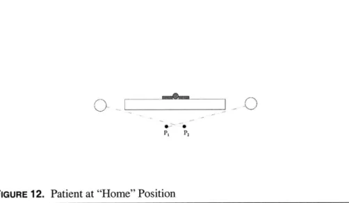
Bed-Bed/Chair Transfer
As in the case of rolling, initially, the arms are placed in their home positions.
P P2
FIGURE 12. Patient at "Home" Position
Then, one arm sweeps out to the edge of the bed/chair to which the patient will be transferred. See Figure 13. The rollers rotate in the same direc-tion. This causes translation of the patient. The sketches show that the rollers move clockwise, causing the patient to move rightwards.
Trajectory Generation
P,
P2FIGURE 13. Roller Actuation causes Translation.
As the patient nears the edge of the bed, the right arm moves further right to cause cradling of the patient and to enable transfer onto the bed/chair.
See Figure 14.
P, P
2
FIGURE 14. Coordination of Roller and Arm motion allows Translation.
The right roller continues to turn clockwise, pulling the patient. This motion is coordinated with the motion of the arm which travels further
Motion Planning
towards the right and aids the transfer of the patient from the bed he was orig-inally laying on to the new bed/chair.
Control of Actuators
Each roller and arm is assigned to an actuator. The actuators may be separately controlled in manual mode. Or, a pre-programmed file may be exe-cuted for the simultaneous motion of both arms and rollers. If a program
sequence is to be used, then all the actuators are first initialized. Equations
(13), (14), and (15) have been differentiated with respect to time and the
velocities are given by the following relations.
(-LI)cosa wcosy -sin _ 0
cosina-+y) sina -wsiny coscc +L (7Cos)
Cos(a-Y) -cos(c-y)+Mg Wcosy 0 cosy
For different values of the angle of tilt where the weight is assumed to be evenly distributed, that is, T, = T2, a number of data points have been
theo-retically obtained. They illustrate that the coupled roller rotations yield a mag-nitude in the range of 6 to 8 inches for a subject of width, 15 inches, and the positioning of the arms equally at 600. Sample trajectory has been generated.
Trajectory Generation
Sample Trajectory for Rolling, Arms Fixed at Specified Angle
7 6 0 W -3 0 2 1 1 2 3 4 5
Rotation of Right Roller, Phil 6
FIGURE 15. Sample Trajectory for Rolling Patient
If AC,, corresponds to the amount of sheet wrapped on either roller,
then initially, AC1 and AC2 are positive to enable the sheets to be taut on either side of the patient. Once the sheet is tight, the patient is firmly supported, then
AC1 increases whereas AC2 decreases. As sheet is wrapped around one roller, slack is introduced in the other. Slack introduction appears as a negative amount of wrap.
Figure 16 gives a simplified version of bed transfer where it is assumed that if both arms are kept horizontal and the rollers are actuated, then the sheet wrapping acts almost as a conveyor belt along the width of the bed.
7 8
Sample Trajectory for Translation, Arms Fixed at Specified Angle 20 18 16 14 12 10 8 6 4 2 0 2 4 6 8 10 12 14 16 18
Rotation of Right Roller, Phil
FIGURE 16. Sample Trajectory for Transferring Patient
The graph shows that as the sheet is wrapped around one roller, it is correspondingly unwrapped from the other exhibiting a simple linear relation-ship.
For a more interactive version of this prototype, communication between the sensors and the program commands will be established to enable response to various actions of the patient.
Motion Planning 16 00 0f * * * * * * * * * 20
CHAPTER 5
Implementation of First
Prototype
This chapter will consist of the following sections:
(1) Mechanical Design and Electronics
(2) Verification of Concept
(3) Verification of System Model
(4) Control Software Implementation
(1) Mechanical Design and Electronics
An initial prototype of the device has been built and tested. It does indeed allow rolling of patients. It has almost no setup time, only requiring the sticking of the bedsheet onto the roller via VelcroTM. It demonstrates both the ease with which the device may be set up above the bed and with which the patient may be transported.
Implementation of First Prototype 5 7
(2y
1 Frame 2 Gearmount 3 Roller 4 Arm, Type 1 5 Arm, Type 2 6 Gearbox, LP-90 7 Gearbox, LP- 155 8 McMC Spur Gears 9 Bottom Joi ner10 Edge Joiner 1 1 Leg, Type 1 12 Leg, Type 2
(1) Mechanical Design and Electronics
The design shown in the figure above has been chosen because it allows variation in both width and height without a significant increase in the cost of actuation. See Appendices B and C for complete assembly and part drawings. When the arms are rotated, not only do they change the height between the rollers and the patient but they also vary the width between the rollers. The former facilitates bed-bed or bed-chair transfer and the latter
accommodates for different-sized patients.
Selection of Materials and Determination of Design
A box frame is built for this prototype to demonstrate how the
machine would work on a regular bed. The frame is made in order to have a box-spring and mattress placed upon it. It is made up of square hollow steel tubes welded to one another to cover the drive tube, support its load via a bushing, and prevent any objects from either jamming or interfering in any manner with the driving of the arms. The final prototype could have the machine on casters so that it may be portable and may be wheeled around dif-ferent beds.
Choosing the drive shaft: The drive shaft is made of hollow stainless steel
tube with either end welded to a solid steel shaft having the same diameter,
1.75 in, but different lengths. The front and back solid steel shafts have
key-ways to allow transmission of torque to either of the arms as well as to the fol-lower gears. Both the arm ends and the gears have set screws to locate the position of the arms and gears on the drive shaft.
Implementation of First Prototype
0 = , (18)
GJ
where 0 is the deflection measured in radians, T is the torque, I is the length of the shaft, G is the modulus of rigidity of the material, and J, the moment of inertia is given by the equation
-= . (19)
DOWt is the outer diameter of the tube and Din is the inner diameter of the tube. A hollow tube is chosen instead of using a solid shaft because a hol-low tube has a larger moment of inertia than a solid one.
Steel is chosen for the tube because its properties suit the application. It has a large modulus of rigidity. Hardened steel would be ideal to minimize deflection. However, due to the large difference in cost, stainless steel was decided upon as a more reasonable option.
The deflection equation yields a range of deflection between 1-2*. Given that the length of the arm is 41.60 in, then, using the tangent of the
deflection gives the deflection of one arm with respect to the other resulting in
an absolute deflection in a range of 0.7-1.4 in. This amount of deflection, and hence misalignment between either end of the rollers, is deemed acceptable. It is expected to be absorbed by the limited elasticity of the aluminum rollers, the self-aligning bearings, as well as the flexible couplings.
Sleeves may be placed on the end of the drive shaft on the gearmount side to prevent the shaft from slipping away. Sleeves will not be placed on the other side of the shafts so as not to overconstrain it.
(1) Mechanical Design and Electronics
Hollow rectangular steel tube is used for the arms to minimize both torsion and weight in the arms. The lower ends of the arms are made of steel
and are welded to the hollow rectangular steel arms. The upper ends are also made of steel for welding. However, care is taken to ensure that they weigh as little as possible. This is to minimize the torque at the base of the structure. Even a small weight difference would cause a significant increase in the torque because, when multiplied by a large moment arm, the torque value shoots up.
On the gearmount side, the upper ends of the arms, shaped as cubes, have access windows cut out, both as slots and as squares. This is done to decrease the weight and also keeping assembly in mind. The access window is necessary because the flexible coupler consists of three separate pieces. One end of the coupler attaches to the gearbox shaft and the other to the shaft extending out of the roller. The gearbox shaft is not long enough to drive the roller itself. The access window allows one to attach the flexible coupler to the extending shaft easily.
The upper ends of the arms that are not on the gearmount side only contain the bearings for the roller to roll on. The arms are staggered from one another to prevent interference during their motion. The arms are maintained at the staggered distance by locating set-screws.
Holes may be drilled at the top of the hollow arms to allow electrical cables into the tube. The cables run from the gearbox and motors placed for roller actuation to the controller. Inserting the cables into the tubes would house the cables and significantly reduce chances of operators/ patients trip-ping or getting caught in the cables.
Implementation of First Prototype
The rollers are made out of hollow aluminum tubing. This ensures that they are lightweight yet their diameters are large enough to allow easy wrapping of the sheet. The roller has a cap - gudgeon - at either end of it and
a steel shaft going through it. The cap is long enough to drive the roller and a shaft extends out of it in order to go into the coupler. A rolled pin holds the cap and shaft in place.
Yaskawa motors were selected to be placed at the base for maximum torque. Gearbox LP-155 (Alpha Gear Manufacturers) with a ratio of 100:1 is compatible with Yaskawa motors to increase torque. Also, gearbox LP-90,
with a ratio of 50:1 is compatible with Yaskawa motors. Actual gears were chosen from the McMaster Carr catalogue to effectively double the torque
output at the gearbox shaft. Cost-effective and easily available gears were chosen. The base spur gear ratio was 2.38:1. This, along with the gearbox, results in a total gear reduction at the base of 238:1.
The gearmount - used to mount both LP-155 and the gears from
McMaster Carr - is made of aluminum, strong enough to bear the load of the
gearbox, yet light so as not to increase the overall weight of the machine. Bot-tom and edge joiners are welded to the box frame and then attached by bolts to the gearmount to minimize twisting when the forces between the drive and follower gears act to push them away from one anther. The bolt attachment allows for minor misalignments that may occur due to imprecision either in parts and machining, or during assembly.
The gearbox, LP- 155, has a spacer between it and the gearmount which serves a dual purpose. First, it positions the output shaft of the gearbox far enough away so as not to interfere with the motion of the arms without
(1) Mechanical Design and Electronics
causing a significant increase in the weight of the gearmount. Also, the spacer has a shoulder to allow the gearbox to rest onto it and to locate the gearbox with its location holes. The gearbox, LP-90, is mounted onto the arms on the
side of the gearmount, which is where the drive shaft is driven to minimize flexure at the end of the shaft.
Adjustable feet are attached to the bottom of the box frame to account for any misalignments that may be present on the floor. Also, the feet accom-modate imprecision in either the legs or the attachment of the gearmount. This reduces the cost since high precision is not needed during machining and assembly.
Electronics
Software, ServoWorks40 and the MCQuad Package, was obtained from Soft Servo Systems, Inc. It allows 4 axes actuator control and may be extended to 16 axes. This would be beneficial for when the system is extended to various functionalities, having a larger number of actuators for additional control of the patient and also for patient monitoring.The following figure more clearly illustrates the architecture of the ServoWorks software.
The FP-50 is a dual-link VersioBus Master Board inserted into a host
CPU and used to communicate with both the Servo and 1/0 Network. The 120 is a servo interface module that controls 4 axes, and upto four
DC-120s may be daisychained to increase the control capacity to 16 axes. The IM-200 us a general 1/0 module that provides 64 points of 1/0. It too may be dai-sychained with a total of 4 IM-200s.
Implementation of First Prototype
ISA Bus
FP-50 j VersioBuTM
VersioBuTM Servo Network 1/O Network
DC-1201 IM-200
Servo Drives 1/0 Devices
FIGURE 18. ServoWorks Architecture
Additional circuitry was designed to enable the control of the device in case of emergencies such as loss of control by the ServoWorks controller or
by computer failures.
Limit switches were purchased to ensure that the arms did not crush the gearmount if the controller lost control. The following circuit was
designed using a series of relays and switches as shown in Figure 19. It is cur-rently being implemented.
(1) Mechanical Design and Electronics
FIGURE 19. Electrical Circuit designed for Limit Switches
An external circuit connected to the motor supply with relays was used to control the power to the motors. If either of the limit switches is acti-vated, then both motors at the base of the bed will be switched off. Therefore, the relays are connected in series. The switching of both motors may, at first glance, seem unnecessary since the arms are never supposed to cross. How-ever, they are not allowed to cross if they are under the controller's control. If this is lost, then the right roller may actually try and travel towards the left limit switch. It may collide with the left roller, thereby causing a very unpleas-ant situation. So, if one limit switch is reached by either roller, the power to both motors is switched off preventing further mishap. When a limit switch is
Implementation of First Prototype
pressed, then the circuit is broken, the relay loses contact and the power to the motors is lost.
The limit switches used are normally closed (NC) switches to allow detection of any breaks in the circuit. If normally open switches were used, then, if there did exist another break in the circuit, one would not know about
it unless a limit switch was activated and it did not cut the power to the motors. This, however, would defeat the purpose of the limit switch because we would only know that it was not working after it did not work.
A "start", normally open (NO) switch is used to manually restart the
system once the limit switches are cleared. If the limit switches are not cleared, then pressing the start switch will not turn the motors on because the circuit would still be open by the limit switch.
An additional emergency stop "mushroom" switch could be included in this circuit design but it currently is not because the handwheel device pro-vided by Soft Servo Systems contains an emergency switch, that if needed, stops all the motors from functioning.
(2) Verification of Concept
Implementation of the first prototype verified the proposed and designed concept.
(2) Verification of Concept
The photographs illustrate the device in action. Initially, the machine is at its home position with the arms almost horizontal as shown.
FIGURE 20. Machine at Rest Position
---Implementation of First Prototype
The patient lies on the bed as shown and the arms are actuated to
position the rollers above the patient.
FIGURE 21. Patient lying on back in Bed
(2) Verification of Concept
The patient is lying on her back and the sheets are attached on either
FIGURE 22. Arm Positioned
side to the rollers via VelcroTM. The right roller - as viewed from the foot of
the bed - is rotated clockwise. Figure 23 shows the person slowly beginning
to roll onto her side.
Implementation of First Prototype
FIGURE 23. Patient beginning to tilt.
Since the left bedsheet has so far remained stationary, the patient
tends to lean onto it. Therefore, as slack is introduced in the left bedsheet the
patient rolls completely - with the aid of the momentum gained - onto her
(3) Verification of System Model
FIGURE 24. Patient Completes a Full Roll onto Stomach
The steps show that the device does indeed cause the patient to roll. If
patients are cooperative, then rolling is easily achieved. However,
uncoopera-tive patients, especially those with dementia, may require a modified
approach wherein the rollers are translated in the direction of rolling as
dis-cussed in Chapter 2, Figure
5.
(3) Verification of System Model
Implementation of First Prototype
ever, as will be demonstrated, the errors are allowable and patient trajectory may be obtained. Quasi-static equilibrium was assumed. This is the point when the person just becomes airborne. This assumption will need to be relaxed because the patient is never totally raised from the bed as patients tend to feel unsafe when completely airborne. Therefore, there will be shear and normal forces acting on the patient that are currently ignored.
The patient is modeled as a rigid body. This simplifies the analysis. However, it does not take into account the elasticity of patients. In fact, during rolling, one must realize that the patient appears to contract in width. This is due to the cushioning effect of human tissue and fat that flows and is partially compressible. The model presented does not take into account the elongation of the bedsheet as it helps roll the patient.
Measurements were estimated for certain sheet lengths and distances. Taking accurate measurements was relatively difficult. In addition to this, determining the "width" of the person was an issue. The patient was measured at the shoulders and the hips and an average of the two values were taken. There are inevitable errors in measuring because the rollers themselves are
assumed to be points. The sheet does not really meet the roller at its center, rather there is the distance that is actually the radius of the roller.
System Verification
Prior to the start of verifying the system model, the apparatus was cal-ibrated to determine the torque constant, k,. The motor manufacturers did pro-vide a value for this. However, it was for an AC motor but for my purposes, the motor becomes DC. A Hall effect sensor was placed at the motor and
(3) Verification of System Model
readings were obtained with (a) no weight applied to the roller, and (b) with a mass of 18.9kg attached to the roller. The following was obtained:
Input Current Mass (Peak Value)
No Mass I, = 0.3 A 18.9kg 12 = A
Using the following equation,
, = kI (20)
where T is the torque, and I is the current provided to the motor, two equations may be obtained. They are
Fir = kJ11 (21)
(F1 + F)r = k,12 (22)
where F1 is the weight of the system with no additional weight, F is
the added weight to the overall weight of the system, and r is the radius of the roller which is 1 in. Subtracting one from the other and rearranging the above equations gives
k, Fr (23)
I2(-11
Therefore, k, is determined to be 6.72Nm/A. So, the tension, TI, may be written as
Implementation of First Prototype
The theoretical value of T, is expected to be 490N -- when T2 is equal
to zero -- which is the weight of the author, the test subject used. The
experi-mental value obtained at the moment of rolling of the subject was measured to
be 424N.
TI, experimental = 0.87Ti, theoretical (25)
This shows that there is a close correspondence of the experimental value obtained to the theoretical prediction!! Furthermore, a sharp drop in T was observed at the moment of roll during experimentation. This gave clear indication that the person had indeed shifted weight from the left to the right. Verification of the model allows the trajectory generation for patients given their weights and widths.
A larger data set will be obtained. Currently, the model verified the
concept, and demonstrated that the model obtained is satisfactory. It allows the building of a generic control program to generate trajectory motion. How-ever, this needs to be perfected and an extended model should be designed. Furthermore, additional human subject testing will help in verification.
L, was expected to increase as slack is introduced. L2 appears to
decrease because it is measured from the right end of the patient who, while turning, moves closer to the right roller as it is lifted off the bed surface.
Rollers are placed as close to the width of the patient as possible. This was not predicted prior to the implementation of the first prototype. However, it was realized that placing the rollers with minimal horizontal distance between them helps in caressing the patient between the sheets and in placing
(3) Verification of System Model
him wherever desired. It enables the patient to easily be placed on his side. The sheets act to provide greater stability while being placed in this position.
As demonstrated by experimentation, the angle, a , reaches 900 when the person is tilted towards a side. This is to be expected. Since the rollers are placed as close as possible, then, as the patient is turned onto his side, the left
sheet meets the patient in an almost parallel direction.
Corresponding to the 900 value reached by angle, ux,
P
drops signifi-cantly in my calculations. This is because the angle is measured from the patient's right end that is closer to the right roller thereby decreasing theangle. However, this value was never really verified because obtaining a mea-surement for L2 was not a simple task. There was too much slack in the sheet. Also, it would be too subjective a decision to take as to where the sheet ended
- at the right end of the patient or underneath him.
The motor torques at the base may be monitored by the current input into the system. The torques would provide further information with respect to obtaining an extended model that accounts for shear and normal forces act-ing on the body.
Patient Translation
Patient translation was also verified. The arms were positioned at their rest, "home" position and the rollers were simultaneously actuated. The position of the person is located on the bed, as described by previous analysis and the person is translated laterally as in a conveyor belt system.
Implementation of First Prototype
When translating the patient sideways, the roller moves in the direc-tion of transladirec-tion and the fact that it moves upwards - in an arc - increases
the tension in the sheet helping the person to be translated.
(4) Control Software Implementation
The position loop gain and the smoothing time was tuned. PD control was used. The ServoWorks software and the handwheel device provided allows both the manual yet separate control of the motors. If desired, trajecto-ries may be generated by programming in G-code using the system model developed and verified earlier. The NC files created for the programs allow the simultaneous control of all four actuators.
The roller feedrates were adjusted to 1200mm/min. deemed to be a suitable rate to roll patients. Preliminary experiments showed that slow and steady motion was a priority in control so the positioning of the arms was also set to a relatively low speed of 1200mm/min. G-code was written for a person weighing 110 lbs and having an average width of 15 inches. The value for the program command of the roller, PCroller was determined using the equation:
PCroller = s x dpm x GRroier, (26)
27tr
where s is the amount of sheet wrapped around the roller, r is the radius of the roller, which is 1 in. for this prototype, dpm is the distance per
motor revolution which is set to 8192 jm, and GRroller is the gear ratio which is 50 for the rollers. The program command for the arm, PCarm, is given as
(4) Control Software Implementation
PCarm = x dpm x GRrm, (27)
where a is the arc length that the arm travels, R is the radius of the cir-cular trajectory, effectively the length of the arm which is 41.60 in. GRarm is the gear ratio which, as previously mentioned, is 238.
Motor 1, X - right roller Motor 2, Y - left roller Motor 3, Z - left arm Motor 4, A - right arm
(for right roller) (for left roller)
The arms were initialized to home position. The length of arm travel and roller wrap was determined and input into a program which was then exe-cuted.
The motions are defined as tabulated below.
TABLE 2. Motion Definition
Motion Description
X positive Clockwise rotation of right roller
Y positive Clockwise rotation of left roller
Z positive Clockwise rotation of motor, counterclockwise rotation of
left arm (supporting right roller), that is, arm moves up
A positive Clockwise rotation of motor, counterclockwise rotation of
right arm (supporting left roller) that is, arm moves down
It was determined that the arms could be positioned at the given parameters in the program, that is, close to the width of the patient and then the rollers could be actuated. The preliminary code used to successfully roll the author is shown as follows. Initially, since the bedsheet used is a full-sized sheet, first the left end of the sheet is attached to the left roller which wraps up some of the sheet in order to have enough sheet to later introduce slack to.
Implementation of First Prototype
Using the given software, the machine was taught a sequence of events. In fact, this was done inversely by first specifying the points in the code and then observing the behavior of the device. The desired coordinates were stored for use in generic programming. The home position was set to where the sheet would be attached to the roller. The left roller's home position was after two complete wraps of the sheet onto it. This allows enough sheet to introduce slack while rolling. The right roller's home position was set directly above the patient. The desired coordinates were recorded for when the sheet would be relatively tight at either end of the patient prior to commencement of rolling. This teaching was for patients ranging in widths of 15-19 inches.
The code for rolling the patient includes positioning of the arms, and initial uptake of slack in the sheet on either side of the patient.
The code for transferring the patient from one end of the bed to another assumes that the maximum length of translation of the patient will be half the width of the bed, from the center of the bed to either edge. Therefore, the maximum length of travel was assumed to about 20 in. The first line of code, however, is used to uptake any slack in the sheet prior to translation. The feedrate was increased to 4500mm/min because during testing, it was deemed that although slower is better for the skin on patients, an increase in the speed decreases a feeling of dizziness experienced by the author. This parameter may be left as a matter of preference and may be adjusted accord-ing to each person's wishes.
(4) Control Software Implementation
Control Code for Rolling and Transfer
Code for Rolling % Rolling (Generic) N100 G91 G01 Z202000 A-204000 F1500 N200 G01 X456270 Y-293316 F2500 N300 G04 P3000 N400 G01 X325907 Y114067 N500 G04 P2000 N400 G01 X325907 Y130363 N500 G04 P2000 N400 G01 X325907 Y195544 N500 G04 P2000 N600 G01 Y651814 M02
Code for Translation
%Translation
N100 G91 G01 X570337 Y-407384 F2500
N200 G04 P5000
N300 G01 X-1271037 Y-1271037 F4500
M02
These programs were used to automatically and successfully control the implementation of the first prototype.
CHAPTER 6
Conclusion
and
Future
Work
Discussion
The prototype built verified the proposed design concept. The device will indeed help to transport bedridden patients easily and comfortably. The benefits of using the bedsheet as the transport medium are manifold. First, patients experience lower stress concentrations. During initial pivotal rolling, the forces are distributed on a patient's body through the active sheet. This may be followed by a short period of airborne rolling helping patients to com-plete the roll as they lose contact with the bed surface. Second, shear forces exerted on patients, when moved from one edge of the bed to the other, are almost eliminated as they become airborne on the sheet and are moved over. Lifting does not introduce increased setup times as in currently available products. Since patients will scarcely be lifted off the bed surface, their fears are also reduced. Finally, the cradling aspect of the design ensures that the