Design and Applications of Cold-Cathode X-ray
Imaging Systems
by
Avilash Cramer
Submitted to the Harvard-MIT Program in Health Sciences and
Technology
in partial fulfillment of the requirements for the degree of
Doctor of Philosophy
at the
MASSACHUSETTS INSTITUTE OF TECHNOLOGY
February 2021
c
○ Massachusetts Institute of Technology 2021. All rights reserved.
Author . . . .
Harvard-MIT Program in Health Sciences and Technology
Oct 30, 2020
Certified by . . . .
Rajiv Gupta, MD/PhD
Associate Professor, Harvard Medical School
Thesis Supervisor
Accepted by . . . .
Emery N. Brown, MD/PhD
Director, Harvard-MIT Program in Health Sciences and
Technology/Professor of Computational Neuroscience and Health
Sciences and Technology
Design and Applications of Cold-Cathode X-ray Imaging
Systems
by
Avilash Cramer
Submitted to the Harvard-MIT Program in Health Sciences and Technology on Oct 30, 2020, in partial fulfillment of the
requirements for the degree of Doctor of Philosophy
Abstract
X-ray computed tomography (CT) and planar x-ray imaging are mainstays of modern clinical care. The electron generation mechanism in standard x-ray tubes - specifically, a thermionic cathode - is reliable and capable of high current. However, thermionic cathodes are bulky, and cannot be pulsed quickly. Non-thermionic (’cold-cathode’) electron generation can be exploited to make a smaller and rapidly pulsable x-ray source. Such an x-ray source could improve not just the portability of x-ray devices, but would allow for a CT system to operate by pulsing a distributed ring of x-ray sources instead of rotating a single large x-ray source.
Furthermore, cold-cathode x-ray sources could allow for new signal acquisition and processing paradigms in the x-ray domain. This includes time-based image acquisition techniques, such as elastography and photon-counting measurements.
In this dissertation, I discuss (1) the development of two novel types of cold-cathode x-ray sources: an ultraviolet photocold-cathode-based source, and a silicon field emission chip; (2) novel methods for planar x-ray image acquisition, including a demonstration of dynamic x-ray elastography using a pulsed photocathode x-ray source; and (3) applications of modern signal processing techniques to the tomo-graphic image reconstruction problem.
In an epilogue, I discuss our research on N95 respirator sterilization and re-use for crisis situations.
Thesis Supervisor: Rajiv Gupta, MD/PhD
Funding Acknowledgements
I was supported by the National Institute of Biomedical Imaging and Bioengineer-ing (NIBIB), of the National Institutes of Health under award number 5T32EB1680; by the US Army Medical Research Contract Acquisition Activity under award num-ber W81XWH-15-C-0052; by the Eran Broshy Fellowship in Medical Engineering & Science; and by the Hugh Hampton Young Fellowship of MIT.
Acknowledgments
I want to give specific credit to the people below who helped me through the research process over the last five years:
- Gupta lab members and alumni: Wolfgang Krull, Tim Moulton, Dr. Xiaochun Lai, Tim Boers, Dr. Dufan Wu, Dr. Kai Yang, Alankar Kowtal, Jaime Caines, Gerard Snaauw, Jake Hecla
- NASA’s Goddard Space Flight Center: Steve Kenyon, Dr. Zaven Arzoumanian, Dr. Keith Gendreau
- Raskar lab members and alumni: Dr. Achuta Kadambi and Tomohiro Maeda - MIT Nuclear Science and Engineering: Dr. Leigh Ann Kesler, Pete Stahl, Dr. Cody Dennett, Steven Jeapal, Dr. Michael Short, Enze Tian, Dr. Ju Li
- MIT EECS: Dr. Winston Chern, Dr. Girish Rughoobur
- A.A. Martinos Center for Biomedical Imaging: Dr. Bruce Rosen, Dr. Bo Zhu, Dr. Neha Koonjoo, Dr. Abbas Yasseen, and Dr. Ken Chang.
- PanFab: Deb Plana, Helen Yang, Dr. Nicole LeBeouf, Akshay Kothakonda, Dr. Michael Sinha, Dr. Sherry Yu, Dr. Peter Sorger.
I owe also a great deal to my thesis supervisors,
- Dr. Rajiv Gupta, at Harvard Medical School, for his guidance and leadership in the last few years, and his encyclopedic knowledge of the history, systems, and practice of radiology.
- my committee, Drs. Mathew Rosen, Richard Lanza, and Ben Vakoc, for their support and guidance.
And finally, I would not be here without all the friends and family who kept me sane:
- family: My parents, Alan Cramer and Jayashree Kalpathy-Cramer; my grand-parents, Ananathy and Krishna Kalpathy, and Marcia Cramer; my girlfriend, Steph; and all of the Cramer family cousins, aunts, and uncles.
Manuel Morales, Dr. Jesse Kirkpatrick, John Samuelsson, Dr. Shriya Srinivasan, Aditi Gupta, Sri Gowtham Thakku, Vamsi Mangena, Aditi Gupta, Ellen DeGennaro - the ski buddies: Jimmy, Magua, Nico, Lulu, Colin, Neil, Ben Eck, Laura, Parrish, Dylan, Colie; and in memory of Ben Kessel.
- the climbing buddies: Hannah Varner, Liane, Asha, Chris, Nathaniel, Danielle, Max, Hannah Lippe, Evan, Alex, Eric Kirchner, Kesley Wittels, Erik Knall, David Chang, David Cain, David Migl, Mason, Cole, and many, many more.
Dedicated to my parents Avilash Cramer
Contents
1 Introduction 19
1.1 Volumetric Imaging Techniques . . . 21
1.1.1 Conventional CT . . . 21 1.1.2 PET . . . 24 1.1.3 Ultrasound . . . 25 1.1.4 MRI . . . 25 1.2 Clinical Motivation . . . 26 1.2.1 Disparities in Access . . . 26 1.2.2 Stroke Management . . . 26
1.2.3 Traumatic Brain Injuries . . . 28
1.2.4 Tomosynthesis applications . . . 29
1.3 Technical Background . . . 30
1.3.1 X-ray images . . . 30
1.3.2 X-ray production . . . 34
1.3.3 Electron generation techniques . . . 37
1.3.4 Ultraviolet Photocathodes . . . 38
2 Cold-cathode X-ray source design 41 2.1 Stationary Computed Tomography for Space and other Resource-constrained Environments . . . 41 2.2 A Digital Pulsed X-ray Source Based upon Si Field Emitter Arrays . 60
3 X-ray image acquisition 71 3.1 Using Document Scanners to Make Digital X-ray Images . . . 71 3.2 Dynamic X-ray Elastography using a Pulsed Photocathode Source . . 81 3.3 Statistical Photon Arrival X-ray Imaging (SPARX): A Proposed Method
for Low-Dose X-ray imaging . . . 90
4 Tomographic Image Reconstruction Techniques 105
4.1 Signal Sensing and Reconstruction Paradigms for a Novel Multi-source Static Computed Tomography System . . . 105 4.2 AUTOMAP for CT: Reducing the Number of Projections in CT
Imag-ing UsImag-ing Domain-Transform Manifold LearnImag-ing . . . 114
5 Conclusions and Future Work 121
5.1 Conclusions . . . 121 5.2 Future work . . . 122
6 Epilogue: medical engineering in the pandemic 125
6.1 Assessment of the Qualitative Fit Test and Quantitative Single-Pass Filtration Efficiency of Disposable N95 Masks Following Gamma Irra-diation . . . 126 6.2 Analysis of SteraMist ionized hydrogen peroxide technology as a method
List of Figures
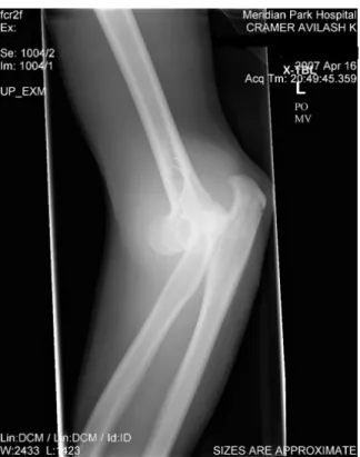
1-1 X-ray radiograph of the author’s arm following a regrettable rock climb-ing incident. . . 32 2-1 Schematic of the miniature x-ray source. A pulsable UV LED (1)
emits UV photons which pass through a quartz window (2) into the vacuum manifold (4) and interact with a photoemissive magnesium film (3). This interaction produces electrons which are amplified by a Channeltron device (6), which is supplied with a 3kV bias voltage (7). The amplified electrons are accelerated through a large electric field provided by an external high voltage source (8), and impact on an angled tungsten target (9). This interaction (10) produces x-ray photons which leave the vacuum manifold through a beryllium window (11). . . 55 2-2 A: Cut-through CAD model of the module B: Isometric view with a
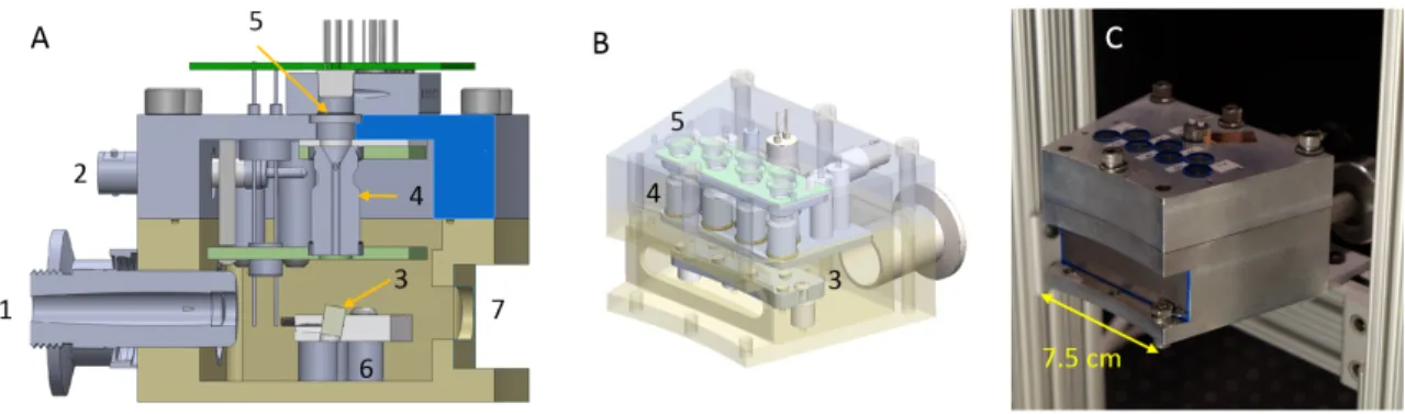
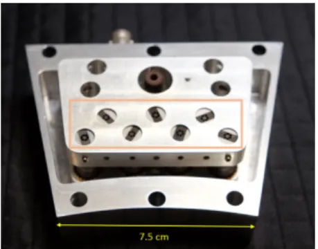
transparent outer housing C: Completed x-ray module with a beryllium sheet covering the x-ray window.(1) Vacuum connector (2) 3kV bias line (3) tungsten targets (4) Channeltron electron amplifiers (5) quartz windows (6) High-voltage anode plate (7) x-ray window . . . 55 2-3 Internal view of the module, with the exit ports of the Channeltrons
highlighted. . . 56 2-4 A: X-ray projection image of pig lung with an inserted catheter. B:
axial slice from pig lung reconstruction. C: segmented bronchial tree from pig lung. . . 56
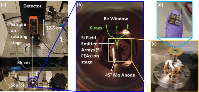
2-5 CAD diagram of full ring of modules, with dimensions . . . 57 2-6 Populated LED control PCB . . . 58 2-7 (a) Photograph of the x-ray test setup with a multimeter as the test
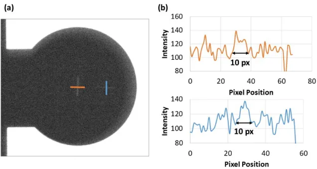
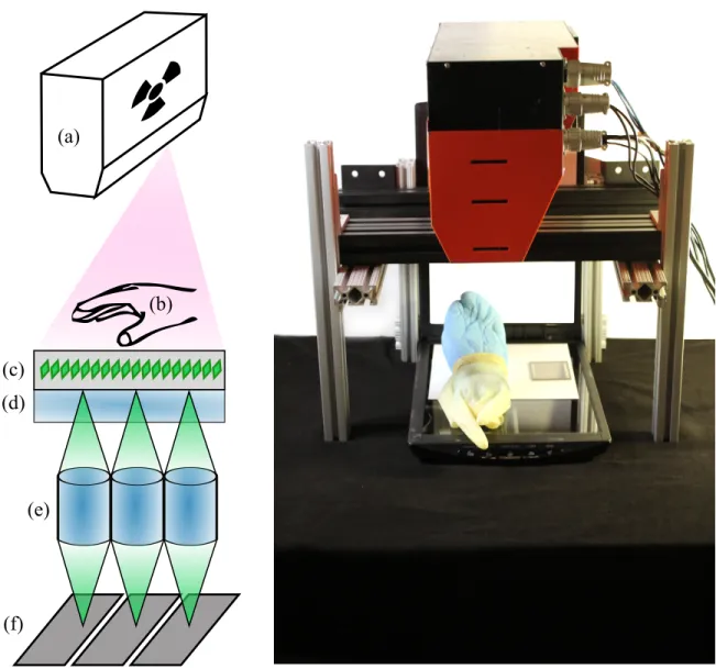
sample which sits on a rotating stage. The source is approximately 55 and 77.5 cm from the sample and detector, respectively. The x-ray source (b) is a bremsstrahlung source housed in a small vacuum chamber with a small ion and turbo pump with a Si field emitter arrays (Si FEAs) as the electron source and a molybdenum anode biased at high voltage; the x-rays travel out towards the sample through a Be window. The base pressure of the system is roughly 10−8 Torr and operates at roughly 10−7 Torr when active. The (c) electron source is a (d) Si FEA chip containing (Die size: 7x7 mm2) and three wire-bonded devices. The cathode or substrate of the Si FEA chip is mounted to feedthrough using silver paint and wire-bonds are used to connect the gates to individual feedthroughs . . . 64 2-8 (a) X-ray image of two 10 𝜇m slits used to measure the effective focal
spot size of the source. The image was taken with a 2x magnification and the 500x500 𝜇m2 device to test the focal size limitations of the
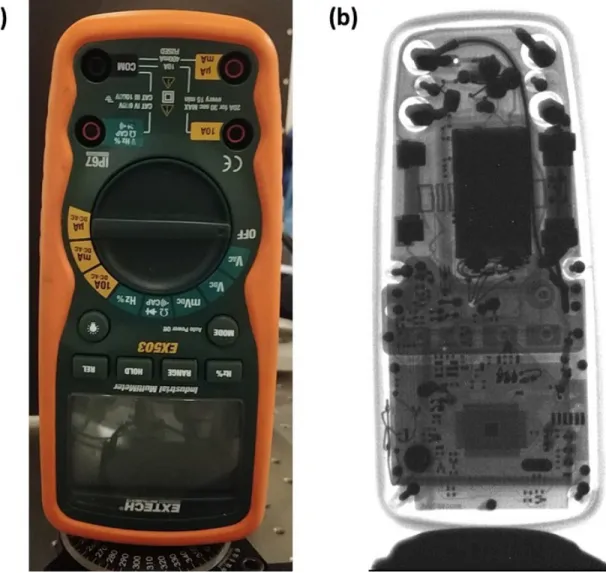
FEAs. (b) Line scans of the intensities were used to derive the focal spot size of the source based upon the number of pixels. It was observed that the worst-case number of pixels is approximately 10 pixels or roughly 600 𝜇m, indicating minimal size increase in the focal spot size despite not having any focusing optics. . . 66 2-9 . (a) Optical and (b) 2D x-ray image of a multimeter taken using a
1000 x 1000 𝜇m2 source at 38 kVp with a pulse width of 200 ns, V𝐺 =
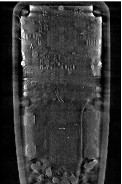
57 V and a period of 20 𝜇s. The total exposure time was 1s or 50000 pulses . . . 67 2-10 Slice of the multimeter from the 3D reconstruction at board level.
Bright features indicate the presence of metal which has enhanced ab-sorption relative to other materials in the multimeter . . . 68
3-1 Using a document scanner as a digital X-ray detector. X-rays are emitted from the overhead-mounted source. The cadaver hand and a resolution chart lay on the scan bed. (a) X-ray cone beam; (b) object to be imaged; (c) scintillation screen emitting green light; (d) scanner glass (or optional lead-doped glass to block X-rays); (e) self-focusing gradient lens; (f) pixels on linescan sensor. . . 73 3-2 X-ray image of a cadaver hand using a Canon○R LIDE 220 document
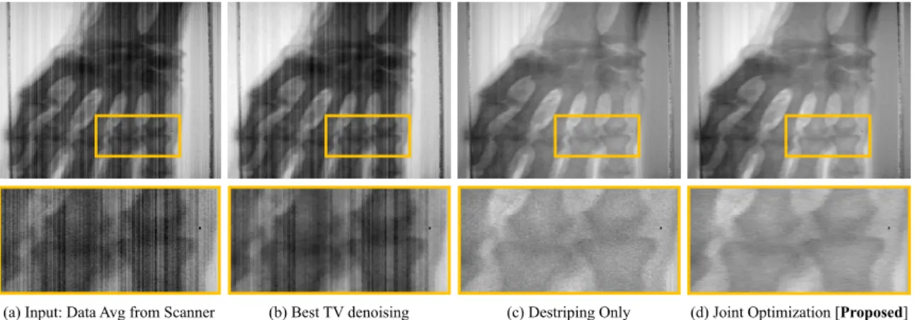
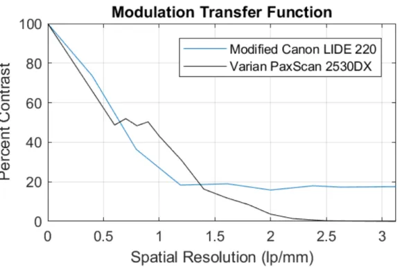
scanner. (a) An averaged composite of 100 individual scans used as input to denoising methods (b-d). The proposed approach is (d). Inset image: proximal inter-phalangeal joint. . . 76 3-3 Modulation transfer functions for the modified X-ray scanner we
con-structed and a commercial flat panel X-ray detector. . . 81 3-4 A pulsed 255nm UV LED (1) is used to illuminate a magnesium thin
film through a quartz window (2). The thin film, shown in green color, is deposited on a glass electron multiplier (4). The photocathode and anode are both contained within a vacuum manifold (3) pumped down to 10-7 Torr by a turbo pump and sealed by a beryllium window (8). The output electrons of the photocathode (6) are accelerated through a high voltage supplied by (5) to a tungsten target anode (7), producing x-ray pulses through the Bremsstrahlung process. These pulses illuminate a phantom (9), depicted in detail in Fig 2. The phantom is vibrated pneumatically by a speaker synchronized with the UV LED. The images are acquired at different phases of the vibration by a flat-panel detector (10). . . 83 3-5 A photograph of the setup. . . 84 3-6 Image acquisition sequence for dynamic x-ray elastography using a
pulsed x-ray source. . . 84 3-7 Hitohada gel embedded with ZrO2 particles and a 25 mm diameter
3-8 (a), (b), (c), (d), and (e) show the displacement maps with 0, 2/5 𝜋, 4/5 𝜋, 6/5 𝜋, and 8/5 𝜋 radians of phases, respectively. (f) and (g): Maps of storage and loss moduli, respectively . . . 88 3-9 An experimental schematic of the setup. A pulsed X-ray source and
SPAD camera are critical. To image the entire FoV of the object, the apparatus would need to be translated (not shown) . . . 92 3-10 A photon is probabilistically identified as a scattered or ballistic
pho-ton based on a mixture model of distributions. The distribution will depend on the hardware configuration, X-ray energy level, and the type of tissue being imaged. . . 95 3-11 In the noiseless case, the proposed results are similar to the
state-of-the-art [127]. . . 96 3-12 Performance at 10 dB, 20 dB, and 30 dB of scattering. . . 97 3-13 Methods used to extrapolate LIDAR flux to X-ray flux. First, the
quality metric of contrast-to-noise (CNR) ratio is chosen. Second, pairs of comparable regions are identified in each of the X-ray and LIDAR images, selected for their contrast ratio being equal. These regions are shown in the white squares overlaid on the images. In computing CNR on these regions, it is observed that the quality of the LIDAR data has one-fifth the CNR of a medical-grade scan. Under a Poisson noise model, a 25-fold increase in the LIDAR exposure would achieve equivalent CNR between the two images. . . 99 3-14 Clinical lung x-ray with ROI between upper lung and adjacent rib
shadow. A dataset of six such, deidentified images were obtained from the Massachusetts General Hospital. . . 101 3-15 LIDAR image with ROI marked. The contrast between teh two squares
in this image correspond to the contrast between the two squares in Figure 3-14. The LIDAR data is provided by Shin et al [127]. . . 101 4-1 A typical CT system versus the proposed system . . . 107
4-2 Photon deprivation with one source ON at a given time. (a) Imaged axial slice through a human brain, and a typical projection image with the X-ray source on top. (b) Photon rate seen in a noiseless measure-ment by a subset of detectors. The rate is smallest at a point opposite to the source because light traverses the most amount of tissue. Here, the minimum rate is ∼ 2.5 photons per exposure. . . 111 4-3 The ground truth CT slice (top row), a slice reconstructed from the
simulated low-power static CT (middle row), and a slice reconstructed from a simulated, 200kW traditional CT scanner (bottom row). Both the bone (left) and brain (right) window levels are shown. For the simulated static CT system with parameters in Section ??, the image quality metrics were RMSE = 6.36%, SSIM = 0.98 as compared with RMSE = 1.13% and SSIM = 0.999 for the high-power traditional CT. 113 4-4 Ground truth slice in bone (a) and brain (b) window-level setting, slice
reconstructed using the low-power static CT (c) results in RSME= 8.74% and SSIM = 0.976, and slice from a simulated high-power tra-ditional CT (d) resultin in RSME = 1.83% and SSIM = 0.999. . . 114 4-5 Layers of AUTOMAP, as used for CT . . . 116 4-6 Hardware approaches for scaling AUTOMAP . . . 117 4-7 Comparison of dAUTOMAP and FBP SSIM loss, average on a 10,000
image testing set. . . 119 4-8 Comparison of dAUTOMAP and FBP SSIM loss, average on a 10,000
image testing set. . . 119 6-1 Box plots show data from a given particulate size for N95 masks that
received 0, 1, 10, and 50 kGy gamma radiation doses from a cobalt-60 source. Tops and bottoms of boxes denote 75th and 25th percentiles, respectively. Lines within boxes denote medians. Circles denote out-liers. Error bars were calculated by 6 observations of the upstream and downstream particle concentration. . . 128
6-2 Single-Pass Filtration Efficiencies for Ambient Particles of Irradiated N95 Masks . . . 129 6-3 Commercial vaporization and ionization-based hydrogen peroxide
ster-ilization technologies, . . . 132 6-4 Results obtained at a university laboratory on single-pass filtration
efficiency for ambient particle matter. Each row represents a single N95 mask. Filtration efficiency values are an average of four upstream and downstream measurements. . . 140 6-5 Results from ICS Laboratories on instantaneous filtration efficiency
according to NIOSH standard Procedure No. TEB-APR-STP-0059. Each row represents data from 1-5 N95 masks and data are reported as the average for all tests that were performed. . . 141 6-6 Results from ICS Laboratories on full loading filtration efficiency
ac-cording to NIOSH standard Procedure No. TEB-APR-STP-0059. Each row represents data from an N95 mask. . . 141 6-7 Instantaneous and fully-loaded ambient particulate matter filtration
data for N95 masks over one, two, and five SteraMist sterilization cy-cles. Results were obtained from ICS Laboratories according to NIOSH standard Procedure No. TEB-APR-STP-0059. All masks passed ICS standards, including filtration efficiency of 95%. . . 142
List of Tables
1.1 Common scintillators in medical imaging . . . 33 1.2 K-line of common anode element choices for x-ray imaging . . . 36 1.3 Tube voltages and spot sizes for different medical x-ray applications . 36 3.1 SPARX is estimated to reduce the radiation dose by an order of
Chapter 1
Introduction
Imaging modalities such as radiography, computed tomography (CT), ultrasound, positron emission tomography (PET) and magnetic resonance imaging (MRI) are an essential component of medical practice. Planar X-ray radiography is required for diagnosing many diseases such as tuberculosis, pneumonia, pneumothorax, and fractures. As a rapid and volumetric imaging technique, CT is an invaluable part of emergency medicine and inpatient care. CT is also essential in planning radiation therapy treatments. MRI, another volumetric imaging technique has better soft tissue contrast than CT. However, it can take substantially more time for acquisition, is even more expensive and harder to maintain.
The performance of these medical image acquisition devices has steadily improved in recent decades in nearly all measurable parameters such as resolution, scan time, number of clinical applications, ease of use, and patient safety. Unfortunately, a majority of world’s population still has no access to radiology systems of any kind, let alone advanced imaging such as MRI or CT. While the reasons for these disparities are multifaceted, one factor that cannot be dismissed, is the cost and complexity of radiology tools. While cell phones, internet, computers, audio and video devices, and many other sophisticated consumer electronics have seen constant decrease in the price/performance ratio, no such trend is perceptible in medical imaging.
Even though X-ray technology is over 120 years old, planar radiography is only available to roughly 1/3 of the world’s population. Many underserved areas - urban
and rural - lack this basic diagnostic tool because of its cost, maintenance, power, and personnel requirements. Furthermore, plain film radiography has largely been replaced by digital radiography in high-income nations where it has become the de facto standard for X-ray imaging. Digital radiography offers a number of advantages compared to film-based X-ray imaging, which include lower lifetime costs, ease of image processing and archiving, and the potential for teleradiology. Despite these advantaged, the adoption of digital X-ray imaging has been much slower because of the high initial cost of digital x-ray detectors, which is typically on the order of USD $10,000.
CT is used to diagnose many emergent medical conditions, including stroke and traumatic brain injuries [43, 100]. Recently, CT system provided an essential method of diagnosing COVID-19, especially in the early stages of the pandemic when PCR based test kits were not widely available.[CITE AJR], and are still used extensively for this purpose in China and Europe.
Unfortunately, the size, weight, and expense of CT systems – which involve a roughly 2 ton spinning gantry [62, 132] - make them largely inaccessible for patients outside of major hospitals centers.
From a global perspective, there is only approximately 1 CT scanner per million people (pmp) in Colombia as compared to over 64 per million in Australia, and 44 pmp in the US. Across all OECD nations, there is an average of 15.6 pmp compared to an average of 0.29 per million in low-income nations. Common prices for CT scanners are between USD $500,000 and $2 million [95].
Similarly, the United States has 36.7 MR scanners pmp, while Colombia has 0.2 pmp. Amongst the Sub-Saharan African nations there are collectively 0.04 MR scan-ners pmp - roughly 1/1000th the rate of the US. MRI scanscan-ners typically cost on order of US $2 million. For many conditions such as brain tumors, acute stroke, and many other conditions that require good soft tissue contrast, an MRI scanner is indispensable. It also does not expose a patient to ionizing radiation. However, it is dependent on acheiving a 0.2 - 3 Tesla magnetic field, with many research scanners going as high as 7T (and higher for some animal magnets). In most modern
high-filed MR scanners, high strength magnetic field is achieved by a liquid helium-cooled superconducting magnet. Maintaining a superconducting magnet at 4 Kelvin is an expensive and resource-intense task requiring continuous power, frequent refilling of liquid nitrogen, and occasional refilling of liquid helium. An unexpected rise in the core temperature — whether by electrical or mechanical failure, or human error — can cause the superconducting magnet to quench. Such an event can easily destroy the MR scanner and result in harm to patients and personnel [37].
In addition to the national disparities between LMICs and HICs, these imaging resources are unevenly distributed in most countries because a host of factors such as income or population distribution, geography, government regulations. Even within the US, many communities lack access to basic healthcare facilities including the medical imaging support required by them. In addition to cost and complexity of the devices themselves, infrastructure issues such as the lack of adequate roads, inconsis-tent or nonexisinconsis-tent power grids, water supplies, and Internet access, limited numbers of trained radiologists and technicians add to the difficulties of using advanced imag-ing technology.
Many teams around the world are researching low-cost imaging solutions to ad-dress the access and availability issues plaguing advanced imaging modalities.
In this thesis, I present a body of research centered on improving the accessibility of CT scanners. Specifically, our approach is based on the development and use of new types of x-ray tubes: ones that use a non-thermionic "cold-cathode" electron genera-tion mechanism. These sources are significantly smaller and lighter than convengenera-tional x-ray tubes, and can be pulsed quickly.
1.1
Volumetric Imaging Techniques
1.1.1
Conventional CT
Computed tomography (CT), also known as computed axial tomography (CAT), is a versatile 3D x-ray imaging modality. It is the diagnostic standard for the management
of stroke, traumatic brain injury, and many other emergent conditions. More broadly, multi-angle tomosynthesis - passing an x-ray beam through a sample and measuring its intensity at a multitude of angles around a common axis - is used in a variety of medical and industrial applications. Tomosynthesis produces a data set consisting of a large number of projections through the same cross-section at different angles. ’Tomography’ is generally used to refer to volumetric imaging from a full ring of acquisition angles, while ’tomosynthesis’ generally refers to a volumetric imaging from an arc (’limited angle’) of acquisition angles. Computational algorithms such as the inverse Radon transform are then used to create an attenuation image of the cross-section from the series of projection images [62].
Conventional CT systems use a large thermionic source mounted opposite a de-tector on a helical gantry. Images are acquired from hundreds of angles as the gantry spins at up to 300 rpm. As such, the spinning gantry is a substantial mechanical and electrical engineering challenge.
The design and construction of clinical CT has undergone several changes over the years. First generation CT system used a pencil beam x-ray source, and a single detector that rotated opposite the source. The detector and source would move both linearly and radially to get a full image, an acquisition scheme known as ’translate-rotate’. The slice thickness (z-axis resolution) was determined by collimator settings on x-ray tube. First generation CT scanners had a 25-30 minute scan time.
Second generation CT replaced the pencil beam with a fan beam x-ray source. An asymmetrical spot size (created by angling the anode target relative to the electron beam) is used to reduce dose outside the detector field of view (FOV) for each acquisi-tion. As in first-gen CT, second gen used a ’translate-rotate’ acquisition scheme, but with multiple detectors in an array opposite the source rather than a single detector. Having a larger fan beam and multiple detectors reduced the scan time to around 90 seconds.
In third generation CT, a large fan beam x-ray source is used, with large detector array that moves opposite the source. The x-ray irradiation area is large enough that no translation required, as the fan entirely encompasses the patient. 3rd generation
CT scanners also saw the introduction of a helical slip ring, a mechanical gantry system where x-ray sources trace a single helical path around the patient, allowing for very fast scan times (on the order of 30 seconds for a whole body scan). 3rd generation CT is widely adopted as the standard in modern hospitals.
Fourth generation CT is very similar to 3rdgeneration CT, with the key difference that the detector array comprises a full 360 degrees, meaning that no detector motion is required [62, 132].
Recently, dual energy CT have been introduced in hospitals as well. In dual energy CT, a single area is imaged with x-rays at two different energies. The difference between the two resultant images can provide additional contrast. Dual energy CT imaging is accomplished using two sources at different voltages and angles, or else a single source that is quickly switching between two voltages [58].
While a large number of variations exist on the general principle, nearly all use a moving gantry holding a thermionic x-ray source. Some non-rotating CT concepts have been realized using electron accelerators and a magnetically steered beam aimed at a large ring anode surrounding the target object, although they have not yet been widely adopted, for technical and economic reasons.
CT can be combined with an intravenous contrast agent, such as iodine, in a technique known as CT angiography (CTA). CTA is a quick and robust method of visualizing blood vessels.
It is worth comparing and contrasting CT to three other volumetric imaging modalities: ultrasound, magnetic resonance imaging (MRI), and positron emission tomography (PET). While MRI and ultrasound deliver no ionizing radiation, the typical dose1 delivered to the patient for a head CT is 2-4 milliSieverts (mSv), and
for an abdomen CT is 10-20 mSv. For PET, the typical dose is on the order of 7 mSv. The average American receives a yearly radiation dose of 6.2 mSv, roughly half of which comes from medical procedures.
If the linear-no-threshold (LNT) model of cancer risk is to be believed, it is possible that up to 2 percent of all cancers in the US are caused from radiation delivered by
CT alone [15]. However, that figure is debated [140, 130], and assumes a whole-body, uniform dose from computed tomography; the LNT model of cancer risk is itself widely disputed. While this debate is unlikely to be resolved as a controlled trial of human radiations would be unethical and impractical, but the minimum yearly dose clearly linked to an increase in cancer risk is 100 mSv.
In any case, CT also has many advantages over MRI. CT is a much quicker procedure than MRI. Additionally, MRI is contraindicated for patients with embedded shrapnel, cardiac pacemakers, or other ferrous metal implants, as they are a significant burn and trauma risk in the presence of powerful magnetic fields. MRI, PET, and CT are unavailable for bariatric patients who cannot fit in the bore of the respective imaging system (typically on the order of 80 cm). Many CT and MRI protocols use a contrast agent, which also presents the risk of an adverse reaction in the patient.
1.1.2
PET
Another volumetric medical imaging technique is positron emission tomography (PET). In PET imaging, a solution containing a molecule (commonly a sugar, such as raclo-pride) tagged with an unstable radioactive isotope is injected into the patient. As the isotope decays, it releases a positron (an electron anti-particle), which annihilates an electron and release two 511 keV gamma rays in opposite directions. A ring of of high-speed gamma ray detectors surrounds the patient. By recording simultaneous detections, it is possible to form a 3D intensity map of the tagged molecule. PET is a powerful tool in that it can provide physicians and scientists with biochemical activity information within the body. However, since images are a stochastic map of the location of tagged molecules, the poor anatomical from PET images is quite poor [96, 88].Because of that, PET is often combined with another imaging modality, such as CT.
1.1.3
Ultrasound
Ultrasound is a medical imaging modality that uses the reflection of high frequency (1-18 MHz, depending on the application) sound waves to image soft tissue. Ultrasound has essentially no medical risk (such as from ionizing radiation or contrast agents), and is highly portable- as such, it is often the preferred imaging tool in low-resource environments. However, ultrasound is limited in its ability to penetrate deep into tissue or bone [80, 79]. Ultrasound imaging is commonly used in the US in conjunction with x-ray mammography, and for obstetric imaging. Portable ultrasound has a variety of uses, including for imaging vasculature.
1.1.4
MRI
In MRI, a large magnetic field (typically 3 Tesla) is used to align a small fraction of odd-numbered nuclei within the patient. A radio frequency (RF) pulse at the Larmor frequency of the protons in the magnetic field is used to flip a fraction of the aligned nuclei to a higher-energy state. As the particles ’relax’ to the lower energy state, they emit an RF pulse at the same frequency. The delay before this second pulse is emitted is known as the relaxation time, and is dependent on the interaction of individual protons with charged particles in their vicinity. Different tissue types have different proton densities and thus different relaxation times. This diversity in relaxation times provides the contrast in MRI images.
The primary advantage of MRI is its ability to provide good soft tissue con-trast. MRI has been a mainstay of both neuroscience research and neurology care for decades, as well as the assessment of joints, spinal injuries, and many others.
Simultaneous PET/CT, PET/MRI and MRI/CT system have all seen use in re-cent years [118, 83, 94]. PET provides activity data, but poor resolution and anatomic data. CT provides anatomical information, and in conjunction with an intravenous contrast agent (CT angiography), can provide an excellent visualization of bone and blood vessels. MRI provides exceedingly high resolution anatomical data as well as soft tissue contrast.
However, the engineering challenge of having multiple modalities image the same subject without interfering with each other is non-trivial, and additional imaging procedures can have risks of their own, especially if they involve ionizing radiation. The use of PET/CT for oncological management in young people, in particular, has been critiqued [54]. Regardless, a smaller form-factor CT system could be more easily combined with other imaging systems.
1.2
Clinical Motivation
1.2.1
Disparities in Access
Worldwide, some three-quarters of the global population has no access to medical radiography of any kind, let alone computed tomography. This relative paucity of radiography equipment extends not just to advanced systems like MRI and CT, but also to simple projection x-ray imaging, leading to a widespread inability to diagnose virulent and debilitating conditions such as tuberculosis [129]. The disparities in access for volumetric imaging are even more acute. In OECD2 countries [95], there
is an average on 1 CT scanner per 65,000 people. In low-income countries3, there is one CT scanner per 3,500,000 people.
1.2.2
Stroke Management
Even in high-income nations, CT systems are generally only available in major trauma center hospitals, and need to be supplied with continuous, 3-phase power. This lack of portability contributes the particular challenges of healthcare delivery in rural com-munities, but affects pre-hospital care in essentially every demographic community.
CT is used to diagnose a wide variety of illness and injuries: traumatic brain in-juries, pulmonary embolisms, even appendicitis4. One especially common pathology 2Organization for Economic Co-operation and Development, a collection of 35 mostly high-income
nations
3Defined as having a per capital Gross National Income of less than $1005 (2016 dollars) 4As the author can attest from a June 2017 incident
where CT helps guide critical medical decision making is stroke. Stroke - hypoperfu-sion of brain tissue - is the second leading cause of death worldwide and the leading cause of disability in the US. Stroke symptoms include one-side paralysis, slurring, vertigo, and many others. Even when survived, strokes often result in permanent brain damage. Timely interventions are crucial to stroke management [119].
Strokes come in two broad flavors: hemorrhagic (bleeding) and ischemic. Ischemic strokes can be further subdivided5 into two subcategories: thrombotic (caused by a clot), and embolic (caused by a embolus, a catch-all term for a variety of blockages). In ischemic strokes, timely treatment by thrombolytic drugs (such as recombinant tissue plasminogen activators) can be critical step to saving lives and brain tissue. However, in a hemorrhagic stroke, one of the blood vessels inside the skull is bleeding, filling a portion of the cranial cavity with blood. In the case of a hemorrhagic stroke, delivering thromobolytic drugs would be a devastating and possibly fatal mistake. Distinguishing between ischemic and hemorrhagic strokes is accomplished through neuroimaging.
As per the MGH stroke management guidelines [43], patients with symptoms indicative of a stroke first receive a non-contrast CT to determine if the stroke is hemorrhagic or ischemic, and to rule out a non-stroke pathology (termed a ’mimic’)6. In the case that the stroke is ischemic, patients receive an intravenous contrast injec-tion, and CT angiography scan. This is done to visualize the occlusion, and the extent of the occluded area. Finally, a diffusion weighted MR image (DWI) is performed to determine the extent of tissue death, and subsequently whether a given patient is a candidate for more invasive, mechanical removal of a thrombus/embolus. Variations of this protocol are used in hospitals around the world [131, 57, 14, 121, 78].
Given the importance of CT in stroke management, and the widespread prevalence of strokes, one of the most convincing applications for a mobile CT scanner is the prompt diagnosis of stroke. A CT scanner that could fit in an ambulance could possibly allow paramedics to distinguish between hemorrhagic and ischemic strokes, 5Technically, systemic hypoperfusion (low-blood pressure) can also cause ischemia in brain tissue. 6Hypo/hyperglycemia, epilepsy, multiple sclerosis, and intracranial tumors are common stroke
and in the latter case, deliver thrombolytic drugs in the field.
A few mobile head CT systems have been pioneered in recent years, but they are not without their drawbacks. Neurologica has introduced the 1592 kg BodyTom, and the 438 kg CereTom as mobile systems for body and neuroimaging, respectively; Toshiba markets a mobile CT system that requires a dedicated multi-axle trailer.
Mobile stroke units (basically, a CT scanner in a tractor-trailer) have been imple-mented by pre-hospital care providers, and provided positive patient outcomes in a few communities in Germany and in the US [29, 146]. The benefits of pre-hospital Computed Tomography Angiography (CTA), in particular, have been reported on in the last few months [57]. However, mobile stroke units (MSUs) have an annual operating cost of approximately 1 million USD (for 12 hours of use a day), and in some areas treat as few as 1.5 patients per week [14].
Because of their costs and marginal gains in health outcomes, the reception of mo-bile stroke units by the EMS community has been lukewarm. A searing 2017 review of the technology in the Journal of Emergency Medical Services notes that "[mo-bile stroke units] are expensive and financially non-sustainable. Without widespread deployment, they stand to benefit few, if any, patients. The money spent on these de-vices would be better spent on improving the current EMS system including paramedic education, the availability of stroke centers, and on the early recognition of ELVO [emergent large vessel occlusion] strokes" [11].
An editorial in Emergency Physicians Monthly was even harsher, claiming that "Mobile CT stroke programs seem pretty nutty" [16].
A computed tomography system that does not have any moving parts, could be significantly cheaper, lighter, and more portable than current mobile stroke units. This could address many critiques of the current MSU systems.
1.2.3
Traumatic Brain Injuries
Stroke is not the only pathology for which CT is a preferred imaging system. Although imaging guidelines in head injuries is still an area of active debate and research, CT currently (and for the foreseeable future) plays a large role in clinical management of
traumatic brain injury (TBI).
In the first 24 hours following a head injury - and if imaging is indicated - CT is the preferred neuroimaging technique. CT is best imaging tool for detecting skull fractures, acute subarachnoid, and parenchymal hemorrhages, the latter two of which are deadly and rapidly emergent conditions that can require immediate interven-tion [152, 100]. MRI is occasionally in recommended TBI management 48-72 hours after injury if there is a suspicion of certain of late-changing conditions (subtle le-sions), or in the detection of subacute and chronic conditions. PET and ultrasound not likely to be useful in acute head injury management, as the former offers too poor anatomic resolution and the latter is unable to penetrate the skull [9].
In both stroke and TBI management, CT has a vital role in early stages of care. For these conditions and many others, CT is powerful and versatile tool in emergency medical care, and especially in the critical first hours of treatment. In emergency settings, CT has the addition advantage of a quick scan time, making it easier for patients who are intubated, agitated, or who have limbs in splints or traction. CT also usually has a larger bore than MRI, which can be an advantage for certain bariatric patients.
1.2.4
Tomosynthesis applications
Beyond CT, limited angle tomography has a number of clinical and proposed uses. Digital Breast Tomosynthesis (DBT) is a technique that has been pioneered in recent years in which x-ray images are acquired as the source moves in an arc across the breast [107]. A 3D image of the breast is then reconstructed. It is currently unknown whether DBT provides significantly better outcomes than conventional 2D mammog-raphy. A large, randomized trial (TMIST) began in 2017 and will conclude in 2020 to assess the efficacy of DBT as breast cancer screening technique over conventional 2D mammography [55].
It is worth noting that the false positive rate of conventional x-ray mammography is frustratingly high: within the US along, there are millions of false positives every
year, leading to unnecessary biopsies (and other procedures). Often, cancerous tissue can have similar radiolucency to healthy tissue, even if the mechanical properties are quite different. As such, a variety both static and dynamic elastography methods have been proposed for ultrasound, MRI, and x-ray imaging of the breast. Dynamic X-ray elastography has not yet been translated to clinical practice, but if possible, could be a valuable tool in the early detection of breast cancers - especially in conjunction with tomosynthentic imaging apparatus.
Another possible application for portable volumetric imaging is in the design of custom prosthetics. Modern 3D printers allow for highly customized prosthetic com-ponents. However, the global burden of amputations falls most heavily in areas that lack access to volumetric medical imaging. A portable system for extremity tomosyn-thesis could find use in the design of custom prosthetics.
Tomosynthesis of the knee and hands has also been proposed [84, 50] as a mech-anism to study the progression of arthritis and osteoporosis.
1.3
Technical Background
In this section I discuss the physical processes by which medical x-ray images are acquired, and how x-ray production is achieved, and relevant advances in ultraviolet photocathode technologies.
1.3.1
X-ray images
X-ray is a common term of energetic electromagnetic waves with a wavelength of 10−11 to 10−8 meters, or equivalently, photons in the 100 to 100,000 electron-Volt energy range.
X-ray tubes have been in use since the late 1800s for a variety of applications. Though the size and exact function of x-ray tubes vary greatly, they all share two ba-sic components: an electron source, and a target held at a high potential positive with respect to the electron source [139]. The potential difference between the anode and the cathode draws electrons from the electron source and accelerates them towards a
metal anode target, such as tungsten or molybdenum. The electron beam’s interaction with the target metal generates x-rays. Both transmission-type and reflection-type geometries are used, the latter to create an anisotropic source at an angle to the elec-tron beam axis. Physically, the emission of x-rays is caused by the rapid deceleration of electrons that impact the target, a process known as Bremmstrahlung radiation, and by the ejection of electrons from the k- or l-shells of the target metal. Many implementations of x-ray tubes include a method for managing the heat buildup in the target, by liquid-cooling or rotating the target.
Conventionally, the electron source in medical x-ray tubes is a type of thermionic source, in which a filament (often tungsten) is heated, ejecting electrons from its surface. This occurs once the electrons have enough thermal energy to overcome the work function of the metal. For tungsten, this occurs at temperatures above 2200 degrees C [132].
In medical x-ray tubes, a molybdenum cup is commonly used to focus the ejected electrons onto the target anode. This focusing enables a small spot size.
X-ray imaging has a wide variety of uses in medicine. In this thesis, I focus on three applications in particular: radiography, mammography, and computed tomography (CT). X-ray radiography is used to diagnose orthopedic injuries, tuberculosis, and many emergent conditions.
Mammography is an x-ray screening technique for breast cancer [105], the second leading cause of death for women in the US. CT has a wide variety of uses, mostly notably in stroke and TBI management. Application of CT were covered in detail in the preceding sub-section.
X-ray imaging follows Beer’s law,
𝐼 = 𝐼0𝑒−𝜇𝑙 (1.1)
where 𝐼 is the irradiance on an image sensor, 𝐼0 is the irradiance on the attenuating
object, 𝜇 is the linear attenuation coefficient of the object, and 𝑙 is the propagation distance through the object. The attenuation of a given tissue type is dependent on
Figure 1-1: X-ray radiograph of the author’s arm following a regrettable rock climbing incident.
its density and effective atomic number [132]. When the x-ray path contains multiple materials, Beer’s law can be expressed as
𝐼 = 𝐼0𝑒 ∑︀
𝑖𝜇𝑖𝑙𝑖 (1.2)
Different x-ray attenuation by different tissue types provides contrast in x-ray imaging.
In digital x-ray imaging, a detector element collects charge generated by photons. Recording x-ray photons is a non-trivial affair. For both digital and film radiography, there is a need to down convert from high energy x-ray photons to optical photons in order to generate an image. High energy photons have a low probability of interacting with a thin sheet of film, and can damage the charge collecting pixel detectors (which,
in any case, do not work well at x-ray energies). A separate material is needed- one that can both stop the x-ray photons and produce optical photons, which are easily imaged with either film or a digital detector.
Stopping x-rays and producing visible light is accomplished using a crystal known as a scintillator (also referred to as a phosphor). Scintillators for a given x-ray applica-tion are chosen such that even a thin sheet will have a high stopping power for x-rays at the energy used. Generally, scintillators used for medical imaging emit around 500 nm ± 100 nm. Some common scintillator choices include Cesium Iodide, CsI, and Gadolinium oxysulfate, Gd2O2S (GOS). GOS in particular is frequently doped
to alter its absorption and emission profiles; terbium and praseodymium are common dopant choices for radiography and computed tomography, respectively. A table of the properties of scintillators commonly used in medical imaging is below, adapted from [28].
Table 1.1: Common scintillators in medical imaging
Name Formula Application Speed (s) Emission
Peak (nm) Gadolinium Oxysulfide
(Terbium) Gd2O2S:Tb Radiology 3 * 10
−3 540
Barium Fluorobromide BaFbr:Eu Radiology 8 * 10−7 390
Cesium Iodide CsI Radiology 9.8 * 10−7 550
Cadmium Tungstate CdWO4 CT 1.4 * 10−5 480
Yttrium-Gadolinium Oxysulfide (Y3Gd)2O2:Eu CT 1 * 10 −3 611 Gadolinium Oxysulfide (Praseodymium) Gd2O2S:Pr CT 3 * 10 −6 513
Sodium Iodide NaI:Tl Nuclear
Cameras 2.3 * 10
−4 415
Bismuth Germanate Bi4Ge3O12 PET 3 * 10−7 480
Gadolinium Orthosilicate Gd2SiO3:Ce PET 4 * 10−8 430
Scintillator speed is another important factor to consider. Imaging techniques that rely on photon-counting principles, such as Positron Emission Tomography (PET), are reliant on a detector with good temporal resolution. The speed listed above refers to rise time- scintillators can have a slow turn-off time, even though they may respond
quickly to an initial photon.
We used a cesium iodide-based imaging system in our experiments, due to its speed and the fact that it is a very common choice for radiography and fluoroscopic imaging.
1.3.2
X-ray production
Bremsstrahlung X-ray production can be broken down into two stages: electron pro-duction, and electron acceleration and braking. I will discuss the acceleration and braking stage first; electron production is discussed in 1.3.3.
Emitted electrons are accelerated towards a metal target through a high voltage. Common target materials for medical imaging include tungsten, molybdenum, and rhodium. Accelerated electrons striking a metal target will emit a spectrum of x-rays across a spectrum of energies. This spectrum is known as the Bremsstrahlung spectrum, and is dependent on the energy of the incident electrons, as well as the target material. The variation in emitted x-ray energy is due several factors. A representation of the Bremsstrahlung interaction is shown in equation 1.3.
𝐴 + 𝑒−− > 𝐴 + 𝑒−+ ~𝜔 (1.3)
where 𝐴 is the metal atom, 𝑒− the incident electron, and 𝜔 the frequency of the emitted x-ray. Electrons expend their kinetic energy over the course of several in-teractions at varying distances from the nuclei of the target metal. Accordingly, the x-ray photons are produced at varying depths from the target metal nuclei.A com-plete quantum electrodynamics model of Bremsstrahlung radiation has been described by [10], [69], and others.
For medical applications, the energy spectrum of emitted electrons from an x-ray source is of critical importance [132]. The maximum wavelength of emitted Bremsstrahlung radiation from an x-ray tube is given by the Duane-Hunt limit,
𝜆𝑚𝑎𝑥 =
ℎ𝑐
where ℎ is Planck’s constant, 𝑐 the speed of light, 𝑒 the charge of an electron, and 𝑉 the tube voltage [106]. The emitted Bremsstrahlung spectrum is given by Kramer’s rule 𝐼(𝜆)𝑑𝜆 = 𝐾𝑖𝑍 𝜆2 ( 𝜆 𝜆𝑚𝑎𝑥 − 1) (1.5)
where 𝐼(𝜆) is the x-ray intensity at a wavelength (𝜆), 𝐾 is a constant, 𝑖 the tube current, 𝑍 the atomic number of the target, and 𝜆𝑚𝑎𝑥 given by 1.4. This can be
rewritten somewhat more intuitively in terms of photon energy 𝐸:
𝐼𝐸 = 𝐾𝑍(𝐸𝑀 − 𝐸) (1.6)
where 𝐼𝐸 is the intensity of photons at an energy 𝐸, K a constant, 𝐸𝑀 the energy
of a photon with wavelength 𝜆𝑚𝑎𝑥 [65]. However, for medical imaging, low energy
x-photons are filtered out by a window such as Be, Al, or Mo, depending on the application. This dramatically alters the spectral profile at lower energies.
As the Duane-Hunt limit states, for an x-ray source, the tube voltage (reported as kVp, or ’peak voltage’) sets the maximum x-ray energy, not the average energy of emitted x-rays. A good rule of thumb is that the average x-ray energy (in electrons-Volts) from Bremsstrahlung sources is about one third of the peak voltage [65].
In addition to the Bremsstrahlung spectrum, a second type of x-ray emission is produced when the incident electrons ionize the target material, often by displacing an electron in the k- or l- shell of the target metal. This process produces narrow, high-intensity peaks of x-ray radiation at discrete points along the energy spectrum. This k- or l-line emission is primary source of radiation for certain applications such as mammography. This is accomplished by using a filter (usually a thin sheet of metal) to remove much of the Bremsstrahlung radiation [132].
Common target/filter combinations for mammography include molybdenum/ molyb-denum, molybdenum/ rhodium, and rhodium/ rhodium. While Mo/Mo has been reported to have the highest contrast-to-dose ratio in mammography, a system using rhodium (Z = 42) filters or anodes has a spectrum that has more energetic photons
Table 1.2: K-line of common anode element choices for x-ray imaging
Atomic Number Element Ka1 (keV) Ka2 (keV) Kb1 (keV)
42 Molybdenum 17.47 17.37 19.63
45 Rhodium 20.21 20.07 22.72
74 Tungsten 59.32 57.98 67.24
75 Rhenium 61.14 59.72 69.31
than a molybdenum filtered tube, so it may be more appropriate for a dense or large breast [40].
In radiography and CT, x-ray photons usually need to penetrate the bone and tissue that comprise the head, chest, and/or abdomen. Since this requires a more energetic photon spectrum than mammography, molybdenum is not a useful choice of target. Common targets for radiography and CT include tungsten (Z = 74) and a 10%/90% rhenium (Z = 75) tungsten alloy. For thermal management reasons, a common anode design has a rhenium/tungsten surface on top of a molybdenum or graphite core. Aluminum (Z = 13) is a common filter choice for radiography and CT applications. Bremsstrahlung radiation (as opposed to characteristic ionization radi-ation) is the significant contributor to the x-ray spectrum in radiology and CT [132]. The width of the electron beam, and the angle between the electron beam and the anode target determines the focal spot size, which determines the maximum resolution of the resultant image. For radiography and computed tomography, a small spot size is less important due to blurring from scattering within the body; however, for mammography, which hinges on the accurate discrimination of tiny features, a small spot size is critical [89].
Table 1.3: Tube voltages and spot sizes for different medical x-ray applications Application Spot Size (mm) Tube Voltage (kV)
Mammography >0.1 ∼17
Radiography 1-10 30-120
1.3.3
Electron generation techniques
The other stage of x-ray generation is the production of electrons that are then accelerated towards the anode. In conventional x-ray tubes, electron generation is accomplished by running current through a thin tungsten filament. The current density 𝐽 in a thermionic filament follows the expression
𝐽 = (1 − 𝑟𝑎𝑣)𝐴0𝑇2𝑒
−𝜑
𝑘𝑇 (1.7)
Where 𝑇 is the temperature of the filament, 𝑟𝑎𝑣 the reflection rate of electrons at
its surface, 𝜑 the work function of the filament material, 𝑘 the Boltzmann constant, and 𝐴0 a constant.
While thermionic electron sources can reliably produce a large electron flux (up to 1 amp per square centimeter), they are themselves large and have substantial power requirements, and cannot be pulsed quickly. A number of alternative x-ray generation arrangements have been proposed for use in non-rotating CT, and are in various stages of development.
Field emission is an alternative to a thermionic filament or a photocathode (see section 1.3.4). In field emission, a large electric field (rather than temperature) is used to overcome the work function of a material, thereby ejecting electrons. The current density in field emission source is described by the Fowler-Nordheim equation:
𝐽 = 𝑎𝐹 2 𝜑 𝑒 −𝑏𝜑 3 2 𝐹 (1.8)
where 𝑎 and 𝑏 are constants and 𝐹 the applied electric field. Unlike thermionic sources, field emission sources can be very small (nanoscale), can have a rise time as low as 50 microseconds [101], and can run at low temperatures. A large body of research centered around carbon nanotube (CNT) field-emission sources.
CNT x-ray sources have been demonstrated in various incarnations since the 90s [136]. CNT x-ray sources typically implement a triode-like gating system, where the cathode is molybdenum substrate with the CNTs deposited on top, and the gate a metallic (often tungsten) mesh. Controlling the potential of the mesh controls the
electron generation.
CNT sources can have exceedingly small spot sizes, allowing for very high resolu-tion x-ray imaging However, building a CNT source that is reliable, rapidly pusable, and has a small form factor continues to be a significant engineering challenge. Few, if any, miniaturized, pulseable carbon nanotube based field emission sources have been brought to market [101].
Non-rotating tomosynthesis systems based off of arrays of gated CNT sources have been demonstrated for several different applications. In particular, CNT sources have seen success in micro CT imaging of mice [76] and teeth [109], and breast tomosyn-thesis [110].
A 2014 feasibility study [125] determined that CNT sources could be used for non-rotating CT, and a subsequent 2015 PhD thesis [124] demonstrated chest tomosyn-thesis using a CNT array. A review published this month notes that "Conceived less than 20 years ago, CNT-enabled X-ray sources are now being manufactured on a commercial scale and are powering both research tools and experimental human imag-ing devices" [109]. It seems quite likely that, at least in the near term, CNT field emission sources will continue to lead the way in non-rotating x-ray tomosynthesis.
Nonetheless, CNT sources do have a number of challenges, including source sta-bility [148], reliasta-bility [12, 115], and most significantly, an involved manufacturing process. For these reasons, we opted to explore photocathode based x-ray sources.
1.3.4
Ultraviolet Photocathodes
Much work has been done on photocathode design in the 112 years following Einstein’s description [30] of the photoelectric effect. An excellent review of photocathode types is provided by [77], who subdivides photocathodes into two broad categories: metallic cathodes, and semi-conductor cathodes.
In photocathode emission, an incoming UV photon promotes an electron from the valence band on the photoemissive substance into the conduction band. If the electron has enough energy to overcome the work function 𝜓 of the metal, it can be ejected as a free electron. In metals, the valence band overlaps the conduction
band, so there will be a considerable number of electrons in the conduction band. Scattering within the conduction band creates a short escape depth, so that electrons from more than a few nm below the surface of the magnesium do not contribute to the photoemission process. By contrast, semiconductors have a significant band gap, so the conduction band is sparsely populated. Because of this, the electrons from deep within the semiconductor material can contribute to photoemission.
The number of photo-electrons a material ejects for a given illumination is known as the quantum efficiency (QE), typically define in this context as
𝑄𝐸 = #𝑒𝑒𝑚𝑖𝑡𝑡𝑒𝑑
−
#𝛾𝑖𝑛𝑐𝑖𝑑𝑒𝑛𝑡
(1.9) Where #𝑒𝑒𝑚𝑖𝑡𝑡𝑒𝑑− is the number emitted of photoelectons and #𝛾𝑖𝑛𝑐𝑖𝑑𝑒𝑛𝑡 is the
number of incident photons. Many semiconductor cathode materials can provide a much higher QE than metallic cathodes at ∼250 nm. Cesium telluride (Cs2Te), in
particular, is of note as a very high QE cathode material [108, 85]. Unfortunately, it has a shorter lifetime than the metallic cathodes, has a complicated and expensive production process, and has severe handling constraints. Exposure to vacuum pres-sures as high as 10−7 Torr - which is still lower than many turbopumps can achieve - would be enough to ruin the cathode. Metallic cathode materials with a relatively high QE at ∼250 nm include samarium, barium, and yttrium [77, 85]. However, they all have special handling concerns. Barium in particular is especially reactive, and behaves poorly in the presences of electromagnetic fields.
We opted to use magnesium as our cathode material in this project. Magnesium has a relatively high QE at wavelengths of ∼250 nm [99, 77, 85], is very abundant, and has relatively few special handling concerns7. A magnesium photocathode will
slowly absorb oxygen, and oxidize into MgO [153, 134], but the process is fortunately self-limiting [93]. This gives magnesium cathodes a long lifetime, and allows them to be exposed to atmosphere for short periods of time without catastrophe. Laser cleaning of magnesium [99, 104, 133] has been reported to greatly improve (by a 7There are still a few hazards: vaporized magnesium is a respiratory irritant, and powered
factor of up to 10x) the QE of magnesium photocathodes, although this improvement of efficiency would be ruined by any exposure to all but the tightest of vacuums.
The efficiency of a metal photocathode is dependent on the thickness of the metal layer, but only for very thin films. For layers greater than 100 angstroms in thickness, the QE of the cathode is generally thickness-independent [6, 103].
A rapidly pulseable, photocathode based x-ray source in the 1-10 keV range was developed at the Goddard Space Center to test and calibrate the Neutron star Interior Composition Explorer (NICER), a payload recently installed on the International Space Station [38, 44]. NICER is an astrophysics sensing package designed for the study of pulsars, which emit radiation in the soft x-ray range. This calibration source was a starting point for the work developed in the course of this thesis.
While the most popularized and mature field emission x-ray sources are based on carbon nanotubes, other field emission architectures include zinc oxide and silicon chips have been around for decades as electron sources in various applications.
Chapter 2
Cold-cathode X-ray source design
2.1
Stationary Computed Tomography for Space and
other Resource-constrained Environments
In this section I discuss the development of a small, pulseable, metallic cold-cathode x-ray source, and its use in a prototype tomosynthesis module. This source was important not just as a demonstration of metallic cathodes as the electron generation mechanism for an x-ray source, but also because it provided a test bed for much of the rest of the work done in this thesis.
Adapted from Stationary Computed Tomography for Space and other Resource-constrained Environments, Cramer et al, Scientific Reports (2018).
Abstract
Computed tomography (CT) is used to diagnose many emergent medical condi-tions, including stroke and traumatic brain injuries. Unfortunately, the size, weight, and expense of CT systems make them largely inaccessible for patients outside of ma-jor hospitals. We have designed a module containing multiple miniature x-ray sources that could allow for CT systems to be significantly lighter, smaller, and cheaper, and to operate without any moving parts. We have developed a novel photocathode-based x-ray source, created by depositing a thin film of magnesium on an electron multi-plier. When illuminated by a UV LED, this photocathode emits a beam of electrons,
with a beam current of up to 1 mA. The produced electrons are accelerated through a high voltage to a tungsten target. These sources are individually addressable and can be pulsed rapidly, through electronic control of the LEDs. Seven of these sources are housed together in a 17.5 degree arc within a custom vacuum manifold. A full ring of these modules could be used for CT imaging. By pulsing the sources in series, we are able to demonstrate x-ray tomosynthesis without any moving parts. With a clinical flat-panel detector, we demonstrate 3D acquisition and reconstructions of a cadaver swine lung.
Introduction
Roentgen’s discovery of "A new kind of ray" or x-ray ("for the sake of brevity") ushered a new field of medical imaging that is still continuing to advance at a rapid pace [116]. X-ray computed tomography (CT), is a volumetric imaging technique in which a tomographic image is reconstructed from hundreds of projection x-ray im-ages taken at different angles around the subject. It is the first line imaging modality for diagnosing a wide variety of illnesses and injuries [43, 100, 36, 119]. Modern CT scanners employ one or two x-ray sources mounted on a rotating gantry. As the gantry revolves around the patient (at speeds up to 300 revolutions per minute), the system acquires x-ray projections from multiple angles that are processed to gen-erate a volumetric image [62, 132]. The rotating gantry mechanism represents a considerable portion of the mass, size, and power requirements of a conventional CT scanner, hindering its application in resource-constrained environments; the rotating system’s large net angular momentum further reduces its suitability for use on board a spacecraft [147, 49, 35]. We describe a non-rotating CT system composed of mul-tiple photocathode-driven x-ray modules that can be assembled into a ring or other geometry for tomographic imaging.
CT is used in the management of many injuries and disease, such as aortic dis-section, pericardial tamponade, cancers, and many others. Two classes of emergent conditions where are CT is particularly vital are strokes, and traumatic brain injuries (TBI).
Hos-pital, patients with symptoms indicative of a stroke first receive a non-contrast CT to determine if the stroke is haemorrhagic or ischemic, and to rule out a non-stroke pathology (a ’mimic’, such as hypo/hyperglycemia, epilepsy, multiple sclerosis, and intracranial tumors). In the case that the stroke is ischemic, patients receive an intravenous contrast injection, and CT angiography is performed. This is done to visualize the occlusion in the artery, and the extent of the affected arterial territory. Such advanced imaging is performed to determine the extent of tissue death, and to determine whether a given patient is a candidate for more invasive, mechanical removal of a thrombus/embolus. Variations of this protocol are used in hospitals around the world [131, 57, 14, 121, 78]. Given the importance of CT in stroke man-agement, and the widespread prevalence of strokes, a CT scanner that is portable and can be deployed in a variety of clinical setting is highly desirable. Such a scanner would allow doctors to distinguish between haemorrhagic and ischemic strokes, and in the latter case, deliver thrombolytic drugs in the field.
CT also plays a large role in clinical management of TBI. In the first 24 hours following a head injury - and if imaging is indicated - CT is the preferred neuroimaging technique. CT is best imaging tool for detecting skull fractures, various forms of intracranial hemorrhages, and other rapidly emergent conditions that may require immediate intervention [152, 100].
However, even in high-income nations, CT systems are generally only available in major trauma centers and hospitals, and need to be supplied with continuous, 3-phase power. This lack of portability not only makes advanced healthcare delivery in rural communities challenging, it affects pre-hospital care in essentially all demographics. Worldwide, some three-quarters of the global population has no access to medical radiography of any kind, let alone computed tomography. The disparities in access for volumetric imaging are even more acute: in OECD countries, there is an average on 1 CT scanner per 65,000 people, while in low-income countries (Defined as having a per capital Gross National Income of less than $1005), there is one CT scanner per 3,500,000 people [95].
operating bases, generally operate without a volumetric medical imaging capabil-ity, despite performing surgeries that would routinely be accompanied by volumetric imaging in the civilian world [36, 71, 4] (during the Iraq war, one mobile forward surgical team in Mosul was occasionally equipped with a single CT system). A CT system that is light weight and modular - and can be broken down into man-portable components and assembled in the field - might be able to bring volumetric imaging closer to the battlefield.
Extended space missions represent another use case for a portable tomographic imagining system. A manned mission to Mars, for example, will take hundreds of days at the minimum [147], and having advanced radiographic imaging capabilities could be a substantial benefit for the crew members of such a mission. Currently, radiographic imaging on the International Space Station is limited to ultrasound [35]. Unfortunately, a conventional CT system is not an option, due to its weight, and the fact that a rotating gantry would impart an equal and opposite rotation upon the spacecraft. A light-weight, motion-free, modular tomographic imaging system could address these issues.
Results
We demonstrate an x-ray source module consisting of a set of seven x-ray elements that can be turned on or off rapidly, in a programmable fashion, for distributed gen-eration of x-rays from multiple points in space without any mechanical motion. The x-ray elements in this source module are miniature x-ray sources that are triggered by ultraviolet light. The UV light shining on a photocathode generates a small number of electrons by photo-emission. As depicted in Fig. 1, the photo-electrons are ampli-fied using a high-gain electron multiplier and accelerated through a high voltage to a tungsten target. In the following subsections, we describe each of these components of our distributed x-ray source that enables multi-source motion-free tomography. Salient features of this design, as illustrated by various characterization experiments that we have conducted, are then described. The results of tomographic image recon-struction are illustrated with cadaveric specimens. Finally, we discuss what it would take to scale our prototype scanner to full-body human scanning.
Electron Production
In conventional x-ray tubes, electrons are generated by heating a tungsten filament by running current through it. While thermionic electron sources can reliably produce a large electron flux (up to 1 ampere per square centimetre), they are large, have substantial power requirements, and cannot be pulsed on and off quickly due to their thermal inertia. A number of alternative x-ray generation arrangements have been proposed and are briefly described below in order to motivate the design choices made in our prototype.
Field emission is one alternative to thermionic electron generation. In particular carbon nanotube (CNT) field emission x-ray sources have been demonstrated since the 90s [136]. Non-rotating CT systems using carbon nanotube field emission sources have been proposed [125, 124].
CNT sources can have exceedingly small spot sizes, allowing for very high resolu-tion x-ray imaging. However, CNT sources do have a number of challenges, including source stability [148], reliability [12, 115], and most significantly, a complex manu-facturing process. CNT sources are destroyed by even a brief exposure to pressures above a high vacuum. Because of these difficulties, few, if any, miniaturized, pulseable CNT-based field emission sources have been brought to market [101].
Another alternative technique of electron generation is to use a photocathode. In photocathode emission, an incoming UV photon promotes an electron from the valence band on the photoemissive material into the conduction band. If the electron has enough energy to overcome the work function 𝜓 of the photoemissive material, it can be ejected as a free electron.
In the proposed design, we use a metallic photocathodes as it has several ad-vantages for our particular application. While semiconductor and bi-alkalide pho-tocathodes offer a better quantum efficiency (QE) in the UV range than metallic photocathodes, they are generally difficult to produce, are intolerant of pressures greater than 10−9 Torr, and are degraded by exposure to air [85, 99]. By contrast, metallic photocathodes are robust, easy to deposit, have a long lifetime, can survive being briefly brought up to atmospheric pressure, are intrinsically radiation hard, and