PFC/RR-94-3
Decomposition of Chlorinated Organic Compounds in Gaseous Hazardous Waste using a
Tunable Plasma Reactor Mathias Koch
Ph.D. Thesis Plasma Fusion Center
Massachusetts Institute of Technology Cambridge, Massachusetts 02139
March 1994
Work supported by the VOC-Arid Integrated Demonstration Program, Office of Technology Development, Environmental Restoration and Waste Management, U. S. Department of Energy and partially supported by a Fellowship from the Gottlieb Daimler-und Karl Benz-Stiftung, Ladenburg, Germany.
Decomposition of Chlorinated Organic
Compounds in Gaseous Hazardous Waste
using a Tunable Plasma Reactor
byMathias Koch* Submitted to the
Department of Nuclear Engineering
in Partial Fulfillment of the Requirements for the Degree of
Doctor
of Philosophy
at the
MASSACHUSETTS INSTITUTE OF TECHNOLOGY
February 1994@Massachusetts Institute of Technology 1994 All Rights Reserved
Signature of Author
Department, of Nuclear Engineering February 28. 1994 Certified by Certified by Accepted by Dr. Daniel R. Cohn, Ph.D. Thesis Supervisor
UProfiuj S. Kazimii, Phi.D.
Thesis Reader
Prof. Allan F. Henry, Ph.D. Chairman, Department Committee on Graduate Students
*Supported by a Research Assistantship at the Massachusetts Institute of Technology - Plasma Fusion Center, Cambridge, Massachusetts and a Fellowship of the Gottlieb-Daimler und Karl-Benz Stiftung, Ladenburg, Federal Republic of Germany.
Decomposition of Chlorinated Organic
Compounds in Gaseous Hazardous Waste
using a Tunable Plasma Reactor
byMathias Koch
Submitted to the Department of Nuclear Engineering on February 28, 1994
in Partial Fulfillment of the Requirements for the Degree of Doctor of Philosophy in Environmental Technologies
Abstract
An experimental investigation was performed of the Cold Plasma Decom position of the chlorinated methanes CC ( Tetrachloro Methane) and CHCl3 ( Trichloo .lethane)
and the chlorinated ethene C2HC 3 ( Trichloro Ethene) in gaseous hazardous waste
us-ing a Tunable Plasma Reactor.
The cold plasma in this reactor was generated by an electron beam. The electron and radical concentration of the cold plasma was controlled through the electron beam current. the average electron energy of the cold plasma was controlled through the sub-breakdown electric field voltage superimposed to the electron beam.
In addition to the --tunability" provided by the electron beam current and the electric field voltage. the mass flow rate of the gaseous hazardous waste through the cold plasma could be varied and chemical compounds that form reactive chemical species, such as radicals, upon electron irradiation could be added to the gaseous
hazardous waste in order to enhance the "tunability".
The chemical analysis of the reactor intake and exhaust was performed via Gas
Chromatography with Electron Capture Detector, Thermal Con ductivity Dctectorand 1lass Selectire Detector and via Stand-Alone. On-Line, Real-Time Mass Spectrometry
developed in the present work on the basis of the Mass Selectie Detector.
The electron beam dosimetry was performed via a combination of Facsimile Paper
Radiography, Aluminumn Plate Calorimetry, one-dimensional Monte-Carlo Simulation
of the electron beam power deposition and N20 Cliermical Dosimetry.
The cold plasma decomposition of CC14 in air was found to be selective in the sense that a decreased intake concentration required a decreased electron beam dose to achieve a constant exhaust concentration.
The decomposition of CHC13 in dry air was found to require a higher electron beam
dose than the decomposition of
CC
4 in dry air. Also, the decomposition of CC4 andCHCl3 in dry air was found to require a ten to hundred times higher electron beam
Moreover. the decomposition of CCl1 and CHCl3 in wet air was found to require
a higher electron beam (lose than the decomposition in dry air. For a comparable intake and exhaust concentration, the electron beam (lose was found to be up to five times higher in wet air than in dry air. No such effect of the relative humidity of air was observed for the decomposition of C2HC13.
The superposition of an electric field to the electron beam was found to result in a lower exhaust concentration for CHC3 and C2HCI3 and a higher exhaust
concen-tration for CC4 for a given electron beam dose and intake concentration in dry air.
Also, the effect of the electric field on the exhaust concentration of CCI4 and CHC3
was found to be larger in wet air than in dry air.
These experimental results were found to be consistent with bimolecular dissociative electron attachment as the chemical reaction primarily responsible for the decompo-sition. The selectivity of the decomposition of CC4 in dry air was modeled through
a semi-quantitative heuristic equation on the basis of the
G-Value
for production of electrons.In addition, a chlorine radical chain reaction with C2HC13, initiated through
bi-molecular dissociative electron attachment to C2HC13, was found to be very likely
responsible for the low electron beam dose required for the decomposition of C2HC13.
The decomposition of CC1 in dry air and wet air was found to result in the
forma-tion of CO. CO2. HCl and C12 as stable decomposition products and COCl2 (Carbonyl
C'hloride) as an intermediate decomposition product. The decomposition of COCI2
to sub ppm levels required a comparable electron beam dose as the decomposition of CC4 to sub ppm levels.
The decomposition of C2HC13 in dry air and wet air was found to result in the
formation of HCl and Cl2 as stable decomposition products and COCl2 and C2HC130
(Dichloro Acetyl Chloride) as intermediate decomposition products. No chemical
analysis was performed for the formation of CO and CO2. The decomposition of
C2HC130 and COC12 to sub ppm levels required a ten to hundred times higher
electron beam dose than the decomposition of C2HC3 to sub ppm levels.
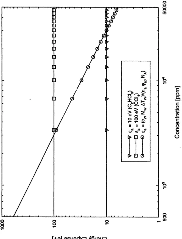
At a destruction and removal efficiency of higher than 99%, the energy expense for CC4 C'old Plasma Decomposition in dry air was found to be less than 1.50 eV per
CC14 molecule decomposed or 2.5 kWh/kg of CC4 decomposed. These values were
found to apply independently of the CC4 intake concentration.
Therefore, the C'old Plasma Decomposition of CC in a Tunable Plasma Reactor may be achieved at substantially lower operational cost than the customary Flame
Decomposition, which. at a CC4 intake concentration of lower than 500 ppm, requires
more than approximately 600 eV or 100 kWh/kg, respectively.
Thesis Supervisor Dr. Daniel R. Cohn, Ph.D.
Title Acting Assistant Director and Head, Plasma Technology and Systems Division, MIT Plasma Fusion Center
Acknowledgements
Most any individual embarking on an endeavor such as the pursuit of a doctorate degree from the venerable .1assachusetts Institute of Technology is bound to reach many points of utter despair and strong desire for surrender. Without the support of so many people. there would very likely be only one such point.
So here are thanks to a few of the people who helped me continue on whenever I reached those points. The list of all the people who supported me in my endeavor at one time or another would certainly fill an entire book.
I wish to express my gratitude to Dr. Daniel R. Cohn for his never-waning encour-agement and personal and financial support and particularly his guidance throughout the entire writing phase of this thesis. Without sharing with me his sure-footed gift to bring matters -to the point". I would probably still be writing on this thesis on page 1965 or so.
My gratitude is also directed to Dr. Richard M. Patrick. Although we had many arguments over the years, he helped me realize more than anyone else that life. even in the Iory Tower of Research, is anything but perfect and that one has to risk making enemies in order to advance one's own ideas. Thanks also for reading much of this thesis.
My special gratitude goes to Prof. Mujid S. Kazimi, whom I have known for four and a half years now and who in all these years never failed to amaze me with the sharpness of his intellect and the correctness of his judgement. Some people just
"have it".
I would also like to express my gratitude to Prof. Hermann H. Unger, who, as my professor back in "Good (or is it Bad) Old Germany", I firmly believe bears the primary responsibility for the fact that I find myself in the (lucky?) position that I am in today (Send SAE to author for details).
Thanks go to Dr. Steven M. Royce of the Hewlett-Packard Company and to Ron P. Kensek of the Sandia National Laboratory for enlightening me on what exactly a Gas Clromatograph and a Mass Spectrometer represent and on what precisely a
Monte-Carlo Simulation has to do with electron beam power deposition.
Thanks also go to Mr. Paul Thomas for creating Frankenstein's Monster, or as he calls it, "The Beam". and to Mr. Paul Falkos for taming the monster, although a
And this one goes to Mr. Matthew P. Schuetze! Sir. you deserve my deepest respect for your decision to leave it (for now) at the ALS. degree. It would surely be an utter waste of your multi-faceted talents to have you "do time" for a Ph.D. degree.
And let us not forget the good spirits of Ms. Janet K. Anderson and Mr. (soon to be Dr.) Kenneth Mitchell Crosswait. I never quite understood how one could permanently maintain a positive attitude to "all of this", but these two people manage to - a truly amazing feat! To cast it in the words of my favorite Southern Rock band,
they always -pick me up when I'm feelin' blue*
Well. and then there are Dr. Leslie -Chip- Bromberg and Dr. Milan -Dale" Tekula - two men that could be trusted more I have never known. Without their constant encouragement and optimism. as epitomized by the evergreen "How are you doing? I don't know! The only thing I know is. I am doing worse than yesterday and better than tomorrow!". this thesis would have been unbearably enjoyable. Thanks. -Chip 'N Dale", for the countless -New England Seafood Chowder Dinners- you treated me to over the past years.
Finally, although it may sound as though I have left the realm of mental sanity completely now (which is probably not far from the truth for those who know me), I feel the urge to thank my 1986 Oldsmobile Cutlass Supreme Brougham. a finer
A utomobile I have never driven. With it, I could (and in fact do) drive circles around
any contemporary German or Japanese
Car
any time. Twenty miles to the gallon and built like a tank - were have all the good times gone?Vell. the race is almost over now, soon I'll be cooling the engine. It's been running reliably, although the RPMs have been in the red almost permanently. It's been fun at times, but not even a Mercedes-Benz can do it for ever. Gotta learn how to drive in the green now or I will be worn out to pieces by the time I hit the thirties.
Contents
1 Introduction
1.1 Introduction . . . . 1.2 Background . . . . 1.2.1 Environmental Pollution and Hazardous Waste . 1.2.2 Context of Present Work . . . . 1.3 M otivation . . . . 1.4 O bjective . . . . 1.4.1 Tunable Plasma Reactor . . . . 1.4.2 Hazardous Chemical Compounds . . . ...
1.5 O verview . . . . 1.5.1 Organization of Present Work . . . . 1.5.2 New Aspects of Present Work . . . .
2 Background
2.1 Introduction to Cold Plasma Decomposition . . . . 2.1.1 General Remarks . . . . 2.1.2 The Difference Between A Flame and A Plasma . . . . 2.1.3 The Difference Between A Hot Plasma and A Cold Plasma . . 2.1.4 The Generation of A Cold Plasma . . . .
25 . . . . 25 . . . . 2 7 . . . . 2 7 . . . . 28 . . . . 29 . . . . 30 . . . . 30 . . . . 3 1 . . . . 33 . . . . 33 . . . . 34 36 36 36 36 37 38
2.1.5 The Shotgun and The Rifle . . . . 2.1.6 Review of Current Research in Cold Plasma Dec 2.2 Energy Expense . . . . 2.3 Chemical Species and Chemical Reactions . . . . 2.3.1 Chemical Species . . . . 2.3.2 Chemical Reactions . . . . 2.4 Chemical Kinetics . . . . 2.4.1 General Considerations . . . . 2.4.2 Reactants and Products . . . . 2.4.3 Reaction Rate Constants . . . . 2.4.4 Concentration of Chemical Species . . . . 2.4.5 Example for Chemical Kinetics . . . . 2.5 G -Value . . . . 2.5.1 Definition of G-Value . . . . 2.5.2 G-Value in Chemical Dosimetry . . . . 2.5.3 G-Value in Chemical Kinetics . . . . 2.5.4 G-Value in Destruction and Removal Efficiency 2.5.5 G-Value in Energy Expense . . . .
omposition
2.6 Typical Parameters of Electron Beam Generated Cold Plasma . . . . 2.6.1 General Considerations . . . . 2.6.2 G-Value for Production of Electrons and Atomic Oxygen Radicals 2.6.3 Electrons in Recombination Controlled Cold Plasma . . . . 2.6.4 Electrons in Attachment Controlled Cold Plasma . . . . 2.6.5 Negative Ions in Attachment Controlled Cold Plasma . . . . .
40 41 . . . . 42 . . . . 46 . . . . 46 . . . . 46 . . . . 50 . . . . 50 . . . . 50 . . . . 5 1 . . . . 52 . . . . 54 . . . . 55 . . . . 55 5 7 . . . . 58 . . . . 59 . . . . 60 62 62 62 63 64 64
2.6.6 2.6.7 2.6.8
Atomic Oxygen Radicals in Cold Plasma . . . . Importance of Diffusion to Chemical Reactions . . . . Importance of Residence Time to Chemical Reactions . . . . .
65 67 68
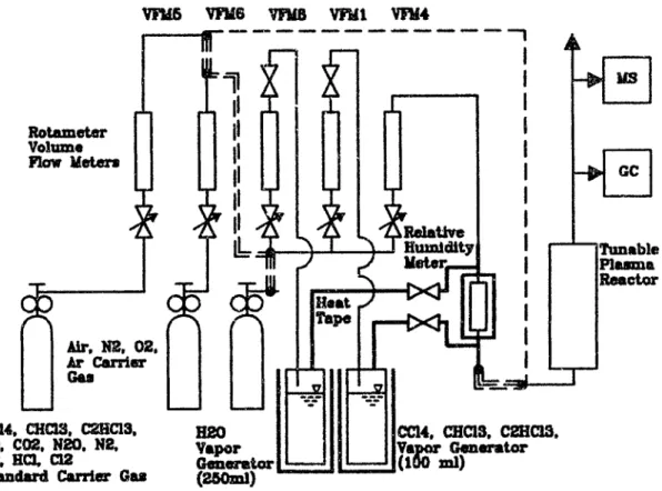
3 Gas Mixing System 69
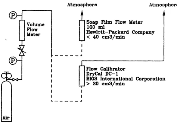
3.1 Introduction to Gas Mixing System . . . . 69
3.2 Description of Gas Mixing System . . . . 70
3.2.1 Volume Flow Meter Combinations . . . . 70
3.2.2 Vapor Generators . . . . ... . . . . 71
3.2.3 Tubing . . . . 72
3.2.4 Stainless Steel to Pyrex Glass Interface . . . . 73
3.3 Theory of Dynamic Gas Mixing . . . . 73
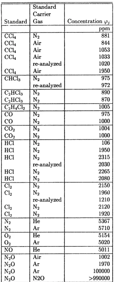
3.4 Static Generation of Standard Carrier Gases . . . . 75
3.5 Dynamic Generation of Standard Carrier Gases . . . . 77
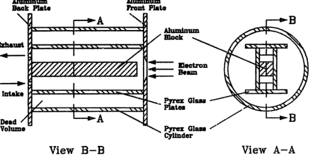
3.6 Calibration of Rotameter . . . . 80 4 Tunable Plasma Reactor
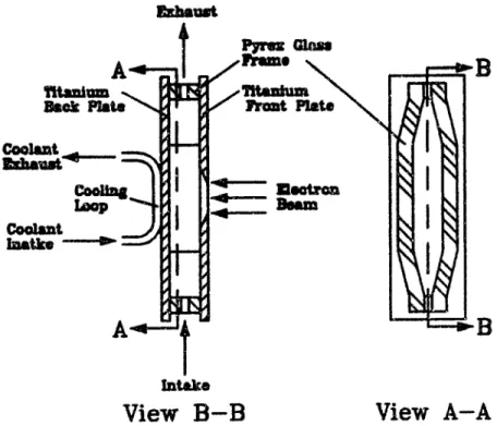
4.1 Components of Tunable Plasma Reactor . . . . 4.2 Reaction Chamber . . . . 4.2.1 Old vs. New Reaction Chamber . . . . 4.2.2 Old Reaction Chamber . . . . 4 2.3 New Reaction Chamber . . . . 4.3 Electron Beam . . . . 4.3.1 Fundamental Considerations . . . . . . . . 4.3.2 Electron Beam Generation . . . .
85 85 85 85 86 88 90 90 91
4.3.3 Electron Beam Acceleration . . . .9
4.3.4 Electron Beam Shaping and Electron Beam Current Control . 93 4.3.5 Richardson's Equation and Child's Equation . . . . 97
4.3.5.1 General Remarks . . . . 97
4.3.5.2 Richardson's Equation . . . . 98
4.3.5.3 Child's Equation . . . . 99
4.3.6 Electron Beam Generation and Acceleration Circuit . . . . 100
4.3.7 Electron Beam Gun Vacuum System . . . . 100
4.4 Electron Beam Window . . . . 103
4.4.1 Fundamental Considerations . . . . 103
4.4.2 Support Grid Geometry . . . . 106
4.4.2.1 Slot and Rib Areas . . . . 106
4.4.2.2 Transmission to Electron Beam . . . . 108
4.4.3 Thermal Load on Support Grid and Foil . . . . 109
4.4.3.1 Definition of Thermal Load . . . . 109
4.4.3.2 Maximum Support Grid Temperature . . . . 110
4.4.3.3 Maximum Foil Temperature . . . . 111
4.4.3.4 Maximum Support Grid and Foil Temperature . . . 112
4.4.4 Mechanical Load on Foil . . . . 112
4.4.4.1 Definition of Mechanical Load . . . . 112
4.4.4.2 Foil Tension Stress . . . . 112
4.4.4.3 Foil Shear Stress . . . . . . 113
4.4.5 Aluminum-Titanium Composite Foil . . . . 114
4.4.5.1 Advantage of Composite Foil . . . . 114 92
4.4.5.2 Modulus of Elasticity . . . . 114
4.4.5.3 Thermal Conductivity . . . . 115
4.5 Electric Field . . . . 116
5 Gas Analysis System 120 5.1 Introduction to Gas Analysis System . . . . 120
5.2 Gas Chromatograph and Gas Chromatograph
/
Mass Spectrometer . 122 5.2.1 Separative Analysis . . . . 1225.2.2 Sample Introduction System . . . . 124
5.2.2.1 Principle of Operation . . . . 124
5.2.2.2 Theory of Operation . . . . 125
5.2.2.3 Technical Considerations . . . . 127
5.2.3 Gas Chromatographic Columns . . . . 128
5.2.3.1 Principle of Operation . . . . 128
5.2.3.2 Theory of Operation . . . . 129
5.2.3.3 Technical Considerations . . . . 130
5.2.4 Gas Chromatographic Detectors . . . . 133
5.2.4.1 Types of Detectors . . . . 133
5.2.4.2 Sample Dilution . . . . 133
5.2.4.3 Concentration Dependent Detectors . . . . 134
5.2.4.4 Quantitation . . . . 135
5.2.5 Thermal Conductivity Detector . . . . 136
5.2.5.1 Principle of Operation . . . . 13G 5.2.5.2 Technical Considerations . . . . 137
5.2.6.1 Principle of Operation . . . .
5.2.6.2 Modes of Operation . . . . 5.2.7 Mass Selective Detector . . . .
5.2.7.1 Difference between TCD or ECD and MSD . . . . . 5.2.7.2 Gas Chromatograph-Mass Spectrometer Interface . . 5.2 7.3 Principle of Operation . . . . 14 2 5.2.Y.4 Theory of Operation . . . .
5.3 Mass Spectrometer . . . . 5.3.1 Non-Separative Analysis . . . . 5.3.2 SOR-MS Sample Introduction System . . . . 5.3.2.1 Principle of Operation . . . . 5.3.2.2 Theory of Operation . . . .
5.3.2.3 MSD Pressure Monitoring . . . . 5.3.3 SOR-MS Data Analysis . . . .
5.3.3.1 Principle of Operation . . . . 5.3.3.2 Technical Considerations . . . . 5.3.3.3 Theory of Operation . . . . 5.3.4 Potential and Limitations . . . . 5.3.4.1 Feasibility of Conversion . . . . 5.3.4.2 Tuning . . . . 5.3.4.3 Electron Multiplier Voltage . . . . 5.3.4.4 Pressure . . . . 5.3.4.5 Relative Humidity . . . . 5.3.4.6 Passivation . . . . 137 139 140 140 140 143 145 . . . 145 . . . 147 . . . 147 149 . 151 153 . . . 153 . . . 154 . . . 155 . . . 158 158 159 160 161 . . . 162 . . . 162
5.3.4.7 Selected Ion Monitoring vs. Full Scan Monitoring . . 5.3.4.8 Accuracy, Precision, Reproducibility and Detection
Lim it . . . . 5.3.4.9 Deconvolution. . . . . .5-3.5 Feasibility of GC-MS to SOR-MS Conversion of MSD . . . . . 6 Electron Beam Dosimetry
6.1 Introduction to Electron Beam Dosimetry . . . . 6.2 Facsimile Paper Radiography . . . . 6.2.1 Principle of Operation . . . . 6.2.2 Electron Beam Uniformity Over Electron Beam Cros A rea . . . . 6.2.3 Electron Beam Spreading Inside Electron Beam Gun
Cham ber . . . . 6.3 Aluminum Plate Calorimetry . . . . 6.3.1 Principle of Operation . . . . 6.3.2 Theory of Operation . . . . 6.3.3 Technical Considerations . . . . 6.4 6.5 S Sectioi Vacuun
6.3.4 One-Dimensional Monte-Carlo Simulation of Electron Beam Power Transmission Through Electron Beam Window . . . . . 6.3.5 Electron Beam Power Transmission Through Electron Beam
W indow . . . . Definition of Electron Beam Dose . . . .. One-Dimensional Monte-Carlo Dosimetry . . . . 6.5.1 Principle of Monte-Carlo Dosimetry . . . . 6.5.2 Principle of TIGER Code . . . . 6.5.3 Electron Beam Energy Loss of TIGER Code . . . .
I 163 163 164 165 166 166 167 167 168 169 172 172 173 175 176 177 178 180 180 181 182
6.5.4 6.5.5 6.5.6 6.5.7 6.5.8 6.5.9 6.6 Nitrou 6.6.1 6.6.2 6.6.3 6.6.4
Reflectivity and Transmissivity of TIGER Code . . . . Geometries of Simulated Cases . . . . Results of Simulated Cases . . . . Interpretation of Simulated Cases . . . . Electron Beam Power Deposition and Electron Beam Dose of Simulated Cases . . . . Electron Beam Stopping Power . . . . s Oxide Dosimetry . . . . Principle of Nitrous Oxide Dosimetry . . . . History of Nitrous Oxide Dosimetry . . . . Theory of Nitrous Oxide Dosimetry . . . . Results of Nitrous Oxide Dosimetry . . . . . . . .
7 Experimental Procedures and Results
7.1 General Considerations ... ...
7.2 Effect of Intake Concentration and Electron Beam Dose on CCl De-com position . . . . 7.3 Effect of Relative Humidity on CCL Decomposition . . . . 7.4 Effect of Air and Oxygen on CC Decomposition . . . . 7.5 Transition from Old Reaction Chamber to New Reaction Chamber. . 7.6 Effect of Electric Field on CC4 and CHC 3 Decomposition ...
7.7 Products and By-Products of CCL Decomposition . . . . 7.7.1 General Considerations . . . . 7.7.2 Measurement of CCL Decomposition Products CO and CO2
and CCL Decomposition By-Product N20 . . . .
7.7.3 Measurement of CC4 and CCL Decomposition Products COCl2,
C12 and HCl . . . . 183 184 187 192 195 196 199 199 199 201 202 207 207 210 212 214 217 217 227 227 229 229
7.8 Effect of Relative Humidity on C2HC13 Decomposition . . . . . . 241
7.9 Measurement of C2HCl3 and C2HC13 Decomposition Products C2HC130,
COCl2, Cl2 and HCl . . . . 243 7.10 Effect of Electric Field on C2HC13 Decomposition . . . . 248
8 Interpretation of Experimental Results
8.1 Scope of Interpretation . . . . 8.2 Qualitative Discussion of CC14 and CHC13 Decomposition . . . . . 8.2.1 CC4 and CHC13 Decomposition . . . .
8.2.2 Reaction Mechanism of CCL4 and CHCl3 Decomposition . 8.3 Electron Attachment Frequencies . . . . 8.3.1 General Considerations . . . . 8.3.2 02, CCLI, CHC13 and C2HCl3 . . . . 8.3.3 HCl, Cl2 and COCl2 . . . .
8.3.4 03, NO2 and N20 . . . . 8.3.5 H20 and HN03 . . . .. . . . . . . . .. . . . . . . .
8.4 Semi-Quantitative Discussion of CC14 Decomposition . . . . 8.4.1 General Considerations . . . . 8.4.2 Low CC4 Intake Concentration . . . . 8.4.3 High CC4 Intake Concentration . . . . 8.4.4 Heuristic Equation for CCL Decomposition
8.4.5 Heuristic Energy Expense for CCL4 Decomposition . 8.4.6 Heuristic Scaling Law for CC4 Decomposition . . .
8.5 Qualitative Discussion of C2HC13 Decomposition . . . .
8.5.1 C2HCl3 Decomposition . . . . 250 250 251 251 252 255 255 255 257 259 260 262 262 262 264 267 268 270 272 272
8.5.2 Reaction Mechanism of C2HC13 Decomposition . . . . 274
8.5.3 Reaction Mechanism of CIOC-CHC12 Decomposition . . . . . 277
8.5.4 Reaction Mechanism of CC13 and CHC2 Decomposition . . . 278
8.5.5 Reaction Mechanism of CC12 and CHCl Decomposition . . . . 279
8.6 Comparison of Cold Plasma Energy Expense . . . . 279
9 Summary and Conclusion 281 9.1 Summary ... ... 281
9.2 Conclusion ... . 283
9.3 Recommendations for Future Work ... ... 287
9.3.1 General Remarks . . . . 287
9.3.2 Experiments . . . . 288
9.3.3 Experimental Equipment . . . . 290
9.4 Overall Perspective for Tunable Plasma Reactor . . . . 291
A Appendix to Chapter 1 311 A.1 Naming Convention for Chlorinated Methanes and Ethenes . . . . 311
A.2 Scientific and Engineering Constants . . . . 312
A.3 General Solution to Differential Equation, Part One . . . . 312
A.4 General Solution to Differential Equation, Part Two . . . . 314
B Appendix to Chapter 3 316 B.1 Vapor Pressure of Pure Liquid . . . . 316
B.2 Rotameter Calibration . . . . 319
B.3 Theory of Rotameter Operation . . . . 319
C.1 C.2 C.3 C.4
Child's Equation . . . . One-Dimensional Temperature Distribution . . . . Foil Tension Stress . . . . Foil Shear Stress . . . .
D Appendix to Chapter 5
D.1 Plate Theory of Gas Chromatographic Separation D.2 Gauss Theory of Gas Chromatographic Separation. D.3 Theory of Thermal Conductivity Detector Operation D.4 Theory of Electron Capture Detector Operation .
D.4.1 Non-Sensitized Electron Capture Detector D.4.2 Sensitized Electron Capture Detector...
D.4.2.0.1 N20 Sensitization . . . .
D.4.2.0.2 02 Sensitization . . . . ..
D.5 Mathieu Theory of Mass Filtering . . . ..
E Appendix to Chapter 6
E.1 Conversion of R to rad as the Dimension of the Dose . . . . . . . . 359 359 . . . . 326 . . . . 329 . . . . 330 . . . . 335 338 . . . 338 . . . . 341 . . . . 346 . . . . 347 . . . . 347 . . . 350 . . . . 351 . . . . 351 . . . . . . 352 .
List of Figures
1.1 Chemical Structure of Hazardous Chemical Compounds . . . . 2.1 Energy Expense for Flame Decomposition and Cold Plasma
Decom-position . . . . 2.2 Bimolecular Dissociative Electron Attachment Reaction Rate Constant
for CC14 , CHC3 and C2HC13, adapted from [32] and [69] . . . .
3.1 Variations of Gas Mixing System . . . . 3.2 Volume Flow Meter Calibration . . . . 4.1 Old Reaction Chamber . . . .
4.2 New Reaction Chamber . . . . 4.3 Triode Electron Beam Gun Design 4.4 Effective Triode Voltage Distribution 4.5 Electron Beam Generation Circuit . . . 4.6 Electron Beam Acceleration Circuit . . 4.7 Support Grid Geometry . . . .
. . . . 87 . . . . 89 . . . . 94 . . . . 95 . . . . 101 . . . . 102 . . . . 107 4.8 Average Electron Energy as Function of Reduced Electric Field, adapted
from [32], [74] and [93 . . . .
Automatic Sample Introduction System ...
SOR-MS Sample Introduction System . . . . 118 125 148 32 45 49 71 84 5.1 5.2
6.1 Electron Beam Uniformity Over Electron Beam Cross Section Area,
E0 110 keV, Io 1.0 mA, t ; 100 ms . . . . 168
6.2 Electron Beam Spreading Inside Electron Beam Gun Vacuum Cham-ber, Eo ; 110 keV, Io ; 1.0 mA, t z 100 ms . . . . 170 6.3 Relations Among Areas and Electron Beam Currents for Analysis of
Electron Beam Spreading Inside Electron Beam Gun Vacuum Chamber 171 6.4 Electron Beam Energy Loss in Air and N20 at Various Electron Beam
Energies, First Case . . . . 188 6.5 Electron Beam Energy Loss in 02, N2 and Ar at Various Electron Beam
Energies, Second Case . . . . 189 6.6 Electron Beam Energy Loss in Air at Various Gas Temperatures, Foil
Material Aluminum. Third Case . . . . 190 6.7 Electron Beam Energy Loss in N20 at Various Gas Temperatures, Foil
Material Aluminum, Third Case . . . . 191 6.8 Electron Beam Energy Loss in Air at Various Gas Temperatures, Foil
Material Aluminum/Titanium Composite, Fourth Case . . . . 193 6.9 Electron Beam Energy Loss in N20 at Various Gas Temperatures, Foil
Material Aluminum/Titanium Composite, Fourth Case . . . . 194 6.10 N2 Concentration vs. Ratio of Electron Beam Current to Mass Flow
Rate of N20 for N20 Dosimetry . . . . 204
7.1 Effect of Intake Concentration and Electron Beam Dose on CC De-composition in Dry Air . . . . 211 7.2 Effect of Relative Humidity on CC4 Decomposition in 20 %RH Wet Air213
7.3 Effect of Air and Oxygen on CC4 Decomposition in Dry Air and
Oxy-gen and 12.5 %RH WNet Air and OxyOxy-gen, Old Reaction Chamber . . . 216 7.4 Effect of Air and Oxygen on CC14 Decomposition in Dry Air and
Oxy-gen and 12.5%RH Wet Air and OxyOxy-gen, New Reaction Chamber . . . 218 7.5 Effect of Air and Oxygen on CC14 Decomposition in Dry Air and
Oxy-gen, Old vs. New Reaction Chamber . . . . 219 7.6 Effect of Electric Field on CC4 Decomposition in Dry Air . . . . 221
7.7 Effect of Electric Field on CHC13 Decomposition in Dry Air . . . . . 222 7.8 Effect of Electric Field on CCL4 Decomposition in 12 %RH Vet Air . 223
7.9 Effect of Electric Field on CHC3 Decomposition in 11 %RH Wet Air 224 7.10 Effect of Electron Beam Dose on CCL and CHCl3 Decomposition in
Dry Air and in 11 %RH and 12 %RH Wet Air . . . . 226 7.11 CCL Decomposition Products and By-Products CO, CO2 and N20 in
Dry Air for 278 ppm CC14 Intake Concentration . . . . 230
7.12 CC14 Decomposition Products and By-Products CO, CO2 and N20 in
9 %RH Wet Air for 105 ppm CC4 Intake Concentration . . . . 231 7.13 CC14 Decomposition Products and By-Products CO, CO2 and N20 in
11 %RH Wet Air for 224 ppm CCL Intake Concentration . . . . 232 7.14 CCL Decomposition Products CO and CO2 in Dry Air for 125 ppm
CC4 Intake Concentration . . . . 233 7.15 CCL Decomposition Products CO and CO2 in 10 %RH Wet Air for
142 ppm CC14 Intake Concentration . . . . 234 7.16 CC14 Decomposition Products HCI, Cl2 and COC12 in Dry Air for
278 ppm CC14 Intake Concentration . . . . 236 7.17 CCLI Decomposition Products HCI, Cl2 and COC12 in 9 %RH Wet Air
for 105 ppm CC14 Intake Concentration . . . . 237 7.18 CCL Decomposition Products HCl, Cl2 and COC2 in 11 %RH Wet
Air for 224 ppm CCL Intake Concentration . . . . 238 7.19 Effect of Relative Humidity on C2HC13 Decomposition in Dry Air for
517 ppm C2HCl3 Intake Concentration and in 11 %RH Wet Air for
490 ppm C2HC13 Intake Concentration . . . . 242 7.20 C2HC 3 Decomposition Products HCI, Cl2, COC12 and C2HC130 in
Dry Air for 517 ppm C2HC3 Intake Concentration . . . . 245 7.21 C2HCl3 Decomposition Products HCl, Cl2, COC12 and C2HC130 in 11
%RH Wet Air for 490 ppm C2HC 3 Intake Concentration . . . . 246 7.22 Effect of Electric Field on C2HCl3 Decomposition in Dry Air . . . . . 249
8.2 Heuristic CCL4 Exhaust Concentration Approximation . . . . . . 269 8.3 Heuristic CCL4 Energy Expense Approximation . . . . 271 8.4 Chemical Structure of Chemical Species in C2HC 3 Decomposition . . 275
C.1 Foil Tension Stress Force Balance . . . . 331 C.2 Foil Shear Stress Force Balance . . . . 336
List of Tables
2.1 Product of Number Densities and Electron Diffusion Coefficients [74] 67
2.2 Positive Ion and Negative Ion Diffusion Coefficients [74] . . . . . . 67
3.1 Standards and Standard Carrier Gases . . . . 78 3.2 Mole Masses of Standards and Standard Carrier Gases. adapted from
[83] . . . .. . . .. 79 3.3 Mole Mass M1 , Melting Temperature Tmj, Boiling Temperature TbI,
Liquid Mass Density pj, Fitting Parameters Tj and p) and Heat of Vaporization Ahe, for Hazardous Chemical Compounds and Water, adapted from [84] . . . . 80 3.4 Ratio of Vapor Pressure pj(T) to 760 torr at Various Temperatures T
for Hazardous Chemical Compounds and Water, adapted from [84] . 81 3.5 Volume Flow Meters . . . . 83 3.6 Volume Flow Meter Calibrations . . . . 83 4.1 Commonly Used Parameter Sets for Richardson's Law [91] . . . . 99 4.2 Electron Current Densities for Commonly Used Parameter Sets for
Richardson's Equation . . . . 99 5.1 Capillary Columns . . . . 132 5.2 Thermal Conductivities of Chemical Compounds, adapted from [84] . 138 5.3 Mole Masses M., and Kinematic Viscosities r., of Various Gases, adapted
5.4 Ion Gauge Pressure Correction Factors [129] . . . . 152 5.5 Chemical Compounds and Quant Ions . . . . 154 6.1 Results of Aluminum Plate Calorimetry . . . . 178 6.2 1-D Monte-Carlo Simulation, First Case . . . . 185 6.3 1-D Monte-Carlo Simulation, Second Case . . . . 185 6.4 1-D Monte-Carlo Simulation, Third Case . . . . 186 6.5 1-D Monte-Carlo Simulation, Fourth Case . . . . 186 6.6 Air Volume and Mass Flow Rates . . . . 195 6.7 Electron Beam Power Deposition and Electron Beam Dose in Air . . 196 6.8 N20 Volume and Mass Flow Rates for N20 Dosimetry . . . . 202
6.9 N2 Concentration pN2 in N20 in ppm for N20 Dosimetry . . . . 203
6.10 Electron Beam Dose DN2o in N20 in Mrad for N20 Dosimetry . . . 205
6.11 Electron Beam Power Deposition QN2O in N20 in W for N20 Dosimetry205
6.12 Electron Beam Power Deposition QAi in Air in W for N20 Dosimetry 205
8.1 Comparison of Cold Piasma Energy Expense for CC4 Decomposition
at 99 % Destruction and Removal Efficiency . . . . 280 8.2 Comparison of Cold Plasma Energy Expense for C2HC13
Decomposi-tion at 99 % DestrucDecomposi-tion and Removal Efficiency . . . . 280 A.1 Chemical Formulas for Halogenated Methanes, Ethanes and Ethenes . 311 A.2 Scientific and Engineering Constantt (83] . . . . 312
B.1 Volume Flow Meter 1: Omega FL-220 (No.1) (Glass Float) . . . . 319 B.2 Volume Flow Meter 2: Omega FL-220 (No.2) (Glass Float) . . . . 320 B.3 Volume Flow Meter 3: Omega FL-221 (Glass Float) . . . . 320 B.4 Volume Flow Meter 4: Omega FL-224 (Glass Float) . . . . 321
B.5 Volume Flow Meter 5: Matheson E603 (Glass Float) . . . . 321 B.6 Volume Flow Meter 6: Matheson E605 (Glass Float) . . . . 322 B.7 Volume Flow Meter 7: Dwyer (No.1) (Glass Float) . . . . 322 B.8 Volume Flow Meter 8: Dwyer (No.2) (Glass Float) . . . . 323 D.1 Masses in Gas Phase and Liquid Phase for First Five Plates and First
Five Plate Residence Times of Gas Chromatographic Separation Ac-cording to Plate Theory . . . . 341 D.2 Relative Sensitivities of Electron Capture Detector [97] . . . . 350
Chapter 1
Introduction
1.1
Introduction
The compliance with a large number of regulatory acts concerning environmental pol-lution requires improved polpol-lution remediation and polpol-lution control through treat-ment of hazardous waste [1).
A major fraction of this waste is solid and liquid hazardous waste, while only a minor fraction is gaseous hazardous waste. However, a major fraction of the solid and liquid hazardous waste is converted into gaseous hazardous waste through treatment. In particular, much of this gaseous hazardous waste contains low concentrations of hazardous chemical compounds and high concentrations of air.
The objective of the treatment of such gaseous hazardous waste is the decomposi-tion of hazardous chemical compounds into less hazardous or non-hazardous decom-position products. The decomdecom-position is to be achieved with a minimum of energy, decomposition by-products and secondary waste per amount of hazardous chemical compound decomposed.
A number of approaches to treatment of gaseous hazardous waste exist [2]. The conventional approach is the decomposition of hazardous chemical compounds in a flame at atmospheric pressure [3]. One of the unconventional approaches is the decomposition of hazardous chemical compounds in a cold plasma at atmospheric pressure.
A flame is unselective in that the amount of energy required for the treatment of gaseous hazardous waste is independent of the concentrations of the hazardous chemical compounds. A cold plasma is selective in that the amount of energy required for the treatment of the gaseous hazardous waste is dependent on the concentrations
of the hazardous chemical compounds.
Therefore, while the decomposition in a flame may be efficient at high concentra-tions, the decomposition in a cold plasma may be efficient at low concentrations. This difference may be likened to the difference between a shotgun and a rifle. The shotgun takes out many targets unselectively while the rifle takes out few targets selectively. In a very simplistic perspective, a cold plasma is distinguished from a flame through a higher concentration of electrons and a higher concentration of radicals. Therefore, a cold plasma may be especially suitable for decomposition of hazardous chemical compounds for which dissociative electron attachment or radical attack initiate the decomposition.
The present work focuses on the investigation of cold plasma decomposition of hazardous chemical compounds by dissociative electron attachment and radical at-tack. The halogenated methanes and ethenes, a subset of aliphatic organic hazardous chemical compounds. are selected for the investigation.
On the basis of the high electron affinity of halogenated chemical compounds in general and the absence of a fragile carbon double bond, dissociative electron attach-ment may be expected to initiate the decomposition of halogenated methanes. On the basis of the presence of a fragile carbon double bond, radical attack may be expected to initiate the decomposition of halogenated ethenes.
A number of approaches to the generation of a cold plasma exist. However, because of the inherently high rate of generation of electrons and the inherently high rate of generation of radicals, generation of a cold plasma by an energetic electron beam is of particular interest.
Moreover, dissociative electron attachment is expected to be dependent on the average electron energy. Therefore, an electric field may be superimposed to the electron beam so that the electron concentration and the radical concentration are controlled by the electron beam current and the average electron energy is controlled by the electric field voltage.
Individually, dissociative electron attachment, radical attack, generation of a cold plasma by an energetic electron beam and electric fields are well known. However, their integration into a plasma chemical reactor for decomposition of hazardous chem-ical compounds has received relatively little attention [4] and therefore represents a major contribution of the present work. The superposition of the electron beam and the electric field gives rise to the name Tunable Plasma Reactor (TPR) for such a plasma chemical reactor.
par-ticularities of decomposition of halogenated methanes and ethenes and the demon-stration of the potential usefulness of the Tunable Plasma Reactor for decomposition of halogenated methanes and ethenes represent a significant outcome of the present work.
An important part of the qualitative and semi-quantitative understanding is the difference between initiation of decomposition via dissociative electron attachment and initiation of decomposition via radical attack.
Moreover, as a classical example of the applied sciences, the investigation of the de-composition of above hazardous chemical compounds in the Tunable Plasma Reactor on a laboratory scale allows for the implementation of this reactor on a field scale.
1.2
Background
1.2.1 Environmental Pollution and Hazardous Waste
Over the past few decades, concerns over Environmental Pollution have precipitated in a large number of regulatory acts devised to restore the environment through
Pollution Remediation and to protect the environment through Pollution Control
and Pollution Prevention. The more prominent of these regulatory acts are the Clean
Air Act (CAA), the Comprehensive Environmental Responsibility and Compliance Liability Act (CERCLA) and the Resource Conservation and Recovery Act (RCRA)
[5].
In general terms. environmental pollution may be defined as the contamination of the lithosphere, hydrosphere or atmosphere through hazardous chemical compounds resulting for example in contaminated soil, water and air. The hazardous chemical compounds are contained in solid, liquid or gaseous hazardous waste entering the three spheres.
The hazard associated with hazardous waste is a function of the concenwrations of hazardous chemical compounds in such waste and of the hazard associated with these chemical compounds. According to the Environmental Protection Agency (EPA) Chapter 40 Code of Fedeml Regulations Part 261 (EPA 40 CFR 261), solid, liquid or gaseous hazardous waste may be classified on the basis of hazard codes [6].
The hazardous chemical compounds in hazardous waste may represent virtually the entire spectrum of chemical compounds known to mankind. In particular, the molecules of these chemical compounds may contain virtually the entire spectrum of elements known to mankind.
The contamination of the lithosphere, hydrosphere or atmosphere is tolerable below. and intolerable above, certain concentrations of hazardous chemical compounds in the three spheres. Such concentration may be referred to as the Contamination Tolerance
Threshold.
The intent of pollution remediation is to reduce the concentrations of hazardous chemical compounds in the lithosphere, hydrosphere or atmosphere to or below the contamination tolerance threshold through treatment of contaminated soil, water or air.
The purpose of pollution control is to maintain the concentrations of hazardous chemical compounds in the lithosphere, hydrosphere and atmosphere at or below the contamination tolerance threshold through treatment of solid, liquid or gaseous hazardous waste entering the three spheres.
The objective of pollution prevention is to reduce the solid, liquid or gaseous haz-ardous waste entering the lithosphere, hydrosphere or atmosphere altogether.
Frequently, pollution control requires the decomposition of hazardous chemical com-pounds in hazardous waste into less hazardous or non-hazardous chemical comcom-pounds. In addition to the generation of such less hazardous or non-hazardous decomposi-tion products, generadecomposi-tion of hazardous or non-hazardous decomposidecomposi-tion by-products as well as secondary hazardous waste may take place during treatment of primary hazardous waste. Such generation depends on the technical particularities of pollution control technology.
Therefore, the decomposition is to be achieved with a minimum of energy, decompo-sition by-products and secondary waste per amount of hazardous chemical compound decomposed.
1.2.2
Context of Present Work
The present work is concerned with pollution control through treatment of gaseous hazardous waste entering the atmosphere. Of the hazard codes listed in EPA 40 CFR 261. only Hazard Code T is of interest to the present work. This hazard code represents (gaseous) hazardous waste for which the hazard is associated with, the
carcinogenic, mutagenic and/or teratogenic toxicity of the hazardous chemical
com-pounds.
hazardous waste represent halogenated aliphatic 1 organic chemical compounds. The molecules of these chemical compounds only contain the elements Hydrogen (H),
Carbon (C), Fluorine (F), Bromine (Br) and/or Chlorine (Cl).
The desired decomposition products are Water (H20), Carbon Monoxide (CO),
Carbon Dioxide (C0 2), Fluorine (F2), Chlorine (Cl2), Bromine (Br2), Hydrogen Flu-oride (HF), Hydrogen ChlFlu-oride (HC) and Hydrogen Bromide (HBr). The latter six
chemical compounds may be converted into non-hazardous salts through chemical re-action with Sodium Hydroxide (NaOH), Potassium Hydroxide (KOH) or other chem-ical compounds of the Alkali Metals.
The gaseous hazardous waste considered here is generated as secondary waste in pollution remediation such as Vapor Extraction, Air Stripping and Activated Charcoal
Adsorption/Desorption. Such gaseous hazardous waste is also generated as off gas
in industrial processes such as Semiconductor Manufacturing, Chemical Compound
Manufacturing, Dry Cleaning and Spray and Brush Painting.
1.3
Motivation
At the US Department of Energy's (USDoE) Hanford Site in Washington state, large quantities of the industrial solvent Carbon Tetrachloride (CC4) were used and sub-sequently disposed of in the soil below the site via Leaching Fields [7], [8].
The CC14 now threatens to migrate from the soil into the groundwater below the site. Such migration and the subsequent migration of the CCI into the nearby
Columbia River is to be prevented since CC4 is a suspected human teratogen and
carcinogen [9], [10], [11].
Efforts under USDoE's Volatile Organic Compound - Arid Integrated Demonstration Program (VOC-Arid-ID) are directed at Vapor Extraction of the CCI from the soil
[8], [12], [13].
At the very least, the air stream resulting from this process is c.s.;ected to con-tain high concentrations of Water (H20) and low concentrations of CCI. Owing to the hazard associated with the latter chemical compound, this air stream represents gaseous hazardous waste. In response to an ever eroding acceptance level for Flame
Decomposition of hazardous waste [14], [15], the decomposition of CCI in above
gaseous hazardous waste is to be accomplished without such flame decomposition.
1In
aliphatic organic chemical compounds, the elements are arranged in "lines", while in aromatic organic chemical compounds, the elements _e arranged in "circles".
Funding has been made available to the MIT-Plasma Fusion Center (PFC) in order to develop a plasma chemical reactor for Cold Plasma Decomposition that can perform this decomposition with a minimum of energy, decomposition by-products and secondary waste per amount of CC4 decomposed.
The CCL4 is to be decomposed into chemical compounds that do not require fur-ther treatment, such as Carbon Monoxide (CO) and Carbon Dioxide (C0 2), or that
require very little further treatment, such as conversion of Hydrogen Chloride (HCI) and Chlorine (Cl2) into Sodium Chloride (NaCl) via reaction with Sodium Hydroxide
(NaOH).
Moreover, the development of the plasma chemical reactor is to be performed with the intent of application not only to the decomposition of CC4, but also to the decomposition of other hazardous chemical compounds, such as Trichloro Ethylene (C2HC13), which are commonly found at USDoE, US Department of Defense (USDoD)
and non-government sites.
1.4
Objective
1.4.1
Tunable Plasma Reactor
The objective of the present work is the experimental investigation of the decompo-sition of hazardous chemical compounds in gaseous hazardous waste through Cold
Plasma Decomposition at atmospheric pressure.
This objective requires several tasks, including the design, construction and opera-tion of a Gas Mixing System for simulaopera-tion of the gaseous hazardous waste, a Tunable
Plasma Reactor (TPR) for decomposition of the hazardous chemical compounds and a Gas Analysis System for chemical analysis of the concentrations of the hazardous
chemical compounds as well as the decomposition products and decomposition by-products.
In the Tunable Plasma Reactor, the cold plasma at atmospheric pressure is gener-ated by an energetic electron beam, while an electric field may be applied across the plasma. An atmospheric pressure cold plasma allows for higher gaseous hazardous waste mass flow rates than a sub-atmospheric pressure cold plasma.
The electron concentration and the average electron energy in such a plasma may be controlled independently via the electron beam current and the electric field voltage, respectively. Moreover, the electron and/or radical concentration may be controlled through the addition of "promoters" to the gaseous hazardous waste. Such
"promot-ers" are chemical compounds that easily ionize or easily dissociate into radicals. The combination of electron beam current, electric field and "promoters" represents the
"tunability" of the Tunable Plasma Reactor.
The advantages of Cold Plasma Decomposition in the Tunable Plasma Reactorover
Flame Decomposition are expected to be a reduced energy consumption and less
haz-ardous or non-hazhaz-ardous decomposition products as well as a reduced amount of decomposition by-products and less secondary waste per amount of hazardous chem-ical compound decomposed. Moreover, better controllability of the decomposition through "tunability" and easier scalability to smaller units through use of electricity are expected.
In order to meet the objective and to prove or disprove some of these expected advantages, determination - to the extent possible - of the energy, the decompo-sition products, the decompodecompo-sition by-products and the secondary waste per amount of hazardous chemical compound decomposed is required.
Moreover, the chemical reactions that effect the decomposition of hazardous chem-ical compounds in gaseous hazardous waste are to be identified and/or ascertained - to the extent possible. The present work then provides a a basis for evaluation of the feasibility of the decomposition of hazardous chemical compounds in gaseous hazardous waste through Cold Plasma Decomposition in a Tunable Plasma Reactor.
1.4.2
Hazardous Chemical Compounds
As indicated earlier, the hazardous chemical compounds of interest in the present work are halogenated methanes and ethenes, which are derived from non-halogenated methane (CH4) and ethene (C2H4) via halogenation, i.e. substitution of Hydrogen (H)
by Fluorine (F), Chlorine (Cl), Bromine (Br) and/or Iodine (I).
The investigation of the decomposition of hazardous chemical compounds in gaseous hazardous waste through Cold Plasma Decomposition in a Tunable Plasma Reactor focuses on Tetrachloro Methane (Carbon Tetrachloride), a chlorinated methane with the chemical formula CC14, Trichloro Methane (Chloroform), a chlorinated methane
with the chemical formula CHCI3, and Trichloro Ethene (Trichloroethylene), a
chlo-rinated ethene with the chemical formula C21C13.
The chemical structure of these hazardous chemical compounds is shown in Fig-ure 1.1. Moreover, as a supplement, the naming convention for chlorinated methanes and ethenes is discussed in Appendix A.1.
ter-Cl
I
cl -c-c'
I
Cl
Cl-C-H
I
Cl
CI
Tetrachloro Methane
Trichloro Methane
Cl\
/H
Cl/C-C\Cl
Trichloro Ethene
atogens [9], [10], [11] and are found frequently in gaseous hazardous waste. However, on the basis of the motivation of the present work, the main emphasis of the investi-gation is placed on CCL1.
1.5
Overview
1.5.1
Organization of Present Work
The First Chapter provides, besides this Overview of the present work, the
Introduc-tion, the Background, the Motivation and the Objective of the present work, i.e. the
decomposition of hazardous chemical compounds in gaseous hazardous waste through
Cold Plasma Decomposition in a Tunable Plasma Reactor.
The Second Chapter describes the scientific background of the present work. The description includes the comparison of Flame, Cold Plasma and Hot Plasma, the projection of the Energy Expense per amount of hazardous chemical compound de-composed for Flame Decomposition and Cold Plasma Decomposition, the discussion of the Chemical Species and Chemical Reactions of importance to radiation and plasma chemistry as well as the definition of the G- Value as a classical quantity in radiation and plasma chemistry.
The Third Chapter provides a description of the Gas Mixing System developed for generation of particular concentrations of hazardous chemical compounds in simulated gaseous hazardous waste. The description includes a discussion of Dynamic Gas
Mixing via Static or Dynamic sources of hazardous chemical compounds, such as Compressed Gas Cylinders or Vapor Generators, respectively, and a discussion of the
calibration of the Rotameter volume flow meters used in the present work.
The Fourth Chapter provides a description of the Tunable Plasma Reactordeveloped for decomposition of hazardous chemical compounds in simulated gaseous hazardous waste. The description includes the Reaction Chamber, the Electron Beam and the
Electric Field. The Electron Beam is generated by an Electron Beam Gun, whose
principal components are the Vacuum System, the Electron Generation, the Electron
Acceleration and the Vacuum-to-Atmosphere Interface.
The Fifth Chapter provides a description of the Gas Analysis System developed for the chemical analysis of hazardous chemical compounds in simulated gaseous hazardous waste and the chemical analysis of decomposition products as well as de-composition by-products. The description includes the Gas Chromatograph, the Gas
The Sixth Chapter provides a description of the Electron Beam Dosimetry developed for determination of the electron beam power deposition in simulated gaseous haz-ardous waste and therefore the energy per amount of hazhaz-ardous chemical compound decomposed. The description includes the Facsimile Paper Radiography. the
Alu-minum Plate Calorimetry, the Monte-Carlo Simulation of the electron beam power
deposition and the N20 Chemical Dosimetry, i.e. the decomposition of Nitrous Oxide (N20) into N2 and 02.
The Seventh Chapter provides a description of the Experimental Procedure along with a presentation of the Experimental Results of the investigation of the decompo-sition of the hazardous chemical compounds Tetrachloro Methane (CC4), Trichloro
Methane (CHCI3), and Trichloro Ethene (C2HC13) in gaseous hazardous waste through
Cold Plasma Decomposition in a Tunable Plasma Reactor.
The Eighth Chapter provides an Interpretation of the experimental results on the basis of the scientific background of the present work and on the basis of current literature pertinent to the present work. Particular emphasis is placed on electron chemistry and radical chemistry.
The Ninth Chapter provides the Summary and Conclusion of the present work and the Recommendations for future work.
Note that scientific and engineering constants used in the present work are listed in Appendix A.2 and solutions to differential equations used in the present work are listed in Appendix A.3 and Appendix A.4.
1.5.2
New Aspects of Present Work
The major new contributions of the present work to the decomposition of hazardous chemical compounds in gaseous hazardous waste through Cold Plasma Decomposition are as follows:
1. A comprehensive and contrasting investigation of the decomposition of CC14,
CHCl3 and C2HC13 through Cold Plasma Decomposition in a Tunable Plasma
Reactor via chemical analysis of the reactor intake and reactor exhaust through Gas Chromatography, Gas Chromatography/Mass Spectrometry and Mass Spec-trometry has not been performed prior to the present work.
A number of investigations of cold plasma decomposition of halogenated methanes and ethenes are performed in parallel to the present work at other institutions
However, these investigations show relatively little attention to the decompo-sition of halogenated methanes and ethenes in a cold plasma generated by an energetic electron beam and only the first one and the last two of the referenced investigations employ such a cold plasma at all.
2. The superposition of an electron beam and an electric field to establish indepen-dent control of the elect -on concentration and the average electron energy of the cold plasma represents a technology transfer from the field of laser machining to the field of air pollution control
[26].
3. The combination of Facsimile Paper Radiogmphy, Aluminum Plate Calorimetry,
Monte-Carlo Simulation of electron beam power deposition and N20 Chemical
Dosimetry represents an innovative approach to electron beam dosimetry in gas. 4. The conversion of a Mass Selective Detector from a Gas Chromatogmphy/Mass
Spectrometry detector to a Stand-Alone, On-Line, Real-Time Mass Spectrome-try detector represents an innovative approach to utilization of such Mass Se-lective Detector.
Moreover, Hewlett-Packard Company, Palo Alto, California is currently investi-gating a similar conversion of their Mass Selective Detector in cooperation with
Tufts University, Cambridge, Massachusetts [27].
5. The interpretation of the experimental results of the decomposition of CC14,
CHC3 and C2HCI3 through Cold Plasma Decomposition in a Tunable Plasma
Reactor in terms of the integration of dissociative electron attachment and
rad-ical attack as well as the contrasting of the initiation of the decomposition via dissociative electron attachment and radical attack has not been performed prior to the present work. Moreover, the application of a modified G-Value to the semi-quantitative description of che decomposition of CC14 in dry air represents
Chapter 2
Background
2.1
Introduction to Cold Plasma Decomposition
2.1.1
General Remarks
A description of the scientific background of the present work is provided in the following. This very basic background comprises a qualitative discussion of Flame
Decomposition, Hot Plasma Decomposition and Cold Plasma Decomposition, a
quan-titative discussion of Chemical Species and their Chemical Reactions of importance to the radiation and plasma chemistry encountered in Cold Plasma Decomposition of hazardous chemical compounds through Electron Beam Generated Plasmas and a
quantitative discussion of the G- Value as a fundamental quantity in radiation and plasma chemistry.
2.1.2
The Difference Between A Flame and A Plasma
The decomposition of hazardous chemical compounds is usually effected through chemical reactions with Reactive Chemical Species. Frequently, these reactive chemi-cal species are electrons e- and radichemi-cals, such as the excited oxygen atoms O(sP) and O(1D), the hydroxyl molecule OH or the chlorine atom Cl.
Owing to their fast reaction rate constants, the concentration of these chemical species need not be very high in order to result in significant decomposition of the hazardous chemical compounds they react with.
has to contain other chemical species that can produce these reactive chemical species upon addition of the appropriate amount and form of energy to the gaseous hazardous waste. While e- may be produced from virtually any chemical species, O('P) and O(ID) may be produced from 02, OH may be produced from H20 or H20 2 and Cl
may be produced from chlorinated organic compounds.
In a Flame, the energy is provided in the form of thermal energy resulting in fast molecules which upon collision with appropriate other molecules generate above reactive chemical species. Such chemical reactions may be referred to as Thermally
Activated Chemical Reactions, since a high flame temperature is required.
In a Plasma. the energy is provided in the form of electric energy resulting in fast electrons which upon collision with appropriate other molecules generate above reac-tive chemical species. Such chemical reactions may be referred to as Non- Thermally
Activated Chemical Reactions, since a high plasma temperature is not required.
Since the reactive chemical species are typically generated by dissociative or non-dissociative electronic excitation or ionization, addition of energy in a form that favors such electronic excitation or ionization rather than translational, vibrational or rota-tional excitation should result in a more selective production of the reactive chemical species and therefore in a more selective decomposition of hazardous chemical com-pounds.
While such selectivity cannot be achieved in a flame due to unavoidable transla-tional, vibrational or rotational excitation, it can be achieved in a plasma. This may be explained heuristically by the fact that in a flame atoms or molecules must cause electronic excitation or ionization, while in a plasma electrons can cause such excita-tion or ionizaexcita-tion. Since electrons interact more efficiently with atomic or molecular electrons than atoms or molecules, they are more efficient in generating electronic excitation and ionization.
2.1.3
The Difference Between A Hot Plasma and A Cold
Plasma
The electric energy is commonly provided to the plasma by an electric field applied across the plasma. The electric field may be applied as an Electric Field with
Elec-trodes or an Electric Field without ElecElec-trodes. The minimum electric field required to
generate a plasma corresponds to the Breakdown Voltage.
In a Low Pressure Plasma, the ohmic heating associated with the electric field does usually not cause a significant increase in the plasma temperature, i.e. the atom or molecule or atomic or molecular ion temperature, and a Cold Plasma is obtained. In
![Figure 2.2: Bimolecular Dissociative Electron Attachment Reaction Rate Constant for CCL4, CHC1 3 and C 2 HCI 3 , adapted from (32] and [69]](https://thumb-eu.123doks.com/thumbv2/123doknet/14670674.556758/50.918.175.755.132.873/figure-bimolecular-dissociative-electron-attachment-reaction-constant-adapted.webp)
![Table 3.2: Mole Masses of Standards and Standard Carrier Gases, adapted from (83]](https://thumb-eu.123doks.com/thumbv2/123doknet/14670674.556758/80.918.346.574.111.501/table-mole-masses-standards-standard-carrier-gases-adapted.webp)
![Table 3.3: Mole Mass M, Melting Temperature Tm,, Boiling Temperature Tj, Liquid Mass Density p,, Fitting Parameters Tj and p* and Heat of Vaporization Ahj for Hazardous Chemical Compounds and Water, adapted from [84]](https://thumb-eu.123doks.com/thumbv2/123doknet/14670674.556758/81.918.206.709.107.301/melting-temperature-temperature-parameters-vaporization-hazardous-chemical-compounds.webp)
![Table 3.4: Ratio of Vapor Pressure py(T) to 760 torr at Various Temperatures T for Hazardous Chemical Compounds and Water, adapted from [84]](https://thumb-eu.123doks.com/thumbv2/123doknet/14670674.556758/82.918.291.600.321.810/table-pressure-various-temperatures-hazardous-chemical-compounds-adapted.webp)