HAL Id: hal-02869978
https://hal.archives-ouvertes.fr/hal-02869978
Submitted on 16 Jun 2020
HAL is a multi-disciplinary open access
archive for the deposit and dissemination of
sci-entific research documents, whether they are
pub-lished or not. The documents may come from
teaching and research institutions in France or
abroad, or from public or private research centers.
L’archive ouverte pluridisciplinaire HAL, est
destinée au dépôt et à la diffusion de documents
scientifiques de niveau recherche, publiés ou non,
émanant des établissements d’enseignement et de
recherche français ou étrangers, des laboratoires
publics ou privés.
Towards in situ Backlash Estimation of Continuum
Robots using an Endoscopic Camera
Thibault Poignonec, Philippe Zanne, Benoît Rosa, Florent Nageotte
To cite this version:
Thibault Poignonec, Philippe Zanne, Benoît Rosa, Florent Nageotte. Towards in situ Backlash
Esti-mation of Continuum Robots using an Endoscopic Camera. IEEE Robotics and AutoEsti-mation Letters,
IEEE In press. �hal-02869978�
Towards in situ Backlash Estimation of Continuum Robots using an
Endoscopic Camera
Thibault Poignonec, Philippe Zanne, Benoˆıt Rosa and Florent Nageotte
Abstract— Accurate control of continuum robots requires handling non-linear behaviors between actuators and distal effectors. In this paper, we develop a method for estimating the non-linearities of tendon-driven degrees of freedom of flexible endoscopic systems by using a distal endoscopic camera and encoders at the proximal side. The proposed approach separates the non-linearities in two parts, namely a pure non uniform backlash and a non-linear function. The backlash is estimated without relying on any model, while the non-linear function is obtained by a pose estimation process. Experiments realized on a robotic flexible endoscopy platform (STRAS) show the validity of the approach for estimating in situ the quasi-static behavior of the robot and for compensating the non-linearities of the motion transmission.
I. INTRODUCTION
Continuum robots are composed of flexible, slender me-chanical structures which, when actuated, can take con-tinuous curvatures. This property makes them suitable for minimally invasive surgery, where access to clinical targets requires using small diameter instruments [1]. Several sys-tems have been designed for surgical endoscopy, where an endoscopic camera provides visual feedback of the instru-ments [2], [3] (Fig. 1). Accurate control of such continuum robots requires handling complex non-linearities, especially in tendon-driven systems. Several approaches have been used to model these non-linearities [4], [5] and compensate them [6], [7], by relying on a distal measurement. Such measurements can be obtained with embedded sensors [8], [9], which are however not easy to integrate in small diam-eter instruments. Alternative solutions [10], [11] learn non-linearities offline, assuming that the behavior of the robot does not change during subsequent use. This assumption can be broken by the modification of the shape of the shaft of the endoscope as shown in [12]. Moreover, the relation also changes over time, even for a same endoscope shape (Fig. 2). This advocates for an in situ estimation of the non-linearities. Non-linear behaviors originate mainly from complex phe-nomenons between the motors actuation and the resulting motion at the distal tip of the continuum robot. For esti-mating non-linearities in situ, at least a sensor measuring This work was supported by ITMO Cancer under the ROBOT project and by French state funds managed by the ANR within the Investissements d’Avenir program under the ANR-11-LABX-0004 (Labex CAMI). The authors thank Karl Storz for providing the Anubiscope and the flexible instruments
This preprint has been accepted for publication in IEEE Robotics and Automation Letters in June 2020. The version of record will be available in IEEEXplore. Copyright 2020, IEEE.
The authors are with ICube, University of Strasbourg, CNRS, France. {tpoignonec, zanne.philippe, b.rosa, nageotte}@unistra.fr Endoscope Working channel Camera Continuum robot Endoscopic image
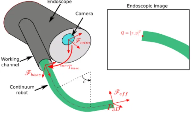
Fig. 1. Example view of the considered systems. Here c is the configuration variable representing bending of a bending section of the robot
the position of the tip and one measuring the proximal position are needed. It is desirable, in endoscopy, to use the camera, which is readily available at the distal part of the endoscope, because integrating sensors in the small diameters instruments is still a practical problem.
The method developed by Reilink et al. [13] allows esti-mating and compensating backlash by using the endoscopic camera. Corrected motor positions are reconstructed from the images by relying on a model of the continuum robot, which is equivalent to an implicit robot pose estimation. As shown in [14], such models are inaccurate in realistic conditions, due to the uncertain position of the instrument in the endoscope channel, which impacts the eye-to-hand regis-tration. Moreover, the approach only allows for compensating uniform backlash. As shown in Fig. 2, the characteristics of cable driven instruments actually present complex non-linearities. Baek et al. [15] recently proposed compensating hysteresis by fusing image and kinematics information for bending angle estimation and have shown robustness to image occlusions and guide shape variations. The method however relies on the offline training of neural networks and therefore cannot be directly applied in-situ for new instruments.
In this work we propose to estimate the backlash by using the embedded camera at the tip of the endoscope, which looks at a moving continuum robot (see Fig. 1). We show that the problem of estimating the global non-linear behavior of the bending DOF of the instrument can be split in two sub-problems : estimating a pure backlash, whose width can depend on the configuration of the robot, and then estimating the remaining function. We show that the pure backlash can be estimated from image movement detection, without measuring the pose of the robot. This is
an interesting feature, as pose estimation from monocular camera in in vivo environments is a complex problem. In cases where the pose can be estimated, it is then possible to estimate the remaining function while keeping the initial pure backlash estimate.
The paper is organized as follows. Section II presents the model used in the development of the method. Section III and IV respectively describe the proposed approach for pure backlash and remaining function estimation. Section V presents the validation of the method and results obtained both for predicting the behavior of the robot and compen-sating the non-linearities. A discussion concludes the paper.
II. MODELING OF ROBOT BEHAVIORS
In this work we consider a cable driven continuum robot observed by an endoscopic camera in an eye-to-hand configuration. This configuration is common in many medical robotic devices developed for endoluminal surgery [2], [16]–[18] or single port laparoscopic surgery [3], [19]. Such devices are usually equipped with sensors at the proxi-mal side only (i.e. encoders mounted onto the drive system). This minimal setup, where no additional sensor –except the endoscopic camera– is available at the distal side, is the case considered in this study (see Fig. 1).
The state of the continuum robot can be represented in different spaces:
• in the actuator space, where it is described by a vector of motor positions q
• in the configuration space, where a vector of configu-ration variables c describes the geometric arrangement of the robot
• in the task space, for instance by the position baseP3D and orientationbaseRe f f of the continuum robot effector with respect to the base frame
• in the image space, by the perspective projection of points of the continuum robot body, for instance Q, the projection of P3D.
For each space, the parameters to be used and their number required for representing the robot depend on its design.
In this work, we assume that the relation between the configuration space and the task space is known, i.e. one can compute the position/orientation of the robot end effector given a set of configuration variables. This can be done for instance by relying on a geometric model of the robot (for instance a constant curvature model [20]). It is written as: P3D= g(c), g : Rn→ R3.
On the contrary, the link between the actuator space and the configuration space c = f(q) is only coarsely known. In the considered systems, it is usual that conventional kine-matic models do not account for complex behaviors in the motion transmission. This is especially true for robots with flexible shafts and for the tendon-driven DOFs. Some of the observed behaviors are shown in figure 2. A coarse function denoted fcoarse is assumed to be available, for instance a simple kinematic model assuming perfect transmission. The core of this work is to estimate the actual relation between actuator space and configuration space.
Tool tip bending angle (deg.)
Motor position (deg.)
Fig. 2. Non-linear behaviors measured on a tendon driven DOF of a continuum robot, between proximal actuator and distal configuration. The different colors correspond to different dates of measurement between in vivoexperiments. Strong variations can be observed.
The transformation between the task space and the im-age space is also only coarsely known. The camera is assumed calibrated and a nominal eye-to-hand transform cam¯t
base, camR¯base is available, which allows estimating
Q∼ ˆQ= h(P3D). However, as shown in [14], the
hand-eye calibration in endoscopic systems includes uncertainties linked to the necessary mechanical play for translating and rotating instruments in the working channel.
A. Modeling of the quasi-static non-linearities
We consider one tendon-driven degree of freedom of the continuum robot. The non-linearity in the behavior of this DOF can be represented by the hysteresis shape relating q (one element of q) to the obtained configuration variable c (one element of c), usually a bending angle. As shown in figure 2 the hysteresis can have a complex shape. In our approach we propose to decompose this global non-linearity in two parts, as shown in figure 3:
1) A backlash, which appears at a change of direction of the actuator. This is responsible for the hysteresis shape of the characteristic curve. In the following we call this part ”pure backlash”. The approach proposed in [13] considered a constant backlash. There is, however, no reason to consider the backlash constant a priori. Therefore our method identi-fies the relation between the actuator position and the width of the backlash and express it as a function B(q) (see section III). This modeling implies that the backlash is symmetric, i.e. for a given distal configuration the absence of motion happens on the same motor range, whatever the direction of the motor motion.
2) A function fremain(q), generally non-linear, which links the actuator position to the configuration variable value once pure backlash has been removed or compensated. In the following we call this function the remaining function. This function can also be viewed as the central line of the hysteresis curve. It should be noted that it is generally different from the envelope functions of the hysteresis (see for instance figure 6).
actuator position q kinematics g( ) camera model (projection) h( ) transmission configuration variables c cartesian position in operational space P3D projection in the image Q BacklashB fREMAIN( ) q
{
c direct modelFig. 3. Proposed modeling of the continuum robot, where transmission non-linearities are split in two parts.
Backlash B Motion generation + Marker segmentation Image motion detection local backlash estimation global backlash model construction estimation of the configuration variables complete direct and inverse model 1 2 3 4 5 6 extraction of fREMAIN(q) fREMAIN(q)
Fig. 4. General scheme used for non-linearities estimation. The upper part of the block-scheme (blocks 1 to 3) concerns estimation of pure backlash while the lower part (blocks 4,5) processes the remaining function. They are combined to provide the complete estimate (block 6).
Representing complex hysteresis shapes by combining a backlash operator and a function, as shown in figure 3, has for instance been proposed in [21]. However, identifying the two parts separately is a novel approach. It is of interest here because the two parts can be obtained from different information as will be shown in the following. The next sections present the proposed method in details. The general scheme is depicted in figure 4.
III. PURE BACKLASH ESTIMATION
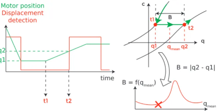
A. Estimation of the backlash at a given motor position Pure backlash can be characterized by the absence of end-effector motion after a change of direction of the actuator at the proximal side. The backlash width is then simply the range of motor motion which does not create distal motion. The proposed approach therefore consists in detecting the appearance of motion after a change of motor direction. The absence of motion and the appearance of motion are events which are directly visible in the image and which do not require a 3D pose estimation process.
The process for backlash estimation is as follows (Fig. 5): • The position of the effector is tracked in the image • An actuator direction change (change of sign( ˙q)) is
re-quested at time t1and the corresponding motor position q1 is recorded
• When a movement is detected in the image at time t2, the corresponding position q2is recorded
The backlash width can be considered as a function of the distal configuration c. However, c is not directly accessible with the considered setup and its estimation would require a pose estimation process. Therefore, it is more convenient to describe the backlash width as a function of an actuator position, which is readily available. We have chosen to express the backlash width as a function of the mean actuator position in the backlash zone qmean = q1+q2 2. The value of width is then given by B(qmean) = |q2− q1| and it can
Motor position Displacement detection q c t2 t1 q2 q1 B = f(qmean) B qmean B = |q2 - q1| qmean time t1 t2 q2 q1
Fig. 5. Pure backlash estimation scheme. Left: actuator motions for a requested change of direction, and the detected motion in the image in function of time. Top-right: corresponding evolution in the configuration vs actuator space. Bottom-right: The measured backlash width provides a point in the backlash width function.
represent backlash for both direction changes (positive to negative velocity and negative to positive velocity). Actually, since different sources of information are used to obtain t1 and t2 a correction is needed to temporally align image measurements and motor measurements. This is especially important when using low frame rate image acquisition systems, which also introduce delays. We then use
B(qmean) =
q(t2− tdelay) − q1
, (1)
where tdelay is the temporal delay introduced by the image acquisition and processing pipeline. It is assumed here that the motor positions are obtained at a high frame rate with negligible delay as is usually the case.
This simple process is independent of any robot model or 3D position estimation process. It is therefore also indepen-dent on the calibration parameters of the camera and of the eye-to-hand transform camT
base.
B. Construction of the backlash width function
As the backlash width depends on q, the method presented in section III-A must be performed at different actuators positions, in order to estimate the function B(q) over a useful range of actuators positions. For an in situ estimation prior to use, typically after the medical robot insertion in the body but before the actual surgical use, a pre-programmed motor trajectory can be used to reconstruct the backlash width function B. This trajectory can consist in several small range back and forth motions superimposed on a ramp which covers the full range of the useful motor positions. Using this pre-programmed trajectory, one can estimate values of B(q) over the desired range, but only at discrete intervals. Using the backlash model for compensation (see section III-C) requires however a continuous function for all motor positions. We propose to interpolate and filter the obtained values by using cubic B-splines, with N control points homogeneously spread over the motor range. This choice was made based on the observation that hystereses obtained with external sensors in [10] exhibit an overall smooth variation but with possible high local slopes.
Given the initial coarse model of the q → c mapping c = fcoarse(q) the direct complete model of the non-linearities can
motor position q (mm) f1 f2 fremain predicted configuration c (rad) motor position q (mm)
predicted configuration c (rad)
f2
f1 fcoarse
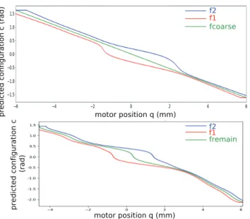
Fig. 6. Reconstructed hystereses, by combining a linear fcoarsefunction with pure backlash (top) and by combining estimated fremainwith backlash (bottom).
be obtained by combining the backlash model and the fcoarse function. The external envelope defined by functions f1 and
f2can be obtained by a numerical reindexing of fcoarse: f1,2(qo f f) = fcoarse(q) with qo f f = q ∓
B(q)
2 (2)
This is illustrated in figure 6 (top), where fcoarse is linear.
Note that because B generally depends on q, f1,2 are not
linear. The variable backlash model enforces a deformation of the external envelope.
At a time index k the direct model can be numerically simulated by (see [22]): c[k] = f2(q[k]) if q[k] > q[k − 1] and c[k] ≥ f2(q[k]) f1(q[k]) if q[k] < q[k − 1] and c[k] ≤ f1(q[k]) c[k − 1] otherwise (3)
C. Use for backlash compensation
The identified model can be used to compensate the back-lash. Given a reference trajectory c∗(k) for the configuration variable, the compensated reference motor trajectory can be computed as : q∗[k] = F1inv(c∗[k]) if c[k]∗< c[k − 1]∗ F2inv(c∗[k]) if c[k]∗> c[k − 1]∗ q∗[k − 1] if c∗[k] = c∗[k − 1] (4) where ( F1inv(c∗) = ˆfcoarse−1 (c∗) − B( ˆfcoarse−1 (c∗)) 2 F2inv(c∗) = ˆfcoarse−1 (c∗) + B( ˆfcoarse−1 (c∗)) 2 (5) ˆ
fcoarse−1 is the inverse function of fcoarse, which can be obtained by a numerical inversion. Smoothing can also be added to transitions to avoid actuator saturation [12].
This compensation can advantageously be used in a tele-manipulation framework, for correcting the behavior of the
robot when a change of direction of the distal configuration variable is required. It can thus avoid apparent delays in executing the user’s reference trajectories.
IV. REMAINING FUNCTION RECONSTRUCTION
For automatic motions realization, as described in [10], the compensation of backlash alone is not sufficient for providing a good positioning accuracy. Indeed, fcoarse is usually inaccurate, and therefore f1,2 are also. There are for instance dead zones near the straight configuration, as
shown in figure 2 (green curve, between 0◦ and 10◦ for
instance), which are difficult to predict from models. This means that even if backlash may be correctly compensated when changes of direction are required, the link between the rate of variation of c∗ and of q∗ can be incorrect. In other words, the task space position can be inaccurate. For improving accuracy, one can estimate the complete hysteresis envelope, i.e. f1 and f2, from data. These functions link the actuator positions to the configuration variable values as long as no change of direction is applied. This information can be obtained from the endoscopic camera only if the configuration variable can be extracted from the image. This in turn requires a geometric model of the continuum robot, a model of the camera and of the eye-to-hand configuration. Such techniques have been used to reconstruct three [23] or six configuration variables [14]. In the considered case where a single DOF has to be estimated, a marker at the tip of the instrument coupled with a conventional geometric model (for instance a constant curvature model) is sufficient. We propose an approach similar to [23], but instead of reconstructing a corrected motor position, we focus on the configuration variable c. Given a model of the endoscopic camera and of the eye-to-hand calibration, we have :
ˆ
Q= h(g(c)) (6)
We denote the interaction matrix (image jacobian) which relates the variation of c to the variation of ˆQby J :
d ˆQ dt = J dc dt with J = ∂ h ◦ g ∂ c (7)
Given a position of the marker in the image Q, one can estimate the optimal value of c by minimizing the cost function L = kQ − ˆQk2 by using an iterative optimization process such as Levenberg-Marquardt:
ˆ
cj= ˆcj−1+ (JTJ+ λ (diag(JTJ))−1JT(Q − ˆQ) (8) Note that this approach, as the ones used in [14], [23], minimizes the error of a projection in the image. This scheme can therefore succeed and provide very low projection errors even when models are erroneous. In such cases, the obtained values for the configuration variables will be inaccurate.
By applying this estimation process during the pro-grammed motion of the instrument used for pure backlash estimation as described in section III-B, one can reconstruct the hysteresis characteristic curves (see Fig. 9). After this step, the functions defining the external envelope of the hysteresis could be used to compute the width of the backlash
in function of qmeanas for instance in [10]. However, in this case the pure backlash estimation obtained previously would be overwritten. This is not desirable, because contrary to [10] where accurate external sensors are used, the process used here to estimate c is subject to modeling and measurements errors. We therefore propose to keep the initial pure backlash estimation, which was obtained independently of any pose estimation, and to estimate the remaining function. For this purpose the remaining function is estimated as the central fiber of the characteristics, i.e. the horizontal median line of the envelope. For extracting it, the characteristic is processed as an image by applying morphological operations for filling holes, extremal horizontal values detection and spline fitting. This provides function fremain: q → c, as shown in figure 9. The complete obtained model can for instance be used for an automatic positioning task as will be shown in section V. Given a desired trajectory c∗[k] for the configuration variable, the required actuator position can be obtained using eq. (4), but replacing fcoarsewith fremain
( F1inv(c∗) = fremain−1 (c∗) + B( fremain−1 (c∗)) 2 F2inv(c∗) = fremain−1 (c ∗) −B( fremain−1 (c∗)) 2 (9) V. SIMULATION AND EXPERIMENTS VALIDATION Several simulations and experiments were carried out to show the validity of the approach and its possible interest. A. Experimental setup
We consider the left instrument of the STRAS robotic platform [18] (see Fig. 12). The instrument has three DOF : translation, rotation and bending. The bending DOF, which is actuated by antagonist cables is the main focus of the experiments. The robot DOFs are controlled in position by a real-time control PC (see [18] for details). Endoscopic images are acquired at 25 Hz through a framegrabber. Image processing codes are in C++ on a separate computer, which sends high-level commands to the real-time control PC, where inverse backlash models are implemented.
B. Simulation
The proposed approach is first studied in simulation of the above-mentioned system, in order to show the interest of our method in controlled conditions. We simulate the robot using a perfect constant curvature model, with a
hysteresis of constant width 15o on the bending DOF. We
consider in addition that the instrument can slightly move in its working channel (as shown in [14]). Therefore, we
introduce a ±1.5◦ error around the y axis on the
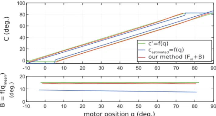
hand-eye registration matrix, the sign depending on the distal motion direction. We then reconstruct the pure backlash and remaining function as described in sections III-C and IV, with bending velocities at 15◦/s. For comparison purposes, we also reconstruct the hysteresis in a single step by directly estimating the configuration variable (see section IV).
Figure 7 shows the obtained hysteresis cycles and the estimated backlash in both cases. As could be foreseen backlash reconstruction is impacted by the slight registration
C (deg.) B = f(q mean ) (deg.) c*=f(q) cestimated=f(q) our method (Fnl+B)
motor position q (deg.)
Fig. 7. Reconstructed hysteresis (top) and backlash width function (bottom) as a function of q. The robot is simulated with a constant 15◦backlash on the bending joint, and a ±1.5◦ error on the hand-eye calibration. Green: ground truth, Blue: Direct single-step estimation of the hysteresis using pose estimation, Red: using the proposed approach.
error, even with a perfectly known constant curvature model. Our proposed two-step approach accurately estimates the backlash (mean error 0.7◦(4.7%), std. 0.09◦), while the model-based estimation features large errors (mean error 6.6◦(44%), std. 0.51◦).
It has to be noted that this simulation example was cho-sen on purpose to exhibit limitations of more conventional approaches relying on pose estimation and configuration variable reconstruction. However, it shows that avoiding pose estimation can be useful in realistic cases.
C. Image measurements
The continuum robot end effector needs to be tracked in the image. Since a single DOF is considered, it is sufficient to track a single point. Since the focus of the present work is not on the image processing aspects, we used a simple colored marker attached at the tip of the instrument, which can be efficiently tracked using simple image processing techniques. More advanced marker-based
or marker-less methods [14], [15], [23]–[25] can be used
for in vivo settings. D. Backlash estimation
The delay of the image acquisition chain has been
es-timated to 2 frames (i.e. tdelay = 80ms), with an
uncer-tainty ∆tdelay = 20ms (half period). Assuming a constant
velocity of the actuator v during backlash crossing, this creates an estimation error ∆q = k∆tdeltavk on q(t2− tdelay). It is therefore recommended to apply a low velocity for backlash estimation. Practically, the velocity is set to 5% of the maximum motor velocity, which corresponds approx-imately to a maximum bending speed of 20◦/s at the distal end.The corresponding uncertainty onto the actuator position is 0.025mm of cable displacement. For separating motion and absence of motion, the image position of the marker Q is differentiated and a threshold T is applied. T was set to 0.2 pixels/frame after practically assessing that the noise for still marker localization was less than 0.15 pixels.
Figure 8 shows the backlash estimation as a function of the motor position. The continuous function has been obtained
−2 0 2 4 6 3.0 2.5 2.0 1.5 1.0 0.5 0.0 mm b−spline regression −4 mm
Fig. 8. Backlash width (measurement (dots) and B-spline based recon-structed shape (red line)) as a function of the mean actuator position. Blue lines show the spline knots positions. Units are in mm of cable displacement.
1.0 1.5
−4 −2 0 2 4
remain f (q)
configuration variable c (rad)
motor position (mm) −1.5 −1.0 −0.5 0 0.5
Fig. 9. Characteristics between the actuator and configuration variable obtained using configuration variable estimation from images.
by B-spline fitting with N = 14 knots (8 central and 3 at each extremity of the motor range). One clearly observes the strong increase of the backlash near the center of the motor range (straight configuration of the instrument). This behavior was already observed in [10], [26]. This clearly confirms the need of a variable backlash estimation method (see section II-A).
E. Remaining function estimation
The remaining function was estimated using the same input images and motor data as for the backlash width. The typical actuator / configuration characteristics are shown in figure 9. fremainis then extracted as described in section IV. F. Assessment of prediction capability
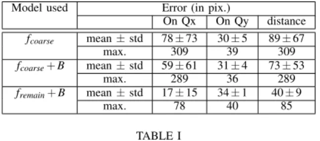
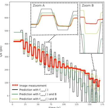
For assessing the validity of the pure backlash and the re-maining function estimation, a testing motion is used, which consists in periodic trapezoidal back and forth motions realized with the motor actuating bending superposed on a linearly varying mean value (see Fig. 10 and accompanying video). This trajectory includes many changes of directions, in order to exhibit the effects of backlash. The position of the instrument is tracked in the endoscopic image, and the actual trajectory is compared with the modeling obtained with fcoarse (pure kinematic model of the instrument [27]), with fcoarsecombined with backlash estimation only ( fcoarse+ B) and with the complete estimation ( fremain+ B) (see Fig.11). Results are presented in table I.
Model used Error (in pix.)
On Qx On Qy distance fcoarse mean ± std 78 ± 73 30 ± 5 89 ± 67 max. 309 39 309 fcoarse+ B mean ± std 59 ± 61 31 ± 4 73 ± 53 max. 289 36 289 fremain+ B mean ± std 17 ± 15 34 ± 1 40 ± 9 max. 78 40 85 TABLE I
COMPARISON OF PREDICTION ERRORS IN THE ENDOSCOPIC IMAGE USINGfcoarse, fcoarse+ BANDfremain+ B. THE ERRORS ARE SHOWN FOR
THExAXIS(Qx),THEyAXIS(Qy)AND IN NORM(DISTANCE).
When using fcoarseonly, the norm of the error in the image shows large pseudo-periodic variations, with a mean distance error of 89 pixels. This is mainly due to the prediction going on either side of the actual position, because the absence of movement at the distal tip at the change of direction is not predicted. The combination of the backlash with fcoarse allows to greatly decrease the amplitude of the squares because, at each change of direction, the model predicts the range of motor motion that does not create distal motion. Zoom A on Fig. 10 shows that the appearance of motion in the image at each cycle is well synchronized between prediction and measurement. However, the prediction shows larger amplitudes of motions than the measurement, and the mean distance error only decrease to 73 pixels. This arises from an incorrect prediction of the rate of variation at the distal side. Namely, the rate is overestimated because fcoarsedoes not correspond to the actual remaining function.
This is especially visible between 150s and 175s (see
zoom B) because the instrument comes close to the straight configuration, where the actual rate of motion is very low and the discrepancy with fcoarse particularly large. Note, however, that the synchronization of motions remains good, indicating that the backlash is well estimated. When using the complete model with fremain, the velocity of distal movement is better predicted, which allows an important reduction of the prediction error to 40 pixels. In zoom B, the remaining function only allows to slightly decrease the error on the image position prediction. The remaining error can be due to the transition movement between backlash and the envelope function or to coupling effects.
It can be noted that the norm of the error never goes under 40 pixels. This comes from errors in the registration between the endoscopic camera and the robot, which mainly affect the vertical position (Qy) of the instrument in the image. In the presented experiments, the motion of the instrument is mainly along the horizontal axis of the image, so that the error on Qy is almost constant (see table I). The prediction error along the horizontal axis (Qx) is therefore significantly reduced from 78 pixels to 17 pixels when using fremain+ B. G. Assessment of compensation capability
The inverse non-linear models have been implemented onto the robotic system. For assessing the effect of
com-Image measurement Prediction with fcoarse( ) Prediction with fcoarse( ) and B Prediction with fremain( ) and B
time (s)
Qx (px)
Zoom A Zoom B
Fig. 10. Pseudo-periodic trajectory used for testing prediction capability of different models: fcoarse(black), fcoarse+ B (green) and fremain+ B (yellow). Zooms A and B show that when backlash is modeled the appearance of motion is well synchronized with the measurement.
Error with fcoarse( ) Error with fcoarse( ) and B Error with fremain( ) and B
time (s)
Nor
m of the er
ror
(px)
Fig. 11. Reprojection errors between the measured position of the effector in the endoscopic image and the prediction of effector position provided by
fcoarse(black), fcoarse+ B (green) and fremain+ B (yellow).
pensation, a 2D trajectory (an ellipse) is defined in the task space of the continuum robot. The configuration trajectory (bending, rotation, translation) is computed using the inverse geometric model of the instrument [27]. The obtained tra-jectory is then performed in open-loop and observed by an external camera parallel to the plane of the ellipse. Figure 12 provides the qualitative results. The non-linearity compensation allows to largely improve the accuracy of the trajectory.
VI. DISCUSSION AND CONCLUSION
We have presented a method for estimating non-linearities of cable-driven continuum robots, which uses an endoscopic camera conventionally available in endoluminal digestive surgery and which is thus suitable for in situ use. The method has been shown valid for free moving continuum instruments through laboratory experiments, both for predicting the robot behavior and for compensating the non-linearities.
One originality of the approach is to separate hysteresis estimation in two parts, and to estimate pure backlash without relying on pose estimation. This is an interesting
+
25 mm 8 mm
Endoscopic camera
Fig. 12. Open loop realization of a reference trajectory (yellow), by relying on f−1
coarse(blue) and on the inverse model constructed from fremain+ B (see
eq. 9) (green)
feature because pose estimation in in vivo environments is a complex task [14]. Here, backlash is obtained from motor measurements and image measurements only. Tracking a single point on the instrument in the image is sufficient, and there is no need to combine several image information to estimate a pose or a configuration variable (as for in-stance proposed in [13], [14], [23]) or to use data acquired beforehand on the system as proposed in [15]. Moreover, methods based on models need to handle singularities in the process of 3D information reconstruction. Such singu-larities can come from the kinematics of the continuum robot (for instance, rotation is ill-defined around the straight configuration of the instrument) or from the image jacobian which links instrument tip motion to its apparent motion in the image. There are solutions to avoid such singularities, but a specific technique should be designed, which may be difficult to implement in cases where the available models are erroneous. Therefore, the proposed approach is well adapted for estimating backlash in situ.
The method also allows to take into account non uniform backlash, which is generally the case as shown in figures 2 and 8. When identified, pure backlash can be compensated, which can improve user experience during teleoperation. If pose estimation can be obtained, it is possible to es-timate proximal to distal position relation. Interestingly, the proposed approach allows complementing the backlash model, without changing it. Therefore, if pose estimation turns out erroneous because of modeling or measurement errors, the backlash compensation won’t be affected. This is an important improvement over the method in [13], where complete hysteresis estimation relies on pose estimation. Indeed, simulations show that slight errors on the camera / robot registration can have a large impact on the estimation of backlash when relying on configuration variable recon-struction (see Fig. 7).
As seen in figures 10, 11 and 12, errors remain, which have several identified sources:
1) As expected, the estimation of fremain depends on 3D position estimation, which is subject to modeling errors (non uniform curvature of the robot, for instance).
2) By separating pure backlash and remaining non-linear function, it is assumed that the system directly switches from the pure backlash to the envelope function of the hysteresis. However, it can be observed in Fig. 2 that smooth transitions can exist. These transitions cannot be directly modeled with the proposed approach because they would require reconstructing a rate of change of the configuration variable.
3) It is also assumed that backlash is symmetric. Complex coupling effects in the motion transmission of the instrument could create non symmetric backlash. This could be one source of the errors observed in Fig. 10, zoom B.
4) The proposed approach mainly deals with quasi static non-linearities. With the given setup, which relies on en-doscopic images, it won’t be possible to measure dynamic effects such as stick-slip, because the acquisition framerate is too low. In an extension of the work, it could be possible to try decreasing the effects of such dynamic non-linearities, for instance by designing acceleration trajectories that limit their appearance.
It should however be noted that these difficulties also affect other techniques for hysteresis compensation relying on the use of endoscopic images, and as shown in section V the obtained results are satisfactory.
The motions of the guide of the instruments (the endo-scope) are also impacted by its own non-linearities. While our work mainly aimed at improving the control of the instruments, which is of higher importance during surgical stages, it could also be useful to compensate non-linearities of the guide during navigation stages. The proposed approach requires to see the motions of the continuum robot in images in an eye-to-hand configuration, and therefore cannot be directly applied to the eye-in-hand configuration of the endo-scope. The proposed approach could possibly be extended to estimate motion / absence of motion in such a configuration, for instance using motion-compensated SLAM algorithms [28]. This is however out of the scope of the current article. Non-linearity estimation, prediction and compensation were realized for free motions of the robot. Contacts would impact the validity of the method. Therefore, it is mainly aimed at non contact tasks, such as optical coherence to-mography biopsy or laser dissection. As a future work, we aim at adapting the proposed method to make it ”on-line”, i.e. working during the actual use of the system. A first approach would be to generate very small motions, just larger than the actual backlash, when instruments are not moved by the user. Another approach would be to rely on the motions generated by the user.
REFERENCES
[1] J. Burgner-Kahrs, D.C. Rucker, and H. Choset, Continuum robots for medical applications: a survey, IEEE Trans. Robot., vol. 31, no.6, pp.1261-1280, Dec. 2015.
[2] https://medrobotics.com/gateway/flex-robotic-system/?c=INTL, com-mercial website of Medrobotics, accessed on 05/19/20.
[3] https://titanmedicalinc.com/technology/ , commercial website of Titan Medical, accessed on 05/19/20.
[4] V. Agrawal, W. Peine and B. Yao, Modeling of Transmission Characteristics Across a Cable-Conduit System, IEEE Trans. Robot., vol. 26, no. 5, pp. 914-924, Oct. 2010.
[5] J. Jung et al., A modeling approach for continuum robotic manipu-lators: Effects of nonlinear internal device friction, in IEEE/RSJ Int. Conf. Intell. Robots and Systems, San Francisco, California, Sep. 2011, pp. 5139-5146.
[6] T. N. Do et al., Hysteresis modeling and position control of tendon-sheath mechanism in flexible endoscopic systems, Mechatronics, vol. 24, no.1, pp. 12-22, Feb. 2014.
[7] Z. Sun, Z. Wang, S.J. Phee, Elongation Modeling and Compensation for the Flexible Tendon-Sheath System, IEEE/ASME Trans. Mecha-tronics, vol. 19, no. 4, pp. 1243-1250, Aug. 2014.
[8] R. J. Roesthuis, S. Janssen, S. Misra. On using an array of fiber Bragg grating sensors for closed-loop control of flexible minimally invasive surgical instruments, in IEEE/RSJ Int. Conf. Intell. Robots and Systems, Tokyo, Nov. 2013, pp. 2545-2551.
[9] H. Liu et al., Large deflection shape sensing of a continuum manip-ulator for minimally-invasive surgery, in Proc. 2015 IEEE Int. Conf. Robot. Automat., pp. 201-206.
[10] R. Aleluia Porto, F. Nageotte, P. Zanne and M. de Mathelin, Position control of medical cable-driven flexible instruments by combining machine learning and kinematic analysis, in IEEE Int. Conf. Robot. Automat., Montreal, May 2019, pp. 7913-7919.
[11] W. Xu et al., Data-driven methods towards learning the highly non-linear inverse kinematics of tendon-driven surgical manipulators, Int. J. Med. Robot. Comput. Assisted Surgery, vol. 13, no. 3, 2017. [12] L. Ott , F. Nageotte, P. Zanne, M. de Mathelin, Robotic Assistance
to flexible endoscopy by physiological motion tracking, IEEE Trans. Robot., Volume 27, no 2, pp. 346-359, Jan. 2011.
[13] R. Reilink, S. Stramigioli and S. Misra, Image-based hysteresis reduc-tion for the control of flexible endoscopic instruments, Mechatronics, vol. 23, no.6, pp. 652-658, Sept. 2013.
[14] P. Cabras et al., An adaptive and fully automatic method for estimating the 3D position of bendable instruments using endoscopic images, Int. J. Med. Robot. Comput. Assisted Surgery, vol. 13, no. 4, Dec. 2017. [15] D. Baek et al., Hysteresis Compensator with Learning-Based Hybrid
Joint Angle Estimation for Flexible Surgery Robots, IEEE Robot. Automat. Lett., Feb. 2020.
[16] http://easyendosurgical.com/, website of EasyEndo, accessed on 05/19/20.
[17] D. J. Abbott, C. Becke, R. I. Rothstein, and W. J. Peine, Design of an endoluminal notes robotic system, in IEEE/RSJ Int. Conf. Intell. Robots and Systems, San Diego, California, Oct. 2007, pp. 410-416. [18] L. Zorn et al., A Novel Telemanipulated Robotic Assistant for Surgical
Endoscopy: Preclinical Application to ESD, IEEE Trans. Biomed. Eng., vol. 65, no. 4, pp. 797-808, Apr. 2018.
[19] J. Ding, R. E. Goldman, K. Xu, P. K. Allen, Fowler, and N. Simaan, Design and coordination kinematics of an insertable robotic effectors platform for single-port access surgery, IEEE/ASME Trans. Mecha-tronics, vol. 18, no.5, pp. 1612-1624, Oct. 2013.
[20] R. J. Webster and B. A. Jones, Design and kinematic modeling of constant curvature continuum robots: A review, Int. J. Robot. Res., vol. 29, no. 13, pp. 1661-1683, Jun. 2010.
[21] Y. Rochdi et al., Identification of block-oriented systems in the presence of nonparametric input nonlinearities of switch and backlash types, Automatica, vol. 46, no.5, pp. 864-877, May 2010.
[22] J. V¨or¨os, Modeling and identification of systems with backlash, Automatica, vol. 46, no. 2, pp. 369-374, Feb. 2010.
[23] R. Reilink, S. Stramigioli and S. Misra, 3D position estimation of flexible instruments: marker-less and marker-based methods, Int. J. Comput. Assisted Radiol. and Surgery, vol. 8, no. 3, pp. 407-417, May 2013.
[24] A. Reiter, R.E. Goldman, A. Bajo et al. A learning algorithm for visual pose estimation of continuum robots, in IEEE/RSJ Int. Conf. Intell. Robots and Systems, San Francisco, California, 2011, pp. 2390-2396. [25] B. Rosa, V. Bordoux, F. Nageotte, Combining differential kinematics and optical flow for automatic labelling of continuum robots in minimally invasive surgery, Frontiers Robot. AI, Frontiers Research Foundation, Online, Sep. 2019.
[26] B. Bardou et al., Improvements in the control of a flexible endoscopic system, in IEEE Int. Conf. Robot. Automat., Saint Paul, Minnesota, 2012, pp. 3725-3732.
for Minimally Invasive Surgery, in IEEE/RSJ Int. Conf. Intell. Robots and Systems, Tokyo, Nov. 2013, pp. 483-489.
[28] P. Mountney and G.Z. Yang, Motion compensated SLAM for image guided surgery, in MICCAI, Beijing, Sep. 2010, pp. 496-504.