The Development of a High Cooling and Low Ultimate Temperature Three
Stage Superfluid Stirling Refrigerator
by
Carolyn L. Phillips
B.S., Mathematics
Massachusetts Institute of Technology, 1999
SUBMITTED TO THE DEPARTMENT OF MECHANICAL ENGINEERING IN
PARTIAL FULFILLMENT OF THE REQUIREMENTS FOR THE DEGREE OF
MASTER OF SCIENCE IN MECHANICAL ENGINEERING
AT THE
MASSACHUSETTS INSTITUTE OF TECHNOLOGY
SEPTEMBER 2001
@2001 Carolyn L. Phillips. All rights reserved.
The author hereby grants to MIT permission to reproduce and to distribute publicly paper and electronic copies of this thesis document in whole or in part.
MASSACHUSETTS INSTIEUT OF TECHNOLOGY DEC 10
2001
LIBRA
JIM , t Signature of Author: VBA1~tR
Department afechanical Engineering August 31, 2001 I
Certified by:__
John G. Brisson Professor of Mechanical Engineering Thesis Supervisor
Ain Sonin Professor of Mechanical Engineering Chairman, Committee for Graduate Students Accepted by:.
The Development of High Cooling Power and Low Ultimate Temperature
Three Stage Superfluid Stirling Refrigerators
by
Carolyn L. Phillips
Submitted to the Department of Mechanical Engineering On August 31, 2001 in Partial Fulfillment of the Requirements for the Degree of Master of Science in
Mechanical Engineering
ABSTRACT
The superfluid Stirling refrigerator (SSR) is a Stirling cycle refrigerator which provides cooling to below 2 K by using a liquid 3He-4He as a working fluid. In 1990, Kotsubo and Swift demonstrated the first SSR and by 1999, Patel and Brisson (Patel) had developed an experimental prototype capable of reaching a low temperature of 248 mK using two Stirling refrigerator stages. The goal of this thesis was also to develop a deeper
understanding of the SSR and the technical issues involved in its operation and also to further develop the SSR built by Patel.
This thesis is divided into four parts. In the first part, technical developments to the SSR are discussed. Also the details of the three-stage SSR developed for this work are
presented. In the second part, a two-stage SSR with larger recuperators are operated to see whether new ultimate temperature and cooling powers could be achieved. Operating from a high temperature of 1.05 K and with a 3.0% SHe-4He mixtures, this SSR achieved a low temperature of 329 mK and delivered net cooling powers of 1 mW at 606 mK, 500
pW at 408 mK. Next this thesis describes the operation of the first three-stage superfluid
Stirling refrigerator. Unfortunately, due to experimental difficulties, the merits of the three-stage SSR were not demonstrated and further work is still required. The lowest ultimate temperature reached by three-stage SSR was 338 mK from a high temperature of
1.07 K. The third part of this thesis sought to ascertain the heat dissipation due to the
flexing and relaxing of the bellows in the SSR. The dissipation of two types of bellows was measured at 1.4 K and the measurements were used to project dissipation rates for a family of similar bellows. In the fourth part of this thesis, a numerical analysis was developed to predict the distribution of 3He particles in the SSR during operation. This
analysis confirmed that the third stage of the SSR requires a working fluid separate from the first and second stage of the SSR in order to reach temperatures lower than 200 mK.
Thesis Supervisor: John G. Brisson
Contents
1. Introduction 10
1.1. T he Stirling C ycle... 12
1.2. Properties of 3He_ He mixtures... 14
1.3. Two phase region and the SSR... 17
1.4. H istory of the SSR ... 22
2. Experimental Apparatus 27 2.1. Description of the three-stage SSR... 27
2.2. Development of the Patel and Brisson SSR... 31
2.2.1. H eat Exchangers... 32
2.3. Heat leak in the third-stage fill lines... 34
2.3.1. Third Stage V alves... 35
2.3.2. Void Space Analysis... 36
3. Experimental Results of SSR 41 3.1. Review of the Experimental Results of the SSR... 41
3.2. Two Stage SSR with Large Upper and Lower Recuperator... 44
3.2.1. Description of Two-Stage SSR... 44
3.2.2. Experimental procedure and results... 47
3.3. Three-Stage SSR with two Large Recuperators and one Small R ecuperator... 52
3.3.1. D escription of SSR ... 52
3.3.2. Experimental procedure and results... 57
4. Metal Bellows Dissipation 60 4.1. Experimental Apparatus... 62
4.2. Procedure... 63
4.3. Development of Bellows Dissipation Model... 64
4.4. Bellows Dissipation in the SSR... 67
4.5. Temperature Limits on using Bellows Expander... 69
5. Theoretical Development 72 5.1. The Schmidt Model... 72
5.2. Sub-Kelvin Stirling Refrigerators... 76
5.3. Limitations of the 3He-4He Working Fluid... 76
5.4. Phonon and Roton Effects on 3He Concentration... 77
5.5. H eat E xchangers... 88
6. Summary and Conclusions 91
List of Figures
1.1 The States of the Stirling Refrigerator Cycle... 13
1.2 A Sketch of the Phase Diagram of the 3He-4He fluid. ... 15
1.3 The compression and expansion of 3He in a piston bypassed by superfluid 4H e ... 16 1.4 A single phase Stirling refrigerator using 3He in a superfluid 4He
background ... 17
1.5 3He-4He mixture in a piston in the two phase region. ... 18 1.6 A depiction of a Stirling cycle whose low temperature piston is operating
partially in the two phase region. ... 19 1.7 The states of the 3He-4He mixture in the low and high temperature piston
mapped onto a sketch of the phase diagram. ... 20
1.8 A representation of a single stage machine consisting of two back-to-back 1.9 180 degree out of phase SSR's exchanging heat through a recuperator... 23
1.10 A diagram of the two stage back-to-back SSR design with plastic
recuperators... 25
2.1 A schematic of the three-stage superfluid Stirling refrigerator. ... 28 2.2 The arrangement of alternate layers of Kapton templates within the
recuperator to form a counterflow heat exchanger. ... 30
2.4 A schematic of the dual superfluid tight valves. ... 35 2.5 An illustration of 3He particles flushed into a cold volume... 37
3.1 A schematic diagram of a two-stage SSR. ... 45
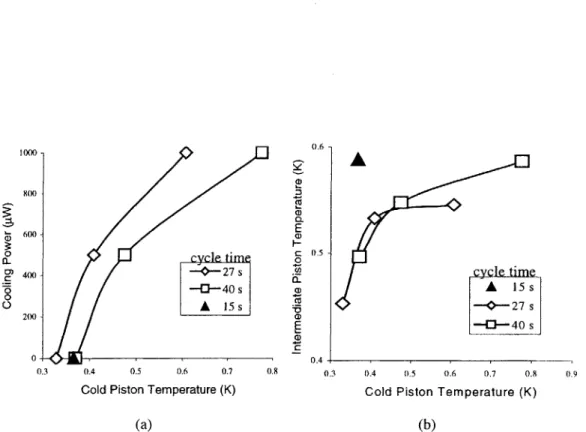
3.2 Data for a 1.1 cm compressor stroke and a 1.08 cm expander stroke. (a) Cooling power versus cold piston temperature for cycle times of 15, 27, and 40 seconds. (b) Intermediate Piston temperature versus cold piston tem perature for the data given in (a). ... 49
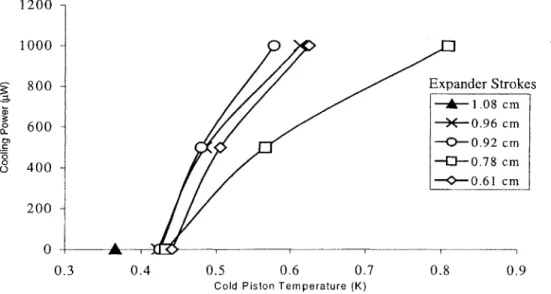
3.3 Data for cooling power versus cold piston temperature for a 15 second cycle period, 1.1 cm compressor stroke, and a range of expander strokes... 50 3.4 Data for cooling power versus cold piston temperature for a 23 second
cycle period, 1.1 cm compressor stroke, and a range of expander strokes... 50
3.5 Data for cooling power versus cold piston temperature for a 27 second
cycle period, 1.1 cm compressor stroke, and a range of expander strokes... 51
3.6 Data for cooling power versus cold piston temperature for a 40 second
cycle period, 1.1 cm compressor stroke, and a range of expander strokes... 51
3.7 A schematic of the three-stage SSR... 54
3.8 Calibration curves for resistance versus temperature of the carbon resistor thermometer mounted on the SSR's hot platform... 56 3.9 Data for the cold piston temperature versus third-stage cycle period for
different two-stage cycle periods... 59 3.10 Data for the cold piston temperature versus second intermediate compressor
piston for different two-stage cycle periods... 59
4.1 A schematic of the experimental apparatus used to measure bellows
dissipation ... 6 1
4.2 A plot of the measured bellows dissipation as a function of stroke length ...64
4.3 A annular disk model of bellows... 64 4.4 The weld bead which is modeled as the source of all dissipation. Dissipation occurs as the angle between the annular disks changes... 65
4.6 Non-dimensional energy versus non-dimensional stroke as per Eq. 4.3 in the text. The fit curve is Eq. 4.4 in the text... 66
4.7 Fraction of losses in the SSR due to bellows dissipation... 68
4.8 (a) Predicted cooling power minus bellows dissipation of a third-stage expander versus cold piston temperature. (b) The fraction the bellows dissipation makes up of the cooling power. These data points were generated using the Schmidt model to predict the cooling powers and
Eq. 4.4 to model the bellows dissipation... 69
4.9 A schematic of the idealized expander with valves... 69
4.10 Projected cooling power of non-ideal expander (a) and cooling power ratio of non-ideal expander to ideal expander (b) versus temperature... 70
5.1 An equation summary of the Schmidt model for a single stage Stirling
cy c le ... 7 3 5.2 The equation summary of the Schmidt model expanded to model a
two-stage Stirling device. A two-stage Stirling device consists of three pistons connected by two recuperators... 74
5.3 The equations summary for a Stirling cycle with an indefinite number of stages chained together... 75
5.4 The temperature distribution for a Stirling device is plotted versus position. The expansion and compression space are assumed to be isothermal. Three different temperature distributions for the regenerator are shown... 80
5.5 The 3He concentration of the cold, intermediate, and hot piston volume of a two-stage SSR plotted versus temperature. The black triangles correspond to the SSR with cold regenerators, the black diamonds correspond to the SSR with hot regenerators, and the squares correspond to the SSR with linear
regenerators... 82 5.6 The predicted minimum and maximum 3He concentrations of the hot,
intermediate, and cold piston volumes of four different models of the 3He distribution in the SSR are plotted versus temperature. The squares correspond to a model that includes both regenerator volumes and 4He
fountain pressure. The * correspond to a model that includes fountain pressure but omits the regenerator volumes. The triangles correspond to a model that omits fountain pressure but includes regenerator volumes. The circles correspond to a model that omit both fountain pressure and
regenerator volum es... 83 5.7 A plot of the 3He expected distributions versus temperature for three SSR's
with different total clearance volumes. The triangles correspond to an SSR whose clearance volume is 27% of its total volume. The * correspond to the same SSR with half that clearance volume (clearance volume is 15.6% of the total volume). The black squares correspond to the same SSR with no
clearance volum e... 85 5.8 The minimum and maximum 3He concentrations plotted versus temperature
for an SSR whose hot piston is at 1.05 K, intermediate piston at 0.5 K, and cold piston at 0.2 K and which was loaded with 3% mixture... 85
5.9 The maximum and minimum concentrations of 3He are plotted for the cold piston volume and hot piston volume of a single stage SSR whose cold and
hot pistons are at 0.1 K and 0.3 K. The squares correspond to the SSR
loaded with a 3% 3He mixture and large recuperators (6.05 cm2). The
triangles correspond to an SSR loaded with 3% 3He mixture with small recuperators (1.5 cm2). The diamonds correspond to an SSR loaded with
1.5% 3He mixture and large regenerators (6.05 cm2)... 86 5.10 Curves of constant 3He osmotic pressure... 87 5.11 Maximum and minimum 3He concentrations for the hot and cold piston of a
single stage SSR. The square correspond to an SSR modeled using the numerical Boltzmann model loaded with a 3% mixture. The diamonds correspond to an SSR modeled using the numerical Boltzmann model loaded with a 1.5% mixture. The * corresponds to an SSR modeled using the interpolated data model loaded with a 3% mixture. The black triangles correspond to an SSR using the interpolated data model loaded with a 1.5% m ixture... . 88 5.12 The change in 3He moles in three regenerators over the cycle... 89
5.13 A graph of the change in 3He moles in the hot piston and hot regenerator in the two-stage SSR over the cycle... 89
5.14 A graph of the change in 3He moles in the cold piston and cold regenerator
in the two-stage SSR over the cycle... 90 5.15 A graph of the change in 3He moles in the cold piston and the regenerator in
List of Tables
3.1 Single Stage SSR 's... 42 3.2 Tw o-Stage SSR 's... 43
3.3 A comparison of the performances of Patel's different SSR's... 44
3.4 Displacement volumes and clearance spaces for different expander strokes... 48 4.1 Manufacturer's specifications for bellows... 62 5.1 The specifications for the SSR modeled unless otherwise specified... 81
Chapter
1
Introduction
This thesis is a continuation of research in the development of the superfluid Stirling refrigerator. The superfluid Stirling refrigerator (SSR) is a Stirling cycle refrigerator that uses 3He He as the working fluid to cool to sub-Kelvin temperatures. The basic
components of a single stage Stirling refrigerator are a hot (compressor) piston and a cold (expander) piston connected by a regenerator. The cyclic compression and expansion of the ideal gas within these pistons pumps heat from the cold temperature reservoir to the high temperature reservoir. For temperatures below 1 K, the 3He component of the 3
He-4He mixture behaves as an ideal gas in an inert background of superfluid 4He. Superleak bypasses in each piston allow the superfluid 4He component to flow freely through the pistons while the 3He is expanded and compressed within the piston cylinders.
Kotsubo and Swift demonstrated the first single stage SSR in 1990 [1,2]. In 1992, Brisson and Swift further developed and improved the single stage SSR performance by using a recuperative SSR design [3-6]. In the latter design, two refrigerators are operated
180 degrees out of phase with each other and a counterflow heat exchanger is used as the
regenerator. This SSR design is more practical since there is a dearth of low temperature materials that can provide the high heat capacity necessary for an efficient regenerator matrix. This first recuperator was made of CuNi tubes. Brisson and Swift achieved a low temperature of 296 mK while operating from a high temperature of 1.05 K. Using
the same machine, Watanabe, Swift, and Brisson later reached 168 mK while operating from a compressor temperature of 383 mK [7].
In 1997 a new larger single stage SSR was built by Patel and Brisson which used a counterflow heat exchanger recuperator manufactured from plastic. Plastic was selected to improve the SSR performance by mitigating the low temperature effect of Kapitza resistance to heat transfer and to thus improve the low temperature heat exchanger performance. Using a small plastic heat exchanger, they achieved a low temperature of 344 mK from a high temperature of 1.0 K [8]. Using a large plastic heat exchanger, they achieved a low temperature of 291 mK [9].
Patel and Brisson also developed a two-stage SSR and using a large upper plastic recuperator and a medium sized lower recuperator, the SSR achieved a low temperature of 248 mK [10]. They suggest that a larger low temperature recuperator would reduce the ultimate temperature achieved by this machine.
The work presented here further develops Patel's two stage SSR and develops a three-stage SSR. The goal of this thesis was also to develop a deeper understanding of the SSR and the technical issues involved in its operation.
This thesis is divided into four parts. The first is a discussion of the cryostat originally designed by Patel and Brisson and modified in this work. The modification of this cryostat includes the development of reliable epoxy-copper joints in the recuperator flanges to replace the often unreliable indium seals used by Patel and Brisson. Another modification was the superfluid tight valves. The valves closing off the fill lines to the third stage needed to be superfluid tight in case the fill lines needed to be evacuated to thermally isolate the low temperature SSR. Finally the use of void volume in the third-stage fill line to the SSR to insure thermal isolation between the I K and the low temperature SSR is discussed.
In the second section, the experimental results of the single and two-stage SSR as reported by Patel and Brisson are reviewed and followed by new two-stage experimental results of the SSR and three-stage SSR results.
The third section of the thesis discusses the measurements of the dissipative effects in the flexure of metal bellows within the SSR. The dissipation of the bellows in the SSR and how this limits the performance of the SSR has always been an unknown. The tests
measure the dissipation of two different size bellows for several stroke lengths. The experimental results are compared to measurements made by Brisson and Swift [12]. The results are made non-dimensional and used to predict the performance of other bellows of similar construction.
The fourth part discusses the theoretical and numerical models developed to understand the spatial distribution of 3He atoms in the SSR during operation. These
models confirm the necessity for the third stage of the SSR to have a working fluid separate from the first and second stage in order to reach low temperatures of 100 mK without a phase separation of the 3He-4He mixture. These models also show the effect of different variables in the SSR design on 3He atom distribution in the machine.
This first chapter provides a background for the work done in this thesis. It includes a
discussion of the mechanics of a Stirling refrigerator, the physical properties of 3He-4He
working fluid, and the history of the use of this working fluid in Stirling refrigerators.
1.1 The Stirling Cycle
The Stirling engine was first patented by Robert Stirling in 1816. The initial application of the Stirling cycle was as a Stirling engine, a machine that transformed a thermal energy into mechanical energy, however the same cycle can be used to do the reverse, transform work into heat flow. The basic concept of the Stirling Refrigerator is that by the expansion and compression of an ideal gas, heat can be pumped from a low
temperature reservoir to a high temperature reservoir. The three important components of the Stirling cycle is the compressor, regenerator and expander. Figure 1.1 shows the operation of the Stirling Refrigerator. The expansion space is thermally linked to a low temperature reservoir (not shown in Fig. 1.1). The compression space is thermally linked to a high temperature reservoir (not shown in Fig. 1.1). At the beginning of the cycle the working fluid (an ideal gas) is in the expansion space and the compression space is assumed here to have zero volume. In the first part of the cycle, the working
Low Temperature Reservoir,TL Expansion Space (a) Regenerator I ~
K;
.* I Compression space Isothermal Expansion QI (b)Fluid displaced to the right. Heat absorbed from Eggenerator
f
.1 777212i17zzzi~
zzzi
Z21Z11[
+ hX Q Isothermal CompressionFldid displaced to the left. Heat rejected to Regererator
D
Cool Regenerator L.J Warm RegeneratorFigure 1.1: The states of the Stirling refrigerator cycle. From (a) to (b) the gas in the expansion
space is expanded, absorbing heat from a low temperature reservoir. From (b) to (c) the gas is displaced through the regenerator space, absorbing the energy stored there. From (c) to (d) the gas is compressed, rejecting heat to a high temperature reservoir. From (d) to (e) the gas is displaced back through the regenerator space, rejecting energy to the regenerator. In our ideal Stirling recuperator, the temperature distribution is time independent.
High Temperature Reservoir,TH (c) (d) (e) I
fluid in the expansion space is expanded at constant temperature, transferring heat from the low temperature reservoir to the working fluid. In the next part of the cycle the two pistons are moved in tandem so that the working fluid is displaced through the
regenerator at constant pressure into the compression space. As the working fluid moves through the regenerator, it absorbs heat from the regenerator so that it enters the
compression space at the temperature of the hot reservoir. It is assumed at this point that the expansion space has zero volume. The working fluid is then compressed at a constant temperature, transferring heat to the high temperature reservoir. The working fluid is then returned at constant pressure back through the regenerator into the expansion space, rejecting heat to the regenerator on the way so that it enters the expansion space at the temperature of the low temperature reservoir. Again it is assumed that the cycle ends with the compression space at zero volume.
1.2 Properties of 3He-4He mixtures
Unique properties of helium at very low temperatures allow helium to be used as a working fluid in a variety of low temperature engineering applications. Helium-4 undergoes a phase transition at 2.17 K. Above this temperature the liquid 4He behaves as a viscous fluid. Below this temperature the 4He is a superfluid, a fluid that flows without viscosity.
Helium-3, on the other hand, does not go through the superfluid transition until the temperature of approximately 2-3 mK is reached [13]. For the purpose of this work 3He always remains a normal (viscous) fluid.
3He_ He mixtures exhibit both superfluid and viscous effects. The two substance properties of 3He-4He mixtures are dependent upon both the concentration of the 3He and the temperature of the mixture. The superleak bypassed piston mechanism of
manipulating a 3He-4He mixture works only for a temperatures below 2.17 K and low
3He concentrations. In Fig. 1.3 a phase diagram of the 3He-4He mixture shows the change of properties of the mixture with change in temperature and concentration. The
diagram has three major regions. At low temperatures and high concentrations, the mixture exists at two phase in a 3He rich liquid and a 4He rich liquid. At high
2.2 Viscous Homogeneous liquid mixture Superfluid Homogeneous liquid mixture E
1.0-Two Phase Region
0-0 0.0637 0.5 1.0
(Pure 'He) x, concentration of 3He (Pure 3He)
Figure 1.2: A sketch of the phase diagram of the 3He-4He fluid. The three major regions are the superfluid homogeneous mixture region, the viscous homogeneous mixture region, and the two phase region. The dotted lines represent lines of constant 4He chemical potential. The grey portion of the figure represents the region where 3He acquires the properties of a Fermi gas.
concentrations and high temperature, the helium mixture is a homogeneous viscous fluid. Finally at lower 3He concentrations at temperatures below 2.17 K, the mixture is a homogeneous superfluid. To first approximation, the 3He component in this phase behaves as an ideal Boltzmann gas. The 3He component has viscosity whereas the 4He component of this phase is superfluid. The lambda line in Fig. 1.2 delineates the boundary between the homogeneous superfluid mixture, the homogenous viscous mixture.
The grey region in Fig 1.2 is where the 3He behavior changes from that of a
Boltzmann gas to that of a Fermi gas. The 3He component can still be compressed and expanded in this region using superleak bypassed pistons. The effect of operating an SSR in this region has never been thoroughly examined.
The dotted lines in Fig 1.2 correspond to lines of constant 4He chemical potential. Due to the high mobility of the superfluid 4He in the 3He_ He mixture, the mixture does not sustain a gradient in the 4He chemical potential. Temperature of the 3He-4He mixture
Motion Motion 4H ee Superleak 'lowL . 3H eAH, (a) (b)
Figure 1.3: From (a) to (b) the piston is moved upwards. The superfluid 4He can move freely through
the superleak and is unaffected by the piston movement. The 3He particles cannot move through the superleak, so the concentration of the 3He-4He mixture is reduced. The 3He component of the mixture is effectively expanded like an ideal gas.
varies throughout the internal volume of the SSR; and consequently the concentration of the 3He-4He mixture in each of these volumes will varies to maintain a constant chemical potential throughout the SSR volume. Hence the temperature and concentrations of the fluid particles in the SSR all lie on a line of constant chemical potential.
Figure 1.3 shows a conceptual drawing of how the 3He can be expanded (or
compressed) by a piston bypassed by a superleak. The volumes "behind" the pistons are filled with 4He. The superfluid 4He can flow freely between the two volumes. Moving the piston effectively raises or lowers the concentration of 3He-4He mixture in the lower volume.
Figure 1.4 shows a conceptual drawing for an SSR with a 3He-4He mixture as a
working fluid. Pistons like the ones shown in Fig. 1.3 are connected by a regenerator. In operating this SSR, the pistons are moved in the same way as for a standard Stirling refrigerator. It should be noted that the pistons used in a real SSR do not have sliding seals. Bellows are used to compress and expand the working fluid
IX
,4He 4He
Figure 1.4: A single phase Stirling refrigerator using 3He in a superfluid 4He background
1.3 Two Phase Region and the SSR
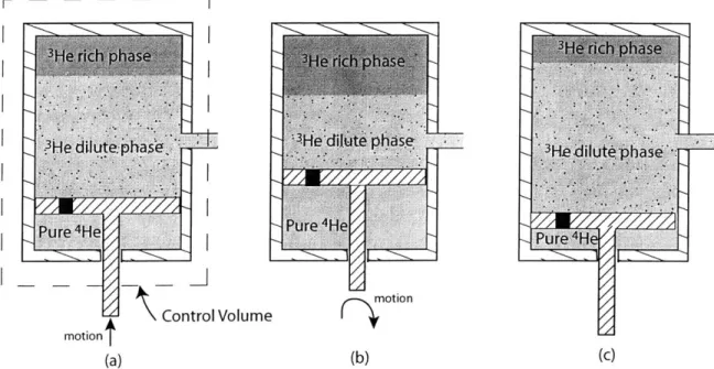
The superfluid Stirling refrigerator does not operate in the two phase region shown in Fig. 1.2. In this region, the mixture separates into a dense dilute 3He-4 He mixture and a less dense concentrated 3He phase. Figure 1.5 shows three "snapshots" of a piston as it "compresses" and "expands" a helium mixture in the two phase region. Using the second law, we will argue that when the low temperature piston operates in the two phase region for the entire cycle, there is no cooling of the low temperature reservoir.
In Fig. 1.5 there is a pure 3He slug floating on top of a dilute phase 3He-4He mixture. We assume this that 3He slug is sufficiently sized to neither disappear nor to entirely fill the low temperature piston during the proposed expansion and compression of the low temperature piston. The 3He-4He mixture in the low temperature piston is connected to a constant pressure reservoir of superfluid 4He through a superleak. Compression of the mixture causes the 3He slug to increase and expansion of the piston causes the 3He slug to
decrease in size. Assuming the temperature and pressure are fixed throughout the
process, the concentration of the dilute 3He-4He mixture doesn't change. We will assume
3He diute phase '-He'dilute 3 phase 3Hee
Pu re4He/
Pure 4He Pure 4
H
motion
motion \ Control Volume
(a) (b) (c)
Figure 1.5: The 3He He mixture in the piston in (a) is in the two phase region. When the fluid is
"compressed" (b), the 3He layer grows and when the fluid is "expanded" (c), the 3He layer decreases.
The dilute 3He phase is the same concentration in (a), (b) and (c).
fluid that enters or exits the expander is always at the same temperature. We apply the second law to the control volume (shown in Fig. 1.5a) around this low temperature piston over a cycle,
IdSc= + jsdN -csdNOUt + Sgen (1.1)
where Scv is the total entropy of the control volume,
Q is the heat transfer into the control
volume, dNin and dNout is the molar flow of mixture into or out of the control volume, s is the entropy per unit mole carried by that flow, T is the temperature of the controlsurface, which by assumption is the same as that of the low temperature reservoir, the fluid in the system, and the fluid entering and exiting the system, and Sgen is the entropy produced in the control volume during the cycle. Since the initial and final states are the same, the net change in entropy over a cycle is zero. The entropy of the mixture can be expressed as a function of the temperature T and concentration x of the mixture [14]. The fluid exiting the control volume is at the same temperature and concentration of the fluid exiting the control volume so sin (x, T)= sou (x, T). The net change in mass in the
system is zero so the net molar flow in equals the net molar flow out, so the entropy entering and exiting the system in Eq. 1 cancel out. Thus, the equation for the heat transfer reduces to
Q
= -TSgen . (1.2)Since T and Sgen are both positive numbers,
Q
must be less than or equal to zero indicating that the compression/expansion process does not lead to cooling of the reservoir when the piston contains a two phase fluid. Note that if our regenerator were not ideal, the temperature of the entering fluid would have been higher than thetemperature of the exiting fluid and thus also the entropy of the fluid entering the system is higher than that of the fluid exiting. A SSR equipped with a non-ideal regenerator would therefore dump more heat into the low temperature reservoir than the ideal regenerator case discussed above.
4He e. 3He-4He
U
Superleak 3HeIn thermal contact with Clearance Clearance In thermal contact with LowTemperature Volume Volume High Temperature
Mass Expansion Regenerator Compression Reservoir
Volume I I Volume
fluid displaced through Regenerator
I)
0h)
isothermal compression
h)
I Ifluid
displaced through Regenerator(31 (3h) (approximately) isothermal expansion (41)14
(40
V( 4h) II QFigure 1.6: A de iction of a Stirling Cycle whose low temperature piston is operating partially in the two
phase region. A He slug develops in the low temperature piston during isothermal compression. This causes significant heat rejection into the low temperature mass during compression. The 3He slug is
dissipated during isothermal expansion. The states of the 3He-4He mixture in the low and high temperature pistons are labeled on the left and right respectively. In Fig. 1.7, these states are mapped on a two phase
We have demonstrated that if the expander of the SSR is operating in the two phase region for its full cycle, it cannot continue to cool its low temperature reservoir. Having shown that a SSR will not cool if the expander piston is operated entirely in the two-phase region, we now wish to consider how the cooling power of the SSR will change as the state of the fluid in the SSR expander approaches and crosses into the two-phase region. We wish to show that an SSR that operates in the two phase region at some part of its cycle, will eventually operate in the two phase region for all its cycle. We will make this argument by considering an SSR with discrete, not sinusoidal, piston motions.
Figure 1.6 depicts the stages of the cycle of an SSR with clearance spaces (volumes not swept by the pistons) in its low and high temperature pistons. As the high temp piston
"compresses" the mixture in the SSR (the process between Fig 1.6.1 to Fig 1.6.2) the concentration in the SSR increases and the heat of compression is largely rejected to the high temperature reservoir. The compression process increases the concentration of
1.0- 0 h4h - - -A (h, 3h) (20,3h) ( 3) superfluid homogeneous mixture E .ool (21,31) (41) "stable" x, 3He Concentration
Figure 1.7: The states of the 3He-4He mixture in the low and high temperature piston are mapped onto a sketch of the phase diagram. The high temperature reservoir holds the high temperature at a constant temperature. The low temperature mass is assumed to drop in temperature as it is cooled. State 2 and 3 are marked by a A, 0, o for successive cycles. The dark line labeled "stable" depicts the states of the 3He-4He mixture in the low temperature piston when operating in the two phase region reduces the cooling power of the low temperature piston to zero. There is no concentration change in the 3He-4He mixture in high temperature piston when the 3He-4He mixture in the low temperature piston is in the two phase region.
the homogeneous fluid in the low temperature clearance volume until the fluid is in the saturated dilute mixture state. With further compression, the mixture in the low
temperature clearance volume phase separates, rejecting the latent heat of the phase change to the low temperature mass. We assume the SSR in Fig 1.6 is operating such that the 3He rich slug goes back into the dilute state during the expansion stroke. The states of the 3He-4He mixture in the low and high temperature piston are shown plotted on a phase diagram in Fig 1.7. The upper left curve in Fig 1.7 represents the states of
the 3He-4He mixture in the high temperature piston. All the states of the 3He-4He mixture
in the high temperature piston are at the same temperature since the piston is connected to a high temperature reservoir. Alternatively, the states of the 3He-4He mixture in the low temperature piston experience a temperature drop as the low temperature mass is cooled. For the small temperature drop in the low temperature mass we consider in Fig 1.7, we model the concentration of the 3He-4He mixture as not changing between cycles in each piston.
As the 3He-4He mixture in the low temperature piston enters the two phase region, heat is rejected to the low temperature mass instead of the high temperature reservoir. The low temperature mass is not cooled until the 3He-4He mixture in the low temperature piston emerges from the two phase region. Because each new state 1I is at the same
concentration of the previous state 11, state 11 of the 3He-4He mixture in the low temperature piston moves into the two phase region. In an ideal SSR with no external head loads or internal dissipations, the 3He-4He mixture in the low temperature piston would eventually run up and down a stable line touching the two phase boundary at one end.
If we accounted for the change in concentration of the 3He-4He mixture in the low temperature piston between cycles, state 11 would converge even faster to the two phase boundary, since the concentration of the mixture in the low temperature piston increases as the low temperature mass gets colder. The new state 11 would be closer to the two phase boundary than the previous state 11.
This analysis demonstrates that once the low temperature piston has crossed into two phase region, the SSR's ability to cool is quickly disabled. There are other issues such as the compromised heat rejection on the high temperature platform, and the high entropy
generation incurred in compressing and expanding the system with a 3He slug that actually make the performance of the two phase working fluid SSR even worse than implied.
1.4 History of the SSR
The first SSR was a single stage device built by Kotsubo and Swift [1] which used a configuration not unlike Fig. 1.4. The regenerator used in this design was an array of 30 CuNi capillary tubes 200 micron in diameter 38 cm in length jacketed in a 3He bath. The
3He bath was chosen as the thermal matrix material for the regenerator because below I
Kelvin 3He is one of the few materials with significant heat capacity. However, the low thermal conductivity of the 3He made it a flawed regenerator material. The SSR had to be operated at very low frequencies, 240 seconds per cycle, to allow time for thermal diffusion into and out of the regenerator's 3He bath. Another undesirable characteristic of
this SSR design is that over time, the operation of the SSR was compromised by a slow diffusion of the 3He atoms across the superleaks. Using 3He_4He mixture concentration of 12% and using a high temperature reservoir of 1.2 K, temperatures around 0.6 K were achieved [2].
The second SSR improved on the first SSR by replacing the 3He bath regenerator with a recuperator design. Two superfluid Stirling refrigerators are placed back to back, their compressors and expanders are connected, respectively, by superleaks as shown in Fig
1.8. 3He-4He mixture fills both sides of the expander and compressor pistons. The regenerator consisted of a counterflow heat exchanger made of 238 CuNi capillary tubes
250 microns in diameter silver soldered in a hexagonally closed pack array with
alternating rows corresponding to each half of the SSR. This SSR was an improvement on the previous design for several reasons. The superfluid 4He reservoirs in the Kotsubo and Swift design is eliminated, each half of the SSR acts as the 4He reservoir for the other. The problem of the slow diffusion of the 3He atoms through the superleaks
disappears since if the two SSR's have been properly loaded, the average concentration on one side of the superleak is the same as that on the other side. In fact, the performance of the two SSR's should improve over time since if there is any initial 3He mass
- ~
Figure 1.8: A representation of a single stage machine consisting of two back-to-back 180 degree out of
phase SSR's exchanging heat through a recuperator.
imbalance between the two SSR's, the slow diffusion of 3He across the superleaks will tend to resolve the imbalance. Also the slow diffusive heat transfer into the 3He bath in the recuperator of the Kotsubo and Swift design is replaced by a more rapid convective heat transfer between the two mass flows in the recuperator of this design. This faster heat transfer mechanism allowed the SSR to be operated at the higher frequency of 20 seconds per cycle. This SSR used a 3He-4He mixture concentration of 6.6%, a piston volume displacement of 0.8 cm3 and a volume of 7 cm3 per SSR half. With a He evaporation refrigerator providing a high temperature reservoir of 1.05 Kelvin, this refrigerator was able to achieve temperatures of 296 mK and net cooling powers of 930
gW at 700 mK and 140 [tW at 500 mK. The same SSR was operated by Watanabe, Swift, and Brisson and achieved a temperature of 168 mK while the high temperature piston was held at 387 mK by a 3He evaporation refrigerator [7,14].
Further improvements of the SSR design involved first a more careful examination of the material used to build the SSR. When designing for performance below I Kelvin, new material properties become important. Designing for efficient heat transfer between two different materials requires considering the Kapitza thermal boundary resistance for
those two materials. Kapitza thermal boundary resistance is defined by Rk = ATQ
where AT is the temperature drop across the interface of two different materials and Q is the heat transfer rate per unit area. At low temperatures this thermal resistance can dominate the heat transfer between two materials. For reasons beyond the scope of this text, the Kapitza thermal boundary resistances between helium and plastics are much
imm N _ ___ - __ - - = % - -11 11 1- - - - - __ - __ bwwk
smaller than that between helium and metals. The next development in superfluid Stirling refrigeration, therefore, was the replacement of the CuNi capillary tubing heat exchanger with a heat exchanger made out of plastic.
A single stage SSR was built by Patel and Brisson that used a heat exchanger
constructed out of a Kapton-epoxy composite material. The heat exchanger consisted of alternating layers of 127 pm thick and 25.4 gm thick Kapton glued together with Stycast
1266. Each 127 ptm layer had five passages 2.38 mm in width and 20 cm long. Small,
medium, and large heat exchangers with a total of 50, 100, and 200 flow passages respectively were constructed by stacking ten, twenty, and forty 127 gm thick layers
respectively. The small, medium, and large recuperators had 1.5 cm3, 2.4 cm3, 6.05, cm3
of recuperative volume per SSR half respectively [16, 17].
This new single stage SSR was a much larger machine than the previously built SSR's. With a large plastic heat exchanger, this SSR had a total volume of 48.3 cm3 per
SSR half and high and low temperature piston volume displacements of 17.7 cm3 and 9.4
cm3 respectively. Using a 3He-4He mixture concentration of 3%, this SSR achieved a
temperature of 291 mK from a high temperature reservoir of 1.0 K, and a net cooling power of 3705 pW at 750 mK, 977 pW at 500 mK and 409 RW at 400mK. The cooling power of this new SSR was a great improvement over the previous SSR's by a factor of 7 at 500 mK and by a factor of 4 at 750 mK [9, 17]
All SSR's constructed until this point were single stage SSR's, meaning one
compressor, one expander. Patel and Brisson hoped to improve on previous performance
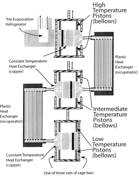
by building a two-stage SSR. This new SSR, depicted in Fig. 1.9, consist of high,
intermediate, and low temperature pistons. The intermediate and low temperature pistons were rigidly connected together so that these pistons moved together. One plastic heat exchanger connects the high and intermediate temperature pistons and another plastic heat exchanger connects the intermediate and low temperature pistons. The best low temperature performance of this new design was achieved while using a large heat
exchanger between the high and intermediate temperature pistons and a medium size heat exchanger between the intermediate and low temperature pistons. The total volume of
Pla He Exc (re
High
Temperature t.I
Pistons
4He Evaporationi(belows)
Refrigerator( l w
PlasticConstant Temperature Heat
Heat Exchanger Exchan
(copper) (recup a ic
Intermediate
hangerTemperature
cuperator) Pistons (bellows) UUM .- Low M~ ,\Temperature e---PistonsConstant Temperature (bellows)
Heat Exchanger (copper)
ger
erator)
One of three sets of cage bars
Figure 1.9: A diagram of the two stage back-to-back SSR design with plastic recuperator.
this SSR was 64.5 cm' per SSR half. The high, intermediate, and low temperature piston volume displacements were 17.7 cm3, 9.4 cm3, and 5.3 cm3 respectively. Using a 3% concentration 3He-4He mixture, this SSR achieved a temperature of 248 mK [10, 17]. The best cooling power performance of this new design was achieved while using a large heat exchanger between both sets of pistons. The volume of the SSR in this configuration was 68 cm3 per SSR half. Although it only achieved a low temperature of
307 mK, the SSR achieved cooling powers of 1 mW at 626 mK, 500 pW at 452 mK and 100 jW at 344 mK [11, 17].
Although the new two-stage SSR achieved a new ultimate low temperature, Patel and Brisson believed that the full potential of this cryostat had not been demonstrated.
from running at full capacity. The SSR is thermally insulated from a 4.2 K liquid 4He
bath by a vacuum. A superfluid 4He leak from the cryostat to the vacuum can, therefore, put a significant additional heat load on the SSR.
The first goal of this work was to resolve the experimental issues of the two-stage SSR built by Patel and Brisson. The second goal was to attempt to improve on previous SSR performances by adding a third SSR stage to the two-stage machine. The details of the machine built are described in Chapter 2. The experimental results of operating both the two and three stage SSR's are presented in Chapter 3.
In addition there are other important technical issues particular to cryostats using moving parts below 1 Kelvin. Chapter 4 presents the result of an experiment to ascertain the heat dissipation due to the flexing and relaxing of the bellows. An understanding of how much heat load on the SSR is due to its moving parts will help us understand the ultimate limitations of this type of refrigeration device.
Due to chemical properties of the 3He-4He mixture, the third SSR stage needed to use a separate working fluid from the rest of the SSR. The analytical and numerical analysis used to explore this issue is presented in Chapter 5.
Chapter 2
Experimental Apparatus
2.1 Description of the three-stage SSR
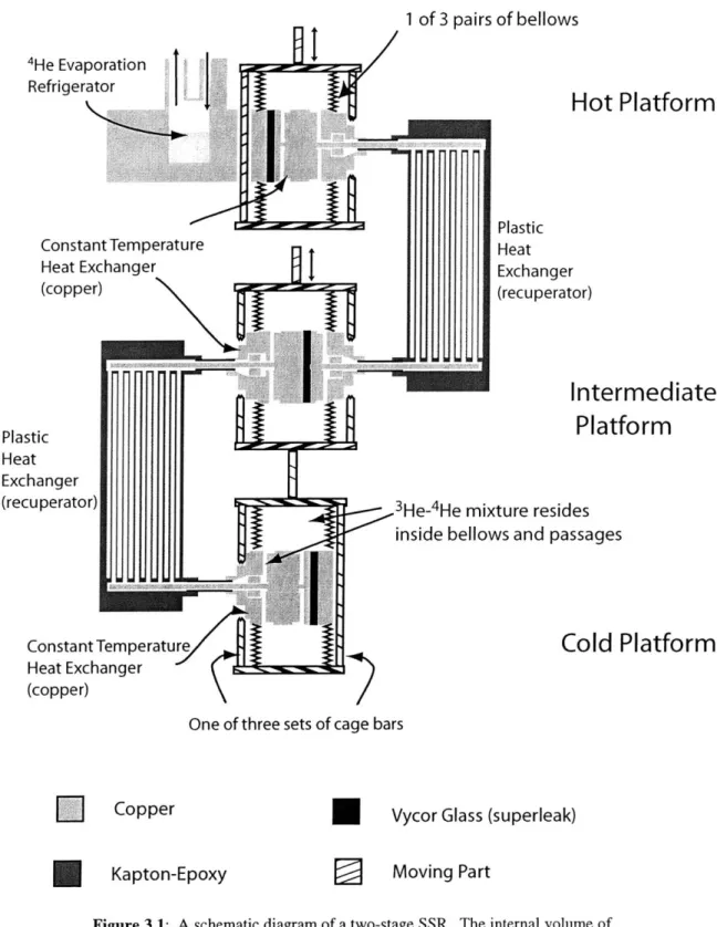
Figure 2.1 shows a schematic of the three-stage SSR. This refrigerator uses the counterflow recuperative configuration, so it has back-to-back SSR's operating 180 degrees out of phase with each other and counterflow recuperators as the regenerators. This SSR consists of four isothermal platforms; the hot, first, and second intermediate and cold platforms are connected by Kapton recuperators are shown in Fig. 2.1. The compressor pistons on the hot platform are held at approximately 1 Kelvin by a 4He evaporation refrigerator. The third stage of the SSR is thermally connected to the second stage of the SSR on the second intermediate platform, but third stage is filled separately and the 3He-4He mixture cannot flow between the third stage and the second stage.
The hot, first intermediate and second intermediate, and the cold platform of the SSR are made of solid blocks of OFHC copper on which the pistons are mounted. The pistons are made with edge welded stainless steel bellows, which have convolutions that nest into one another to minimize void volume. The effective areas of the pistons based on the manufacturer's specifications [18] are 17.74 cm 2 for the hot platform pistons, 13.61 cm2
for the first intermediate platform pistons, 7.68 cm2 for the second intermediate platform
4 He Expa Refrigera econd tage 1 of 3 Kapton-Epoxy Composite Heat Exchangers Second Intermediate Platform
Stan fne low temperature valves
void spaces
Out in
nsion
tor Hot Platform
First
jIntermiediate
Platform
3rd Stage SSR
Ifill
lineslow temperature valves
1 of 5 Bellows Sets
Cold Platform
Copper
Kapton-Epoxy
Vycor Glass (superleak)
D
Moving Part
3
He-4He Mixture
Figure 2.1: A schematic of the three-stage superfluid Stirling refrigerator.
for the cold platform. The hot platform pistons are rigidly connected together and driven sinusoidally using a push rod from a room temperature drive. The first-intermediate-platform and second-intermediate-first-intermediate-platform second-stage pistons are similarly connected and driven together using a common push rod. The second-intermediate-platform third-stage pistons and cold platform pistons are also respectively rigidly connected and are
First tage Third Stage
U
U
independently driven by two push rods actuated from room temperature. The hot
platform temperature is pinned at approximately 1.0 K by a 4He evaporation refrigerator. Within each piston platform, there are superleaks made from porous Vycor glass, which allow the superfluid 3He-4He to flow freely between the halves of the SSR during
operation. In the hot platform, the superleaks are three Vycor cylinders 6.03 cylinders in length with diameters of 1.39 cm, 1.35 cm, and 0.72 cm. In the first intermediate
platform, the superleaks are three Vycor cylinders 10.63 cm in length with diameters of 0.74 cm. In the second intermediate platform (second stage), the superleaks are three Vycor cylinders 15.16 cm in length with diameters of 0.74 cm. On the second
intermediate platform (third stage) the superleaks are four Vycor cylinders 13.09 cm in length with diameters of 0.74 cm. On the cold platform, the superleaks are three Vycor cylinders 12.06 cm in length with diameters of 0.73 cm. The total volume of the Vycor glass in the first and second stage of the SSR is 53.2 cm3. The total volume of the Vycor
glass in the third stage is 21.9 cm3. Since 28% of the Vycor glass is void space [19], the
glass contributes 15 cm3 to the 3He-4He mixture volume of the first and second stage of
the SSR and 6.1 cm3 to the 3He-4He mixture volume of the third stage. The 3He that diffuses into this volume does not participate in the operation of SSR.
Within each piston platform, there are also isothermal heat exchangers made from nested OFHC copper cylinders press fit into the piston platforms. A 76 pm gap exists between the inner walls of an outer cylinder and outer walls of an inner cylinder. At the top of each cylinder is a flow distributor 0.635 mm deep and 0.317 cm wide around the cylinder circumference. Each half of the hot piston platform contains one cylinder 2.14 cm in length with a diameter of 3.80 cm, which provides a total heat transfer area of 65.94 cm2 . Each half of the first intermediate platform contains two cylinders that provide a total heat transfer area of 209.70 cm2. The first cylinder is 3.97 cm in length
with a 4.11 cm diameter while the second cylinder is 4.88 cm in length with a 3.52 cm diameter. Each half of the second intermediate (first and second stage) platform contains four cylinders 6.07 cm in length providing a total heat transfer area of 276.6 cm2. The
diameters of the cylinders are 4.43 cm, 3.91 cm, 3.39 cm, and 2.88 cm respectively. Each half of the second intermediate (third stage) platform contains four cylinders 5.02 cm in length providing a total heat transfer area of 257.4 cm2. The diameters of the four
25 /pm Kapton
127 pm Kapton
o :>
I
A
Flow through recuperator of SSR half #1
Flow through recuperator of SSR half #2
Figure 2.2: The arrangement of alternate layers of Kapton templates within the recuperator to
form a counterflow heat exchanger. The flow of opposite halves of the SSR alternate between successive layers of the 127 gm Kapton sheets.
cylinders are 4.94 cm, 4.43 cm, 3.79 cm, and 3.16 cm respectively. Each half of the cold piston platform has seven cylinders 4.77 cm in length providing a total heat transfer area of 379.5 cm2 . The diameters of the seven cylinders are 5.83 cm, 5.32 cm, 4.82 cm, 4.30 cm, 3.80 cm, 3.29 cm, and 2.78 cm respectively.
The recuperators, shown in Fig. 2.2, used in this SSR are of a plastic design type constructed and built by Patel [16]. The recuperative portion consists of alternating layers of 127 km Kapton film and 25.4 ptm Kapton film [25] glued together using Stycast
1266 [20]. Each 127 pm layer has five passages 2.38 mm in width and 20 cm in length.
The recuperators from the hot platform to the first intermediate and from the first
intermediate to the second intermediate platforms (first and second stages of the SSR) are large recuperators with forty 127 gm layers and thirty-nine 25.4 pm layers. Each large recuperator has a total volume of 20.9 cm3, of which 12.1 cm3 (6.05 cm3 per SSR half) is
dedicated to recuperative heat transfer. The recuperator from the second intermediate to the cold platform is a small recuperator with ten 127 gm layers and nine 25.4 gm layers. The total volume of the small recuperator is 11.10 cm3, of which 3.02 cm3 (1.51 cm3 per
As can be seen in Fig. 2.1, a total of four fill lines run from room temperature to the SSR. The two fill lines to the two halves of the first and second stage SSR are designed to be sealed at low temperature by valves mounted on the hot platform. These valves are actuated manually from room temperature and prevent the 3He-4He from moving up and down the fill capillaries during operation of the SSR.
The two fill lines into each of the SSR halves of the third stage are sealed at low temperature by valves mounted on the 300 mK platform. The valves are also actuated manually from room temperature and also act to prevent the 3He-4He mixture from moving up and down the fill capillaries during operation of the SSR. These valves were designed and tested to be superfluid tight in case it became necessary to pump out the fill lines to prevent heat loss. As the third stage SSR is thermally isolated from the 4He
evaporation refrigerator (the hot platform), the fill lines are wrapped around the 4He evaporation refrigerator so that the third stage's 3He_ He working fluid can be liquified during loading.
Calibrated ruthenium oxide [21] and germanium [22] and carbon resistor thermometers mounted on the outside of the piston platform are used to monitor the temperature. The uncertainty of our temperature measurements are + 0.67 mK at 1.0 K and + 1.02 mK at
350 mK. Cooling powers are measured by monitoring the voltage across and current
through a heater made of wound manganin wire. The uncertainty of our cooling power
measurements is ± 2 pW.
The total volumes of the SSR's are given minus the void spaces and the volume of the
fill lines because these volumes are inactive during the operation of the SSR. The total
volume of the first and second stage is 136 cm3. The total volume of the third stage SSR
is 103.3 cm3.
2.2
Development of the Patel and Brisson SSR
The first and second stage of the SSR were designed and built by Ashok Patel. The major sections of the third stage were also designed and built by Patel but finished and assembled in this work. The following sections will delineate three alterations to Patel's design. The first section is an alteration made to plastic recuperators. The second and
third sections are design choices made in the third stage to prevent a thermal linkage between the third stage and the first and second stage of the SSR.
2.2.1 Heat Exchangers
The plastic heat exchangers consist of a copper header silver soldered to stainless steel tubes that then sealed to the plastic body of heat exchanger using epoxy. The header consists of two machined pieces of OFHC copper, as shown in Fig 2.3, that were in turn sealed together with an indium o-ring. The outer piece of the metal header is designed to mate with specific copper heat exchangers on the SSR itself and by breaking the indium seal and replacing the outer piece, the heat exchanger could be put into different positions in the SSR.
The problem with this design was that the procedure of silver soldering the stainless steel tubes to the inner copper header piece caused the copper to anneal. The
compressive forces required to make the indium seal between inner and outer header piece would plastically deform the inner head piece and, over time, compromise the indium seal. Fixing this problem required breaking the seal, filing the copper surfaces flat, and remaking the indium seal.
This unreliable sealing method was replaced with an improved method developed specifically for these joints. All of the indium seals between the inner and outer header pieces were replaced by a Stycast 1266 epoxy seal. To prevent cracking in the epoxy, the epoxy is allowed to cure under no compressive force. When mounted on the SSR the epoxy is put into compression by the through bolts in the flange. This compressed epoxy joint remained superfluid tight over repeated thermal cycles.
The drawback to using the epoxy seal is if a crack develops in the seal, the copper flanges must be broken apart, carefully cleaned and resealed. Performing this procedure causes the heat exchanger to endure physical stresses and risks damage to the rest of the heat exchanger. Also, the ability to change flanges between the different heat exchangers is lost and thus move different heat exchangers to different positions.
3E 0 E- . LI -- AW Seal To Pistons - -Outer Metal Header Piece (OFHC copper)
Kapton-Epoxy Heat Exchanger
Inner Metal Header Piece
(OFHC copper)
Silver Solder Joint
To Pistons
Epoxy Joint Stainless Steel
Tubes
MIT Libraries
Document Services Room 14-0551 77 Massachusetts Avenue Cambridge, MA 02139 Ph: 617.253.2800 Email: [email protected] http://libraries-mit.edu/docsDISCLAIMER OF QUALITY
Due to the condition of the original material, there are unavoidable flaws in this reproduction. We have made every effort possible to provide you with the best copy available. If you are dissatisfied with this product and find it unusable, please contact Document Services as soon as possible.
Thank you.
The Archives copy is missing page 34.
This is the most complete version available.
I
cage bar Fill Lin 4 to SSR shaft to room temperaturewhere actuated
LII
Brass
t S5 Stainless Steel
Threads
Bearing
s- Bellows soldered
with lead-tin to Bras and Steel
es - stainless steel tip
polished to 1 /. m finis
sharp edge machined in brass
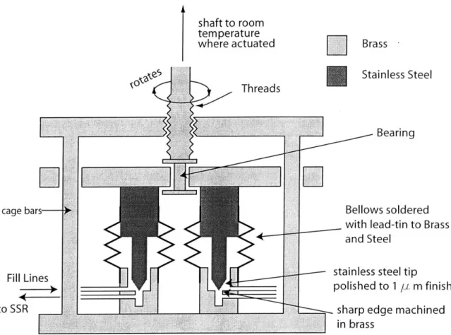
Figure 2.4: A schematic of the dual superfluid tight valves.
2.3.1 Third-Stage Valves
The first method discussed to prevent the superfluid 4He from putting a heat load on the third stage was evacuating the fill lines completely after the SSR has been filled. In order to prevent the superfluid 4He in the third stage from flowing in and out of the evacuated fill lines during expansion and compression, the valves between the pistons and the fill lines need to be superfluid tight. Fig. 2.4 is a schematic diagram of the dual valves that were designed, constructed, and successfully tested to be superfluid tight.
The valve set was designed to allow two flow lines to be closed by the rotation of a shaft, which is actuated at room temperature. The important components of the valve set are the stainless steel valve stem that has been highly polished to a 1 micron finish in a conical region and the brass seat machined with a sharp corner edge [23]. The seal is
S
created by the contact between the polished section of the valve stem and the sharp edge of the brass seat. The valve stem is pressed into the brass seat by rotating the actuating
shaft. Bellows soldered with lead tin solder to the valve stem base and brass seat seal the
body of the valve.
The bearing referred to in Fig. 2.4 is a simple stainless steel sleeve over the rotating shaft. Unlike the design this valve set was based on [23], it does not require a special bearing between the actuating shaft and the valve stem to prevent a torque from being placed on the valve stem. This because the two valve stems are attached to a brass plate that slides up and down on a set of cage bars, inhibiting any rotational movement of the valve stems.
This valve set also includes a positive withdrawal system. The brass plate which controls the opening and closing of the valve stems can be pushed (valves closed) or pulled (valves opened) by the rotating shaft.
This valve set was tested by filling it with superfluid 4He at 1.2 Kelvin and found to be superfluid tight.
2.3.2 Void Space Analysis
The alternative method of preventing the thermal link between the 4He expansion refrigerator and the second intermediate platform was to design void spaces thermally connected to the hot platform. The theory behind adding void spaces to the fill lines and the analysis to choose their volume follows.
As discussed earlier, the high thermal conductivity of pure 4He is due to the unimpeded motion of the superfluid and the normal fluid counterflow. A superfluid moves to the hot end of the container where it is converted to a normal fluid particle by absorbing thermal energy from the hot end. The normal fluid particle is then displaced away from the hot end by other superfluid particles towards the cold end. At the cold end, the normal particle (a phonon-roton excitation) is converted back to a superfluid particle by rejecting thermal energy to the low temperature end of the container. There is little interaction between the superfluid and the normal particle as they flow past each other.
3 He-4He mixture Vhot O 0 0 0 0 0 00 000 00 0 00 0
0
0
00
0
D 0 0 0 0 0 00~ 0 'hot 0 0 0 0 Thot 00 0El00 0 0 000 0000 00 0 000000 0 0 0 0 Vcold1o0 Thot 000 Tcold
00 Phonon-roton particles 0 03He particles
Figure 2.5: On the left, a container at a hot temperature is loaded with 3He-4He mixture. On the
right, the volume on the bottom has been brought to a cold temperature. Few phonon-roton particles exist at this temperature. The 3He particles are flushed into this cold volume and are just sufficient to
balance the pressure of phonon-roton "particles" at high temperature. Note that the 3He particles are conserved while the phonon-roton particles are not.
In 3He-4He mixtures, however, the 3He component of the mixture is viscously locked to the viscous normal component of the 4He, the phonon and roton excitations in the 4He component of the mixture. If a 3He-4He mixture is placed in a container with a
temperature gradient the superfluid counterflow currents will begin to flow. The normal fluid particles will carry 3He particles to the low temperature end of the container until the concentration of the 3He component is high enough to counter and stop the flow of the normal component (and hence, the superfluid component flow too.)
If the temperature gradient in the container is too large or the initial 3He concentration of the 3He_ He mixture is too low a condition known as "heat flush" will occur in the mixture. Heat flush occurs when all the 3He is flushed to one end of the container leaving a portion of the container filled with a region of "pure" 4He. The pure region is a region of high thermal conductivity in the fluid. This condition can be prevented from occurring in the fill capillary by choosing the geometry shown in Fig 2.5.
The distribution of 3He in the capillary tube can be determined using the phonon-roton
gas model [24] for the normal component of the 4He and the Boltzmann gas model for the