HAL Id: insu-02270098
https://hal-insu.archives-ouvertes.fr/insu-02270098
Submitted on 23 Aug 2019HAL is a multi-disciplinary open access
archive for the deposit and dissemination of sci-entific research documents, whether they are pub-lished or not. The documents may come from teaching and research institutions in France or abroad, or from public or private research centers.
L’archive ouverte pluridisciplinaire HAL, est destinée au dépôt et à la diffusion de documents scientifiques de niveau recherche, publiés ou non, émanant des établissements d’enseignement et de recherche français ou étrangers, des laboratoires publics ou privés.
Technology evolution of aircraft simulator for real
equipments validation
Jean-Marie Calluaud, Jean Casteres, Stéphane Gaudaire
To cite this version:
Jean-Marie Calluaud, Jean Casteres, Stéphane Gaudaire. Technology evolution of aircraft simulator for real equipments validation. Embedded Real Time Software and Systems (ERTS2008), Jan 2008, toulouse, France. �insu-02270098�
Technology evolution of aircraft simulator for real equipments
validation
Jean-Marie CALLUAUD, Jean CASTERES, Stéphane GAUDAIRE
Airbus France 316 Route de Bayonne F-31060 Toulouse Cedex 9
Abstract:
Aircraft systems have increased in number and complexity since 1985. The integration test rig, often known as the “iron bird” integration simulator, has been developed to assemble and test as many as possible of the various aircraft systems in a simulated environment.
The integration simulator aims at:
• Simulating the aircraft environment, the natural flight loop and certain systems
• Stimulating the real aircraft equipment The evolution, in the last twenty years, of simulators for aircraft equipment validation is presented in this article.
From 1995 to 2008, integration simulator architecture has taken various evolutionary steps that have affected:
• Simulation complexity • Simulation architecture • Technology used
The article shows how mass-market technology (hardware, communication, bus, operating system) can fit into the specific and complex architecture of the integration simulator. The multiple technical and industrial constraints that must be taken into account to migrate from specific to generic solution will be presented.
Keywords: Simulation, real time, operating system
1. Introduction
Simulation, in today’s complex systems, plays an increasing role. The aircraft industry has been one of the earliest users of the simulation techniques and is still paving the way for the adoption of new technologies.
The complexity of systems has increased the cost of their development and simulation is often a way to reduce the costs of testing aircraft complex systems. We have developed a chain of simulation platforms ranging from the research simulator to the integration test rig to support the aircraft program. The aerospace industry vision is that embedded systems will be key differentiators in the aircraft business. But this embedded systems industry is
gaming). These products display a different production pace which creates a difficult obsolescence problem for the other industries. Focus must be put on architecture methods and development tools to adjust to this pace, with each industry contributing its know-how for cost reduction: automotive with large scale production cost savings and aerospace for safety and quality control.
This article will present how the steps to adapt to this new market conditions have taken place; and how the integration test rig is now ready to adapt to the fast pace of change of the mass market.
We will first look at the simulation chain implemented to answer the aircraft program simulation needs. An analysis of the evolution of the architecture for the integration simulator and of its real time performance profile will be presented in several steps: the initial specific architecture, the first evolutions to standard operating system, and finally highlighting the mass market technology adoption.
2. Simulation Platform Needs
An aircraft is a complex system that involves different knowledge domains such as: aerodynamics, engines, electric and hydraulic systems, flight dynamics. In order to validate new ideas and new technologies in these various domains, a series of simulation platform has been built. This chain covers the prospective research simulator (EPOPEE), the development simulators (A/C-1 and desktop simulators) and the integration simulator A/C-0. These simulators support the aircraft development from 5 years, 2.5 years and one year before the first flight respectively.
In this article we will focus on the integration simulator: aircraft 0 or A/C-0 (or “iron bird” integration test rig) that enters into service one year before the program’s first flight.
The iron bird integration concept dates back to the Concorde program: compatibility checking between various aircraft systems can be performed at a lower cost on the ground [1]. The integration test rig tests, verifies and validates the compatibility between real aircraft systems, as they will be assembled onto the aircraft with a pilot in the loop. As a consequence, an important characteristic of the integration simulator is that it shall perform simulation in real time since it
needs to stimulate real avionics equipments and interface with a real pilot.
A/C-0 is used to prepare the first flight but also to participate in aircraft certification, and remains operational throughout the aircraft program lifecycle. The integration test rig comprises of two main components: the simulated world environment and the real equipment that needs to be integrated. These are:
• Aircraft equipment such as: flight controls, flight warning systems and aircraft communication networks, avionics bays
• Cockpit systems such as: integrated cockpit panels, cockpit display systems
• Aircraft electrical power generation system • The “iron bird” which is constructed using
the hydraulic, electrical and flight control actuators from the aircraft.
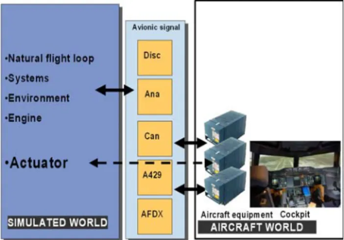
Figure 1: Basic elements of integration simulator In order to perform the integration of these elements a simulated world environment is developed. The integration simulator embeds the required simulation computing capacity to be able to model the natural flight loop, the engines, the aircraft environment as well as other missing systems. The simulator also supports the communication between the simulated to the real systems worlds via an interface. The interface samples and synthesizes the various aircraft signals necessary for the simulation: analog, digital, ARINC 429, CAN and AFDX signals.
Figure 2: Aircraft 0 simulator
The aircraft 0 integration simulator must support a fundamental need for the integration step: the ability to be reconfigured between simulated and real equipment. We illustrate this feature with the following representative example of the aircraft Electrical Flight Command System. When connected to the Iron bird test bench, the integration simulator directly drives the aircraft actuators present on the test bench; when the integration simulation is not connected to the iron bird, but only to the avionic bay, a simulation of the actuator loop is required.
3. Specific Integration Simulator Architecture
In 1987 the A320 makes its first flight. The program is very important for Airbus since it introduces fly-by-wire flight controls to the industry. At the time, the computing means are far more limited than those we know today: this limits the ambitions and needs covered by the simulation. The integration simulation is based on a real time loop at 40 milliseconds for the flight loop, and 80 ms for the other models. On the interfaces, the sampling of the input and output is performed at 20 milliseconds, while outputs that require this refresh rate are computed using extrapolation methods.
Since the integration simulator needs to test as many as possible of the real aircraft equipments, these have to be “stimulated” as they arrive on the test rig. Stimulation of aircraft equipment can be defined as the art of communicating with the systems without going to a full range functional model. For example, aircraft flight command actuators were simulated using recorded tables. In the following table, we give a view on the number of models involved in the simulation: this gives an idea of the number of simulated models and stimulated elements, as well as the required processing power (CPU).
We will use the A320 program integration simulator as a reference throughout this article for CPU power and data exchange throughput. Additionally the number of data signals indicates the volume of exchanges at the interface level.
Table 1: simulation size
In the early days of the A320 development program, there were only proprietary solutions for computers, operating systems and I/O acquisition buses. The integration simulators were built around these solutions, before the appearance of Unix workstation and Ethernet a few years later.
The next aircraft program is the A340 in 1989 and the program allows bringing new technology to the integration simulator. The VME bus is available and enables an easy “on demand” addition of IO boards to the interface bays. Reflective memory technology fulfils the new processing power requirements whilst keeping existing software developments.
The integration simulator architecture at that time was built on computers connected to each other
using reflective memory. These computers were running proprietary operating systems driving avionic signals IO acquisition boards that had been developed in-house. At this time, the timing reference for the simulation was the 50 Hz coming from the power grid.
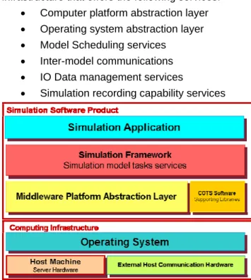
The real time software principles, that are still valid today, were already present: simulation models needed to be scheduled. Simulation models are therefore controlled within a real time simulator infrastructure that offers the following services:
• Computer platform abstraction layer • Operating system abstraction layer • Model Scheduling services
• Inter-model communications • IO Data management services
• Simulation recording capability services
Figure 4: Simulator software architecture With such architectures, the real time performance profile were:
• Model scheduling at 40 ms +/- 1 ms • IO sampling/synthesis 20ms +/- 1ms
4. A first step towards the standards
In 1998, the A340-500/600 program brings a new wave of requirements. These require filling of a new technology gap for the integration simulator.
The new requirements demand that flight commands be validated while modelling the aircraft structure dynamic behaviour. Other models gained in the level of detail that could be modelled for example: the transients for slat/flaps and gears, ground reaction and runway topology, as well as dynamic modelling of the fuel displacement while the aircraft was in motion. These needs will all contribute to increase the accuracy level of the simulation and trigger the use of new tools and methods: for example code generation. The program will also be the first one to test the integration of a functional simulation model
delivered by another partner, in the case of the FUEL model.
The validation of flight controls in the context of aircraft dynamic structure behaviour requires:
• A new aircraft dynamic structure modelling and a IO sampling rate at 10ms
• New aircraft flight control actuator simulation control loop at 5ms
At this time two new technologies were used for the development simulators as well as the integration simulators:
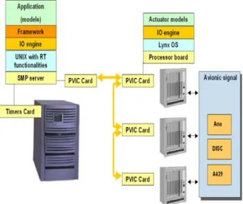
• Symmetric Multi-Processor SMP • Versatile Module European Bus or VME Both technologies will bring benefits to the integration simulator and introduce two main path to real-time solutions.
Figure 5: A340-600 simulator architecture The SMP server architecture uses a general purpose UNIX operating system (GPOS). This operating systems brings two fundamental capabilities:
• Pre-emptive process scheduling • Deterministic timer driven events
The VMEbus utilization introduces the controlling CPU board. This CPU, closer to the acquisition interface, runs its own smaller Real Time Operating System, RTOS (Lynx OS), often called hard real time capable OS, yielding deterministic response time on the CPU board.
The GPOS brings a wide software base, while the RTOS focuses on strict deterministic real-time. The integration architecture for the program will finally be a mix of both technologies: an SMP host will handle the models for all the simulations and a VME bus rack will drive the IO cards. The link between the SMP host and the VME rack CPU head is a proprietary solution.
A dedicated CPU card and its RTOS perform the inner control loop, in charge of the flight command actuator simulation.
With this architecture the real-time performance profiles are:
• SMP Host scheduling: 10 ms +/- 200µs • Interface scheduling: 5ms +/- 50µs
Looking back at this technology step, one of the main benefits was to be able to migrate the simulation infrastructure to a standard host equipment, and benefit from the international standardization efforts conducted on UNIX, that would soon become POSIX. The VMEbus was also a step in that direction but with still a relatively small RTOS audience at the time.
Additionally, another lesson still true today was the trend and need for more accurate and high fidelity simulations, that would require more computing power.
5. Evolution to standard maturity
The A380 program brought the simulation world to the forefront. The breakthroughs achieved on the aircraft systems side as well as the structural size of the airplane required simulations on every step of the way from the design to the first flight.
Integration of models coming from partners was extensively used. These models were required to run at 40 ms, and, as a consequence the simulation flight loop had to be executed in 10ms.
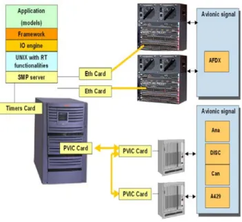
Last but not least were the new aircraft onboard communication needs. The program introduced two new buses and associated protocols: CAN and AFDX. The avionic data communication network ADCN, standardized in ARINC 664, defines the avionic full duplex switched Ethernet as the communication protocol, which adds a simulation requirement on the integration simulator. The 50 registered end systems represent 570 frames (30 frames per 8 milliseconds) and 50000 digital numeric values to be handled by the simulation.
These technology introductions onboard the aircraft increase the CPU power and inter-model communication needed by the simulation:
Table 2: A380 simulation sizing
The integration simulator architecture had to take into account these new requirements and investigate new techniques to bring additional benefits. PC based distributed architecture was envisaged, but abandoned since the performance at the time did not meet the requirements.
One can insist on a key point that helped the SMP quad CPU staying at the heart of the integration simulator architecture. These UNIX based architectures took benefit of the microprocessor war involving major manufacturers such as Intel, Motorola, Mips or SUN. These architectures improved dramatically over the years from the CPU clock speed point of view but also from the inter processor communication standpoint. This allowed the SMP platform to cope with the increased level of accuracy required for the models. The SPEC benchmarks (Standard Performance Evaluation Benchmark), one of the most successful attempts to create a standardized benchmark application suite [2], helps represent the integration simulator application to predict if a platform would be appropriate for a given simulation.
Figure 6: A380 simulator architecture
As for the required performance for the flight command control loop, the A380 program required an increase of 10 times the performance, but there too the CPU power increase available on the board was enough.
The Ethernet had made it into the aircraft with AFDX and since the host was easily capable of managing Ethernet connections, it was very natural to connect directly connected to the ADCN aircraft switches. At the same time, one of the interfaces dedicated to cockpit digital input acquisition had become obsolete and a solution was developed in Airbus that also used Ethernet connections from the host to the interface.
Figure 7: A400M simulator architecture
With this architecture the real-time performance profiles are:
• SMP Host scheduling: 10 ms +/- 200µs • Interface scheduling: 2,5ms +/- 50µs
6. Linux Mass Market Technology
For the first time in this small history, the next step came from the computer industry and not from an aircraft program. It pushed us to go for the next technology gap. The servers we were relying on, were announced to be obsolete by 2008. At the time, the micro-processor gap was so big that from the SPECfp_rate on SPECint_rate analysis the PC generation could outperform the machine we were using by two orders of magnitude or more.
In parallel, the Linux operating system had matured in the UNIX industry. It was no longer a pet project and was supported by major distribution companies (such as Red Hat or SUSE). The operating system was following the POSIX international standardization effort, and would be a more natural migration for our teams.
Another major advantage in the modern open source operating system was the multi-media capabilities that were making their way into the mainstream PC world. Modern Internet connections had raised the need for audio and video capabilities at home. Voice over IP was shaking the plain old telephone system business model, and the Linux operating system was pioneering ways to support these features thanks to its very active community.
Multi media codex used for the recent Internet applications turned out to have real time requirements that triggered an effort in the Internet community to put new improved real time handling capabilities in the kernel. This initiative was known as the Linux PreemptRT kernel [3]. At the same time chip manufacturers were converging on the hardware modules at the periphery of the microprocessor cores that would handle the management of time and interrupts on the chip (Local Advanced Programmable Interrupt Controller [4]). Time management for the simulation application would rely on the newly adopted microprocessor chip standards. Little by little, fundamental patches dealing with the way the interrupts are managed and the way the priorities are handled made it to the mainline kernel source code trunk. Because of this evolution Linux PreempRT was selected for the simulation host.
The process is the executing instance of a program [5] (the word “task” is used as a synonym). A process has a unique identification number and a priority is associated to that number. The operation of suspending a process and inserting it into the ready queue is called pre-emption [6]. The scheduling policy of the kernel selects the next process to run based on the priority number. This allows a high priority process to take the CPU if its priority number allows it. The scheduling policy algorithm computes process priority as explained in [6].
This mechanism was introduced in the Linux kernel, in the recent versions of the kernel, in a homogenous manner for all processes. Together with the architecture of timers on the new processor chips it allowed Linux developers to implement a pre-emptive version of the operating system.
Figure 8: Monta Vista Fostem 2006
In parallel, Linux co-kernel simulation became available on the market more widely, with the ability to run an RTOS. For a tighter real time application this solution was selected as a good candidate for the control loops.
The main selection for the simulation host Pre-empt RT Linux solution raised a fundamental product life cycle dilemma. In order to ensure the long term support for a Linux based solution through the long life of the integration simulator three options were envisaged:
• Internal development: we are in charge of the operating system and hardware, we experiment the integration choices. We assume responsibility for the entire operating system package integration.
• Market expert: we select a complete real-time packaged solution from the catalogue of a manufacturer.
• Integrated service: we select an architect consulting company that architects with us, on our recommendations, a real-time solution and is responsible for the package. The third path was agreed on and the integrated service defined. This choice proved to be the correct one: since then, major commercial companies involved in the distribution of Linux have decided to look into this technology. Recent announcements confirm their interest [7]
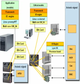
The integration simulator architecture selected was based on multi-core mainstream PC architectures. Ethernet link, with an adequate network topology were selected to connect to the VME equipment performing the interface functions for traditional and AFDX IO. This architecture is being retrofitted to the in_service aircraft simulator of the department.
The paradigms and formalism used for the specifications of complex aircraft systems have witnessed significant progress in the recent years, and benefit today from recent improvements in automated code generation. This fact together with the increase in the model precision and broader use
of simulation in every aircraft’s system will constitute the main driver for our future investigations.
Figure 9:new simulator architecture.
These new tools and environments require more computing infrastructure performance, while modelling precision will require tighter real time control loops. Distributed simulation, pre-emptive kernel performance and co-kernel simulations are the lines on which we should be able to draw a solution for our future needs.
Figure 10: architecture forecast
Another constraint that Linux helped us withstand was to share binary compatible models for all our simulation platforms.
7. Conclusion
Architecture choice for an industrial product such as the integration simulator is constrained by the technology solutions available on the market.
In the past 20 years we have moved, with some difficulties, from a proprietary technology to a standard set of technologies. And today, we have been able to architect industrial solutions around available mass-market technology.
The transition from a Unix based solution to a Linux mass market PC architecture did not trigger an expensive software migration, and this step is economically sound.
Mass-market solutions are moving fast, but this continuous move guaranties the flexibility and versatility of our solutions. Monitoring this continuous move represents a manageable effort, and allows the freedom to select the pace at which new technology is introduced in the product.
Simulation is more and more used as a validation tool. Representative and precise models will set the rule for the requirements requested of the integration simulator architecture and computing infrastructures associated.
Architecture for aircraft simulators is a fantastic domain to explore: there are always new ways to investigate and new questions to ask. VME architecture, for example, will need to be revisited and it is our challenge to look at the emerging technology that will fulfil our needs.
Virtual machines today, may not offer real time performance that our integration simulator is aiming at. But product life cycle management schemes that the virtualization enables, as well as ease of migration and third party partner hosting are certainly advantages and we shall periodically revisit the performance of this technology.
Lastly, modelling the simulator and abstracting the simulation application from the hardware and the software it runs would allow us to define the architecture of the simulator based on the application it is simulating. The emergence of a formalism in this domain would open the possibility of simulation as a whole.
The completeness and functional possibilities of the recent models developed for simulation are set to demonstrate the tremendous help that simulation already brings today to the industry. Technology available in the industry allows following the ever-increasing level of precision required in the simulation environment.
Our objective will be to look at these new technologies and see how they can serve our goal of providing high fidelity real time simulation for aircraft systems.
8. Acknowledgement
The work described in this paper is a team effort of the simulation team in our company and partners. All the individuals of the team as well as additional experts contributed to the success. Thanks to you all.
9. References
[1] C. Coureau, D. Liot, B. Mattos, « Airbus Engineering Simulation Methods – Past and Future Trends », p5, §5, 2004
[2] John L. Hennessy, David A. Patterson, “Computing Architecture: A quantitative Approach”, Third Edition, Morgan Kaufmann, p28, 2003
[3] http://rt.wiki.kernel.org/index.php/Main_Page
[4] Intel, « Intel 64 and IA-32 Architectures Software
Developer's Manuals”
http://developer.intel.com/products/processor/manu als/index.htm:
[5] W. Richard Stevens, “Advanced Programming in The Unix Environment”, Addison-Wesley, 1993 [6] Giorgio, C. Buttazzo, “Hard Real-Time Computing
Sysyems: Predictable Scheduling Algorithms and Applications”, Kluwer Academic Publisher, 1997 [7] http://linuxfr.org/2007/12/13/23447.html “la guerre
du temps réel”
10. Glossary
AFDX: Aircraft Full DupleX CAN: Controller Area Network
GPOS: General Purpose Operating System RTOS: Real Time Operating System SMP: Symmetric MultiProcessing VME: Versa Module Eurocard