Configurator: A Configuration Program
for Satellite Dish Hardware
by
Mark Paul Hurst
S.B., Massachusetts Institute of Technology (1994)
Submitted to the Department of Electrical Engineering and Computer Science in partial
fulfillment of the requirements for the degree of
Master of Science in Computer Science and Engineering
at the
MASSACHUSETTS INSTITUTE OF TECHNOLOGY
May 1995© Mark P. Hurst, MCMXCV. All rights reserved.
The author hereby grants to MIT permission to reproduce and to distribute copies of this
thesis document in whole or in part.
Author
Department of Electrical Engineering and Computer Science
Jan 27, 1995Certified by
Professor M. Frans Kaashoek
Thesis supervisor
Certified by
A,
Mike J. Skeith
Assistant Vice President, Hughes Network Systems
Company supervisor
Certified by
/P}ofessor
Frederic R. Morgenthaler
Committee on Graduate Students
MASSACHUSETTS INSTITUTE OF TECHNOLOGY
Configurator: A Configuration Program
for Satellite Dish Hardware
by
Mark Paul Hurst
Submitted to the Department of Electrical Engineering and Computer Science
on January 27, 1995, in partial fulfillment of the requirements for the degree of
Master of Science in Computer Science and Engineering
Installation of satellite dishes requires certain procedures to be run on the communications hardware. The installer uses a configuration program from a PC to perform these procedures. The configuration program send commands to the target hardware through a serial port to read and write locations in target memory. In addition to setting configuration parameters, some monitor and control functions may be run.
This thesis describes the Configurator, a configuration program which replaces the ones used pre-viously by installers. The user interfaces of previous configuration programs were text-based and poorly designed. The Configurator allows installers to configure different targets with a consistent, well-design graphical user interface. The Configurator offers installers additional features, such as specialized calculation screens.
The code of the Configurator is designed such that periodic updates (to account for changing targets) are easy. Also, new Configurator instantiations may be built for new targets with little difficulty. Each program in the family of Configurators shares a common core, which provides functionality like the user interface. Placing as much functionality as possible in the core ensures that consistency is maintained between Configurators. Functionality which is specific to a particular target is con-tained in target-specific code. Target-specific code takes the form of statically defined tables and specially written functions. Using tables allows lab technicians to maintain a Configurator without relying on software engineers.
Thesis Supervisor: Professor M. Frans Kaashoek, Massachusetts Institute of Technology Company Supervisor: Mike J. Skeith, Assistant Vice President, Hughes Network Systems
Acknowledgements
iPasu mecha! What a ride this has been. I never would have made it without the support of a zillion people. First and foremost, I want to thank my family for being a constant support and faithful cheer-ing section: M&D, K&J&C&G&C, G&G&G&G, Aunt Pat, and the best dog in the world, Captain. Thanks to Phil for being a great roommate, marathon partner, and friend. Thanks to Stephen, Brian, and Mike for all the great times of xconq, Nintendo, and hangin' out in general. And thanks to all my Peruvian friends (Cecilia, Walter, Yani, Carmen, Lisbeth, Pati) for letting me teach, and for teach-ing me.
Hughes has been a great place to work. Thanks to all the folks in the Software Technology Depart-ment, who at various times offered encouragement or wry comments. Thanks to the several managers who guided me through my internships: Carl Symborski, Trevor Eagling, Tom Maricle, and Mike Skeith. Thanks to Stephen Harpster for being my mentor within the department ever since I walked in the door in 1992. Thanks to Jeff for being a cool officemate. Thanks to the guys in Sustaining Engineering for all the testing and useful feedback. Thanks to Bridgette Atkinson and Mark Balzer for supporting me on the human resources side, and thanks to John Kenyon, who called me up three years ago and hired me. I still have no idea where he found my resume. Overall, I want to thank Hughes Network Systems for having the initiative to join VI-A and bring me in as their very first master's thesis intern. I wish the best of luck to the VI-A students who come after me.
Thanks to the VI-A program for providing me with such a great opportunity for work and research. Thanks also to Prof. Frans Kaashoek, who volunteered his time to advise me on the thesis; it was a pleasure working with him. Finally, one huge thank-you goes to John Lacey, who was a patient cus-tomer, constructive critic, walking encyclopedia, and in general the easiest person in the world to work with. We should all have the privilege to work with people like John.
This thesis is brought to you by: emacs, Phish, WIRED, Mari Mar, Hard Times Cafe, the two-and-a-half mile mark, a dislike of stupid interfaces and an evil empire, and the faith that I would someday return for a tall, frosty Guinness in the Thirsty Ear Pub. Coming up next: comics on the Web.
Contents
Chapter 1
Introduction
...
1.1 Typical Installation ... 1.2 Previous Configuration Programs ...
1.3 The Installer's PC ... 1.4 Thesis Overview ...
Chapter 2
Configuration Requirements
2.1 User Requirements ... 2.2 IDU Requirements ... 2.3 Summary ...Chapter 3
Implementation
...
3.1 Configurator structure ... 3.2 User interface ...3.3 Data types and the core/target-specific interface
3.4 Modules ...
3.5 Target-specific implementations ...
3.6 Summary ...
Chapter 4
Related Work and Discussion ...
4.1 Related Work ...
4.2 Suggestions for improvement ... 4.3 Summary ... Chapter 5
Evaluation
...
5.1 User reactions ... 5.2 Design process...Chapter 6
Conclusion
...
References
...
7
11 11 15 21 22 23 23 25 36I.... . 37
...
. 37
...
. 37
...
. 39
...
. 44
...
. 49
...
. 54
55 55 61 67 68 68 68 71...
72
. . . ....
...
...
...
...
...
...
...
...
...
...
...
...
...
...
*ao..ooooooooooo......
...
...
...
...
...
...
*00000000008000000000...
...
*08000000000Figures
Figure 1. An Indoor Unit (IDU) ... 13
Figure 2. An Outdoor Unit (ODU) and an antenna ... 13
Figure 3. The installation process. ... 15
Figure 4. HES can communicate with TES and PES ... 17
Figure 5. The trouble with previous configuration programs ... 17
Figure 6. The four main components of the HES IDU ... 18
Figure 7. The Term Protocol, a configuration program for the RFM. ... 19
Figure 8. Dandy, a configuration program for the CU. ... .. 20
Figure 9. A screen from the Configuration Editor. ... 21
Figure 10. Term Protocol packet format ... 26
Figure 11. Dandy protocol packet format ... 30
Figure 12. CU packet formats. ... ... 31
Figure 13. Configurators and the field service disk ... 37
Figure 14. A typical view of the RFM Configurator. ... 38
Figure 15. Modules of the Configurator GUI. ... 44
Figure 16. Relationship between configuration parameters and NVRAM ... 47
Figure 17. The RFM Configurator's KCM Rx Channel calculation. ... 51
Figure 18. The CU Configurator ... 53
Figure 19. The IFM Configurator ... 54
Table A. RFM Command Set ...
Table B. RFM Configuration Parameters ...
Table C. CU Command Set ... Table D. CU Configuration Parameters ... Table E. IFM Command Set ...
Table E IFM Configuration Parameters ... Table G. Modules of the GUI ...
Table H. Modules called from the menu bar ...
Table I. RFM-specific modules...
Table J. CU-specific modules ...
Table K. IFM-specific modules...
9
Tables
... . 26
... . 28
... .
.31
... . 33
... . 34
... .
.35
... . 45
... . 49
... .
.51
... . 52
... . 53
...
...
...
...
...
...
...
...
...
Chapter
1
Introduction
Installing satellite dishes can be expensive. Installers and equipment may have to be transported to a remote part of the globe. Once there, the installers must be paid for time spent doing the installation. Cement must be poured, the dish set in place, and the antenna pointed. Even then the installation is incomplete. There are still some remaining operations left to carry out on the hardware controlling the satellite dish. These operations, which could not be done during manufacturing and so must be done during installation, are collectively known as the configuration of the satellite dish.
This thesis will approach the subject of satellite dish configuration from the perspective of Hughes Network Systems (HNS), the company at which this research was carried out. HNS is an appropriate choice for the research: a leader in telecommunications systems, it spends hundreds of thousands of dollars yearly installing network systems around the globe. The two main network systems sold by HNS, Personal Earth Station (PES) and Telephony Earth Station (TES), currently have installed 60,000 and 10,000 dishes, respectively. As of December 1994, new PES's are being installed at a rate of 500 a month, and TES's at a rate of 100 a month. Each installation costs the company between US $1,000 and $10,000 just to pay for the manpower. With those numbers in mind, a project was proposed in June 1994 to create a computer program that could substantially cut the costs of
installa-tion. That program, called the Configurator, is the topic of the thesis.
The Configurator provides installers with an easy-to-use interface, which speeds up the installation process and reduces the number of errors made. The code structure makes it easy to modify the pro-gram when the target hardware changes. Overall, the Configurator has been a success. It has been used at installation sites in three Asian countries, with positive results each time. It is also in daily use in the hardware development labs at Hughes Network Systems. Incorporating elements of user interface design, configuration management, and satellite technology, the Configurator was an excel-lent topic for an internship thesis.
This chapter gives the background of the project. Section 1.1 reviews the procedures involved in a typical installation. Section 1.2 briefly describes previous configuration programs and identifies the need for the Configurator. Section 1.3 describes the installer's PC, and Section 1.4 gives an overview of the thesis.
1.1 Typical Installation
This section describes the procedure involved in a typical satellite dish installation. By understanding the shortcomings of current installation tools, the advantages of the Configurator are more easily
preciated. Before the details, however, a note about terminology: The unit being installed may be referred to as a "satellite dish" in a general sense, but technically the "dish" is just a piece of metal
shaped in such a way to serve as an antenna. It is more common to refer to the unit by its product
name, such as "PES" or "TES." In this thesis, however, most discussion will focus on one of the two main components of the unit: the Indoor Unit (IDU) or the Outdoor Unit (ODU). An IDU is shown
Figure 1. An Indoor Unit (IDU).
Figure 2. An Outdoor Unit (ODU) and an antenna.
The ODU is the hardware which is physically attached to the antenna (see Figure 2). (The ODU and
antenna together are known as a Very Small Aperture Terminal (VSAT), but the ODU is the important component.) The functionality of the ODU varies from system to system; in general, however, it con-trols the transmission and reception of messages to and from the satellite. The ODU is dedicated to the low-level processing of signals being exchanged with the satellite.
How the ODU is set in place depends on the physical environment. In some installations, installers pour cement for the: ODU to sit in; in others, the ODU may be mounted on a pole. It is also necessary
13
to connect the power supply, point the dish at the satellite, and possibly run some diagnostic
proce-dures. Once it is plugged in and pointing at the satellite, however, there is no need to change anything. The ODU, for the most part, is non-configurable; its settings and parameters are "hardwired" into
the hardware during manufacturing. In this way the ODU is different from the IDU.
Once the ODU is in place, the installer moves inside the customer's building to install the Indoor Unit (IDU). Depending on the network system, the building in which the IDU is installed might be an
office building, a factory, a store, or a house (see Section 1.2.1). The IDU is a box containing
hard-ware which handles the satellite communication at a higher level than the ODU does. The IDU also interfaces with the customer's hardware: telephones, cash registers, etc.
Contained on the IDU's circuit boards is Non-Volatile Random Access Memory (NVRAM). Like conventional (volatile) RAM, NVRAM may be read and written. Unlike RAM, NVRAM is not
erased when the power is turned off. NVRAM is contained on the IDU so that the installer may write
data to it during installation, and so that those memory locations will not lose their data when power is cycled. Specifically, NVRAM is used to hold data which could not be set during manufacturing. Since these parameters vary between installations, they are known as site-specific parameters. For example, the IDU uses its latitude and longitude to perform a certain calculation. Because each IDU
will be installed at a different geographic location, the latitude and longitude are site-specific
param-eters. "Burning" this information into each IDU's hardware during manufacturing would be as in-flexible as it would be inefficient. Instead, the installer can write the latitude and longitude to the IDU's NVRAM during installation. The installer's act of setting these site-specific parameters is known as the configuration of the IDU (or, from a more general standpoint, the "satellite dish config-uration," as the thesis is entitled). Likewise, the site-specific parameters are also commonly known
as configuration
parameters.
In order to configure the IDU, the installer must have some tool which can communicate with the IDU to read and write its NVRAM. This tool is a personal computer (PC) running a configuration
program, which is designed to "talk" to the IDU. To use the configuration program, the installer
con-nects the PC to the IDU by a serial line, which concon-nects the two machines' serial ports together (see
Figure 3). The installer then runs the configuration program, which communicates with the IDU through the serial port. Assuming it can communicate with the IDU, a configuration program may
only be judged on one other factor: its user interface. A good user interface can decrease both the
time it takes and the number of errors made during configuration. Before the Configurator became available, there were no good configuration programs for any network system being installed for HNS.
Figure 3. The Installation process.
1.2 Previous Configuration Programs
Interestingly enough, this project came about not only because existing user interfaces were poorly designed, but because installers had to learn too many interfaces to do theirjob. Hybrid Earth Station (HES), a new product introduced in spring 1994, required installers to learn three unique interfaces to run the configuration software. Some aspects of the user interface required so much knowledge of the IDU hardware that, instead of contracting the work out to one of the usual installation compa-nies, HNS had to send its own engineers to the remote sites to install the HES's. Even then the job
of using the configuration programs was time-consuming and difficult. 1.2.1 Summary of Network Systems
It is important to understand why there were three configuration programs for the HES. As implied by its name, HES is a hybrid of two existing products: PES and TES. PES and TES are the two most popular network systems sold by HNS, and some customers wanted the functionality of both prod-ucts inside one box.
1.2.1.1 Personal Earth Station (PES)
PES is a satellite communications system with a star topology. Within the network there is one central hub, which manages the network, and many remote units, which are the smaller dishes requiring installation as described above. Remote units communicate with each other by sending messages through the hub. A remote-to-remote message undergoes a "double hop" - one trip through the satellite to get to the hub, and one to get to the receiving unit. PES remotes may also communicate with the hub, in which case messages only hop once. PES is mainly used by geographically
distrib-15
Step 1. Install the ODU. Step 2. Configure the IDU.
This step takes place The installer connects a portable
outdoors. PC to the IDU and runs a
configu-ration program.
uted companies who need data communication from individual stores or offices to a central head-quarters,where the hub is located. Holiday Inn is one such customer of PES.
1.2.1.2 Telephony Earth Station (TES)
TES, a newer product than PES, implements a mesh topology. There is no hub; therefore, every TES unit in the network is a remote unit. Every message is a remote-to-remote message and only under-goes a single bounce en route to the receiving unit. The advantages of TES are that without a hub, the network is less cumbersome than PES, and messages take roughly half the time to travel. Because of the reduced latency, TES is well-designed for voice communications (hence the word "Telepho-ny" in the name). A typical customer of TES is a locally distributed company in a place (a city or small country, say) in which there is no other reliable means of communication. For example, one customer bought a TES unit for each of its offices in Singapore. The customer had essentially bought its own telephone network.
1.2.1.3 Hybrid Earth Station (HES)
Recently some customers who wanted the advantages of both systems bought both PES and TES equipment. This created an awkward situation. Whenever the customer placed a PES and a TES in the same place (on the same office building, for example), there was some redundancy in the two sets
of equipment communicating with the same satellite. This was an expensive redundancy, and it was
keeping some customers from buying both systems.
Thus, Hybrid Earth Station (HES) was created. HES connects the two IDU's of PES and TES to one
ODU, through which the IDU's may communicate with the satellite (see Figure 4). The HES IDU
is simply a box containing the PES and TES IDU's. With few exceptions, the original PES and TES IDU hardware remained unchanged in the transition to HES. (At any rate, it is beyond the scope of this document to discuss the changes, so the thesis will consider the PES and TES IDU's to be the
same hardware in the IDU.)
Each of the IDU's is comprised of two main components. A TES IDU is made up of a Radio Frequen-cy Module (RFM) and several Channel Units (CU), and a PES IDU is comprised of an Intermediate Frequency Module (IFM) and several Port Cards. Collectively, these four components make up the
HES IDU.
1.2.2 Three Configuration Programs
Three of the four HES IDU components require configuration by the installer. The RFM, CU, and IFM are configured by the installer with programs called the Term Protocol, Dandy, and PES Config-uration Editor (CE), respectively. The Port Cards are configured by the hub (via the satellite), so the
l
installer does not have to work with them during installation. Figure 6 shows this information graphi-cally.
To install an HES, an installer would have to work with the three different interfaces of the Term Pro-tocol, Dandy, and the PES CE. Making matters worse is that none of the configuration programs are designed very well (see Figure 5). The following briefly describes the shortcomings of each program.
"i
1
Figure 4. HES can communicate with TES and PES.
17
I
Figure 5. The trouble with previous configuration programs.
iES ODU
lW
n
TIES ODU PIES Hub
Figure 6. The four main components of the HES IDU and how they were
configured before the Configurator.
1.2.2.1 The Term Protocol (RFM)
The Term Protocol, used for configuring the RFM, is the worst of the three configuration programs, mainly because it is not much of a program at all. Running the program basically turns the PC into
a dumb terminal through which the user can type commands directly to the RFM. All the program
does is encapsulate the commands in a certain format and send them through the serial port. (This encapsulation is the "Term Protocol" from which the program gets its name.) Therefore, the interface is command-driven, and the user's command set is simply the commands accepted by the RFM. The
interface is extremely rigid, and in some cases even a small mistake by the installer can cause serious
problems. Here are some examples of Term Protocol commands: "DF02 0", "QOF3", "AF320 OF 2B C3". Because the interface is so low-level, the Term Protocol user must have a working knowl-edge of the RFM's structure. More importantly, the user must be comfortable with hexadecimal
arith-metic. This alone was a deciding factor in many of the cases in which HNS engineers had to be sent
to TES or HES installations. Figure 7 shows the user interface of the Term Protocol.
One may wonder how such a difficult program was allowed to assume the significant role of
configu-ration program. The answer is the same for all three HES configuconfigu-ration programs: no one found it
worth the time and money to make a better program. The engineers on the project, after all, were TES IDU PES IDU
,
_-HES IDU
RFMa
configured withITerm
Protocol -Channel Units (CU)* each configured
m
with Dandy IFMrconfigured with
IFM CE Port Cards l _ configured byI F, hub
experienced in hardware (or at best, embedded software); who had the time to design a high-level software program? The result was that whatever was readily available when the product first shipped was adopted as the configuration program.
In the case of Term Protocol, the protocol was already designed into the RFM, so it took little effort to build a simple terminal program around it.
Figure 7. The Term Protocol, a configuration program for the RFM.
1.2.2.2 Dandy (CU)
Dandy is another example of a configuration program adopted out of necessity. Originally written by an HNS engineer several years ago, Dandy was used as a debugger during the development of the CU's embedded software. Engineers could connect a PC running Dandy to the CU through a serial line to accomplish the debugging. When it came time to ship the CU, Dandy was the only available program which could communicate with the CU, so it was chosen to be the configuration program. Like the Term Protocol, Dandy has a command-driven interface, although some effort has been made to organize the screens into menus. These menus make it easier to use than the Term Protocol, but the user is still required to type in most parts of commands, resulting in the same problems of rigidity and hexadecimal limitations that the Term Protocol has. Figure 8 shows the Dandy interface.
Figure 8. Dandy, a configuration program for the CU.
1.2.2.3 Configuration Editor (IFM)
Of the three HES configuration programs, the Configuration Editor (CE) is the most advanced. Writ-ten in BASIC, the CE implements a mostly menu-driven interface. Although the user interface is better than the other two programs, the program leaves much to be desired. Here are the CE's short-comings:
· The interface is text-based; no graphics whatsoever are used to show the menus. * Several screens in the interface give the user no indication how to cancel the operation,
and give no feedback when the program executes a command.
* The different modules of the program do not communicate well. In one case, operation B takes as input the output of operation A. The user must run operation A, physically write down the output, run operation B, and then type in the data that was written down. * The speed of the program is unbearably slow, since it is written in interpreted BASIC. Also, serial communications are slow. For example, one operation reads sixteen NVRAM locations by sending sixteen commands to the RFM, when all of the locations could be read with a single command.
* The readability of the code is non-existent. In nine hundred lines of code, there are only three comments.
The CE has been used by installers throughout the nine years that PES has been in existence. Surpris-ingly, PES engineers have been able to keep the CE up to date with the various changes that the IFM has experienced throughout the years. One probable reason for this feat is that the original author of the CE still works at HNS. Figure 9 shows one of several screens in the CE interface.
Figure 9. A screen from the Configuration Editor, a configuration program for the IFM. Notice the misspelling.
1.2.3 Need for the Configurator
With the three configuration programs in mind, consider the job of the HES installers. They must use the cryptic Term Protocol to configure the RFM. One mistake on the command line could cause them to have to start the installation from the beginning. They then switch to the Dandy interface for the CU, in which it is just as easy to make a mistake. Finally, they bring up the third unique inter-face, this time to configure the IFM with the CE. If all goes well, an installer can finish a configuration in under an hour.
Installations under such conditions rarely go smoothly, mainly because mistakes are so easy to make. Managers in charge of HES realized this, and in July 1994, HES asked HNS's Software Technology Department to build a configuration program which could replace at least the Term Protocol, if not two or all three of the existing HES programs. Thus the Configurator was born.
1.3 The Installer's PC
There is one more piece of history to explain before the Configurator is described. Even if the config-uration program provided a quick, friendly, and forgiving interface, the installer would still have
mitations. More specifically, every HES installer has a flaw which affects the design of any configu-ration program: the PC.
To the installer, the PC is just another tool. Like the hammers, wrenches, and drills which ride next to it in the back of the truck, the PC has a specific job to do, beyond which it is not used. As such, installation companies generally provide their installers with the least expensive (and therefore, least powerful) PC that can do the job of configuration. Currently the least powerful PC used for HNS configurations is the Toshiba T1000. Some installers carry higher-powered PC's, but the "lowest common denominator" is the important platform to know about. HES required that there only be one version of the Configurator released to the installers; therefore, it had to be able to run on the Toshiba T1000. (Luckily for the Configurator project, HNS recently dropped support for the TRS-80.)
1.3.1 Toshiba 1000
The Toshiba T1000 Portable Personal Computer was a new product in the early 1980's. Small, light-weight, and running DOS, it competed favorably with the other portables on the market. Today, how-ever, the T1000 is hopelessly out of date. It does not contain a hard disk or support a mouse, the
micro-processor is an Intel 8086, and the internal RAM size is a tiny 256 kilobytes (K). To make matters
worse, DOS must be loaded from a floppy diskette, which takes up roughly 30K of RAM. That leaves roughly 220K in which to fit any application which will run on the machine.
These limitations never hindered the existing HES configuration programs, because their sizes did not come close to the 256K limit. With the number of features planned for the Configurator, however, the size limit was a problem from the start. Even with more internal memory, the lack of mouse sup-port still would have prevented the Configurator from running well under Microsoft Windows. The limitations of the T1000 provided quite a challenge to the development of the Configurator.
1.4 Thesis Overview
This thesis describes the development of a powerful, user-friendly configuration program for satel-lite dish hardware. The so-called "Configurator" is intended to cut costs in HNS satelsatel-lite dish instal-lations by reducing the time spent on hardware configuration. The code is designed for easy mainte-nance and customization. Chapter 2 explains the requirements for a configuration program presented by the HES project at the beginning of the thesis internship. Chapter 3 details the implementation of Configurator. Chapter 4 reconsiders the design of the Configurator, suggests possible future
de-sign changes, and relates the Configurator to comparable products in industry. Chapter 5 evaluates
the Configurator by considering the feedback from use in the field. Chapter 5 also evaluates the de-velopment process of the Configurator. Chapter 6 summarizes and concludes the thesis.
Chapter 2
Configuration Requirements
This chapter describes the various requirements for the Configurator as produced by HES engineers at the beginning of the thesis internship. Note that since only one version of the Configurator may be released, all requirements must be met by the same package.
2.1 User Requirements
There are three types of Configurator users: installers, lab technicians, and code maintainers. The design of the program is geared primarily towards the installer, but since there can only be one release of the Configurator, all types of users must be accounted for in the design.
2.1.1 Installer
The installer imposes only a few requirements the Configurator. Briefly, the Configurator must run on the installer's PC, and it must be easy enough to use.
2.1.1.1 PC
The Configurator must run on a PC with the following configuration (it would also be able to run on PC's with more advanced configurations):
* Intel 8086 microprocessor
· 256 K RAM
* no hard drive
* low density floppy disk drive · no mouse
* monochrome VGA monitor · one serial port
· one parallel port 2.1.1.2 User Interface
In order for the Configurator to be usable by the "average installer," it must require no knowledge of the following:
* mapping of configuration parameters to NVRAM values
23
· hexadecimal arithmetic * layout of NVRAM locations * serial line protocols
(The previous HES configuration programs required the knowledge of all of these items.)
Using the previous list as a guide, the following list comprises the requirements for the Configurator user interface. The Configurator user interface must do the following:
· display NVRAM values in English whenever possible, or in "real" units such as MHz, seconds, or dB;
* save (to the PC) and retrieve files of configuration parameters;
* when hex numbers must be displayed, do any necessary calculations or conversions in-ternally, or provide controls of these calculations in English;
* hide the physical layout of NVRAM locations from the user;
* prevent the user from setting any protected or otherwise "important" NVRAM locations; and
* hide the serial line protocol from the user. 2.1.2 Lab Technician
The lab technician is an HNS employee who uses the Configurator for the following purposes: · development and testing of new HES hardware
* troubleshooting faulty HES hardware
· preparing "installation packages" to be used by installers in the field · providing customer support to installers using the Configurator in the field
The Configurator must provide the lab technician with much more access to the HES hardware than what the installer gets. Specifically, the installer must be able to do the following:
* set the value of any NVRAM location;
* save (to the PC) and retrieve files of configuration parameters; * view in hex format the values of all NVRAM locations; and * download files of IDU commands to the target.
2.1.3 Code Maintainer
The code maintainer is the HNS employee who makes periodic changes to the Configurator when the interface with the IDU changes. For example, the maintainer must modify the code when a new NVRAM location is added to the IDU. Thus, the Configurator's code must be designed in such a way to allow maintenance to occur easily and quickly.
2.2 IDU Requirements
This section describes the requirements of the IDU by explaining its interface with configuration pro-grams and showing how that interface relates to its internal structure. The IDU is comprised of four main components, three of which - the RFM, CU, and IFM - require configuration by the Configura-tor. The RFM, CU, and IFM are known as the target boards, or more commonly, the targets. Chapter 1 was not completely accurate in implying that setting NVRAM is the only operation re-quired of the configuration program. In general, the configuration program performs two types of actions on the target: NVRAM operations (see Section 1.1) and so-called "monitor and control" op-erations. Monitor and control (commonly known to installers as "M&C") is the set of functions which handle configuration parameters which must be monitored or controlled in real time. An M&C function may involve setting NVRAM, but it always has a dynamic, real time element; this is what distinguishes the M&C functions and their associated configuration parameters from "ordinary" stat-ic parameters. For example, the RFM's 10 MHz Ref parameter controls, in real time, a frequency output on the board. By rapidly incrementing or decrementing the value of 10 MHz Ref, the installer acquires real time control of the frequency output.
2.2.1 RFM interface
This section describes the RFM's interface with the configuration program.
2.2.1.1 Term Protocol
The Term Protocol is the name of the existing RFM configuration program, but it also refers to the serial line protocol used in configuring the RFM; this section describes the protocol. The Term
Proto-col is a very simple protoProto-col. It is asynchronous, so there are no timing requirements. The only
re-quirement is that all packets (commands, echos, etc.) be encapsulated with a line feed (ASCII 10) prefix and carriage return (ASCII 13) postfix (see Figure 10). The IFM also uses the Term Protocol to communicate with the Configurator.
LF
data
CR
Figure 10. Term Protocol packet format. 2.2.1.2 RFM Command Set
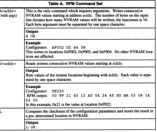
The RFM responds to every command with an echo packet, which is identical to the command packet. If appropriate to the command, the RFM also sends a packet of output data. Table A lists the set of RFM commands used by the configuration program. Listed with each command is the output packet, if one exists. For the sake of brevity, examples do not include echo packets, which always precede output packets. Finally, note that numerical data is always transmitted in hex format.
26
Table A. RFM Command Set
A<addr> This is the only command which requires arguments. Writes consecutive
(with args) NVRAM values starting at address addr. The number of bytes on the input
line dictates how many NVRAM values will be written; the maximum is 16.
Each byte argument must be separated by one space character.
Output
A OK
Example
Configurator: AF002 D2 44 3B
This writes to locations OxF002, OxF003, and OxF004. No other NVRAM
loca-tions are affected.
D<addr> Reads sixteen consecutive NVRAM values starting at addr.
Output
Byte values of the sixteen locations beginning with addr. Each value is
sepa-rated by one space character. Example
Configurator: DF020
RFMoutput: 00 FF 21 45 13 AO 54 34 45 E BA 03 08 1A
D3 00
In this example, 0x21 is the value at location OxF022.
L Computes the checksum of the configuration parameters and stores the result in a pre-determined location in NVRAM.
Output
Table A. RFM Command Set (continued)
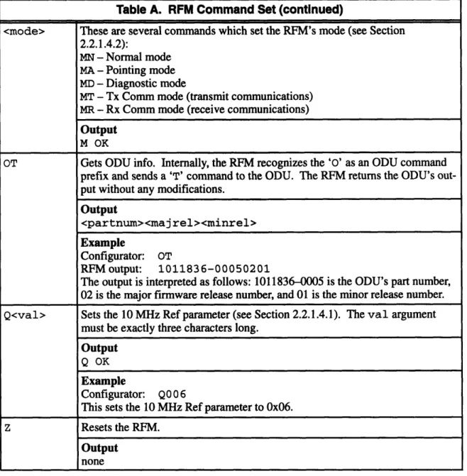
2.2.1.3 RFM Configuration Parameters
The following table shows the name of each configuration parameter and its location in NVRAM. If the parameter maps to a discrete set of NVRAM values, the mapping is shown in the Description field. Appropriate ranges and default values are showed where applicable. Since the configuration program is only responsible for knowing how to map parameters to NVRAM, further knowledge about how each parameter is used internally within the RFM is not necessary. The Offset field shows the offset of each parameter from the 0xF000 base address of configuration parameters in NVRAM.
27
<mode> These are several commands which set the RFM's mode (see Section 2.2.1.4.2):
MN - Normal mode MA - Pointing mode MD - Diagnostic mode
MT - Tx Comm mode (transmit communications) MR - Rx Comm mode (receive communications)
Output
M OK
OT Gets ODU info. Internally, the RFM recognizes the '0' as an ODU command prefix and sends a 'T' command to the ODU. The RFM returns the ODU's out-put without any modifications.
Output
<partnum><majrel><minrel>
Example
Configurator: OT
RFM output: 1011836-00050201
The output is interpreted as follows: 1011836-0005 is the ODU's part number, 02 is the major firmware release number, and 01 is the minor release number. Q<val> Sets the 10 MHz Ref parameter (see Section 2.2.1.4.1). The val argument
must be exactly three characters long.
Output
Q OK
Example
Configurator: Q00 6
This sets the 10 MHz Ref parameter to 0x06. z Resets the RFM.
Output
Table B. RFM Configuration Parameters
Parameter Offset Length Default Description
Name (hex) (bytes)
Mode 00 1 00 Mode of operation. 00 - normal 01 - pointing 02 - diagnostic 03 - tx comm 04 - rx comm
Transponder 01 1 none The frequency window in which the RFM tunes Window the ODU. Window numbering scheme depends on the type of ODU connected to the IDU. Re-gardless of the ODU, window numbers are con-tiguous integer values.
10 MHz Ref 02 2 none Factory set; should not be altered except in maintenance procedures. May be set with the
Q command (see Table A). (Range oooo..OFFF)
RFM CFG 04 1 00 Not used.
RFM U/C Gain 05 2 none Factory set; do not alter. (Range 0000..OFFF)
ODU Gain 07 1 00 Not used. RFT Gain 08 2 0000 Not used. Rx Gain OA 2 0000 Not used. ODU Class OC 1 00 Not used. ODU Latency OD 2 0000 Not used.
Startup ALC OF 1 none Function of four site-specific (non-NVRAM)
parameters and the ODU type.
Keep Alive Time 10 2 0258 Units are seconds. Default 0x0258 = 600
deci-mal, which is 10 minutes. ODU Power 12 2 0000 Range 0000..01FF Offset
ODU Alarm 14 1 00 00 - ignore alarms
Flag 01 - respond to alarms
CU Power Mode 15 1 00 00 - varying 01 - constant ODU Power 16 1 01 00 - constant power Configuration 01 - constant gain Power Control 17 1 02 00 - no power control
Mode 01 - satellite power control
02 - EIRP power control
03 - satellite and EIRP power control
Commissioned 18 2 none Function of three site-specific parameters, sim-Tx Gain ilar to Startup ODU ALC Level.
2.2.1.4 RFM Monitor and Control
There are three monitor and control functions required in RFM configuration. Two of them write to locations in NVRAM, but the important characteristic about these functions is that some aspect of their execution is affected by a time requirement.
2.2.1.4.1 10 MHz Ref
This parameter is part of a feedback loop by which the installer can "tune" the equipment. Setting the 10 MHz Ref parameter affects a particular frequency output on the RFM. The installer reads this output by connecting it to a frequency counter. By "tweaking" the 10 MHz Ref value up or down in small increments, the installer can gradually bring the output on the frequency counter to the right value.
2.2.1.4.2 Mode
The Mode parameter does not require polling like the 10 MHz Ref operation; thus it is less a "moni-tor" function than a "control" function. The Mode commands (see Table A) only set the mode, not
29
Table B. RFM Configuration Parameters (continued)
Parameter Offset Length Default Description Name (hex) (bytes)
Startup ODU Tx 1A 2 0000 Should always be set to 0000. Gain
KCM Present 1C 1 none Whether a certain module is installed in the RFM.
00 - not present 01 - present
PES Present ID 1 01 Whether a PES IDU is connected to the RFM. Almost always set to 01.
00 - not present 01 - present
KCM Receive 1E 2 none Function of Transponder Window and satellite
Channel type.
ODU Minimum 20 2 none Two-byte hex number. Measurable
Power
ODU Maximum 22 2 none Two-byte hex number. Measurable
Power
Ku-band Power 24 1 none One-byte hex number. Detector Range
HPA Present 25 1 none Whether a certain module is installed in the ODU.
00 - not present 01 - present
read it. When a Mode command is sent, the RFM does not accept commands for several seconds
while it sets itself to the new mode.
2.2.1.4.3 Reset RFM
This forces a "reboot" of the RFM. It is often done after new parameters have been written to
NVRAM, so that they may take effect on the system. Similar to the Mode commands, this falls in the "control" category of M&C. The configuration program must wait several seconds after a reset before issuing more commands.
2.2.2 CU interface
This section details the CU's interface with the configuration program.
2.2.2.1 Dandy protocol
Like the RFM, the name of the CU's existing configuration program is also the name of the serial line protocol. The Dandy protocol, like the Term Protocol, is asynchronous and very simple. The
packet format, however, is slightly different: the only required encapsulation is a carriage return at
the end of the data. Figure 11 shows the format of a Dandy protocol packet.
data
CR
Figure 11. Dandy protocol packet format.
2.2.2.2 CU Command Set
Unlike the RFM, the CU does not echo commands. Every command, however, elicits an output pack-et. CU command and output packets have a different format than RFM packets. CU packets never
separate data (bytes, arguments, etc.) by spaces. Figure 12 shows the format of CU command and output packets; elements shown in brackets (<>) may or may not be in the packet, depending on the
type of command. Table C lists the set of CU commands used by the configuration program. For the sake of brevity, the 'S' character that precedes every command and output is not shown; each
com-mand is listed by its ID. Listed with each comcom-mand is the output packet. Since NVRAM is byte
ad-dressed, unless otherwise noted an "NVRAM location" refers to one byte of memory.
There are two states in which the CU operates. In normal operation, the CU is in RUN state, in which
it runs its internal programs and does not respond to any commands except the break. The break com-mands put the CU in BREAK state, in which the CU halts its program run and will respond to any
of the commands shown in Table C.
Figure 12. CU packet formats. 31
IS
id <seg> <off>l<arg> CR
CU command packet
SIidl<1oc>l<1oc>I
.I<loc> CR
CU output packet
where
i d is a one-byte hex number designating the type
of command or output;
seg is a two-byte hex number designating the segment
of the address;
off
is a two-byte hex number designating the offset
of the address;
1 oc is a one-byte hex value of an NVRAM location.
arg is a one-byte hex number of argument data; and
Table C. CU Command Set
ID Description
OD Writes one NVRAM location at address seg:offwith a value of arg.
Output SOD Example
Configurator: SOD7000000310
This sets NVRAM location 0x7000:0x0003 to the value Ox 0.
OA Reads arg number of consecutive NVRAM values, starting with seg:off. The maximum value of arg is Ox10, or sixteen locations. The output contains the values of the arg loca-tions (not separated by any space characters).
Output
S03<1loc><1oc><1oc> ... <loc>
Example
Configurator: SOA7000000003 Output: SO 321A450
This reads three NVRAM locations starting at 0x7000:0x0003. The respective values are
2.2.2.3 CU Configuration Parameters
The following table shows the name of each CU configuration parameter and its location in NVRAM. If the parameter maps to a discrete set of NVRAM values, the mapping is shown in the Description
field. Appropriate ranges and default values are showed where applicable. Since the configuration
program is only responsible for knowing how to map parameters to NVRAM, further knowledge about how each parameter is used internally within the CU is not necessary. The Offset field shows the offset of each parameter from the base address of the configuration parameters in NVRAM, which is contained in address 0x7000:0xOOOl. Note that the NVRAM locations of the parameters are not contiguous.
Table C. CU Command Set (continued)
ID Description
17 Similar to the OD command, except that it reads arg number of two-byte words. The max-imum value of arg is 08, so a maxmax-imum of 16 locations may be read. Output is similar to
OD output. Output SO3<1oc><1oc><1oc>... <loc> Example
Configurator: S177000000002
Output: S 0321A45OBAThis reads two two-byte words from NVRAM starting at 0x7000:0x0003. The respective
values are 0x21, OxA4, 0x50, and OxBA.
OB Issued consecutively, these two commands put the CU in BREAK state. The CU must be 14 in BREAK state before any other commands may be sent. Neither command needs any
arguments. The ellipsis on the end of the second output refers to 19 hex digits following the "S09." These contain no information meaningful to the command.
Output
S03 SO9...
15 This command "unbreaks" the CU and puts it in RUN state. In RUN state, the CU ignores all commands except the break.
Output
S12
OF This command resets the CU. Note that there is no output to this command.
Output
Table D. CU Configuration Parameters
Parameter Offset Length Default Description
Name (hex) (bytes)
Checksum 00 2 none The checksum, although technically not a con-figuration parameter, holds the checksum of all the other parameters. The configuration pro-gram is responsible for keeping the checksum accurate.
Mode after Reset 03 1 00 00 - Operational 01 - Debug/Config OCC Access 04 1 00 00 - IF/RF Link
01 - Serial port (CCU) OCC Data Rate 05 1 * If OCC Access is IF/RF link:
01 - 4800 bps 02 - 9600 bps
03 - 19200 bps *Default for IF/RF link 04 - 16000 bps
05 - 32000 bps 06 - 56000 bps 07 - 64000 bps
If OCC Access is Serial port (CCU): 44 - 300 bps
66 - 1200 bps 88 - 2400 bps 99 - 4800 bps OBB - 9600 bps
0CC - 19200 bps *Default for Serial port (CCU)
OCC IF Freq 06 2 none This parameter is mapped from its hex value to a decimal MHz value by a simple formula. OCC FEC Rate 08 1 01 00 - rate 1
01 - rate 1/2 02 - rate 3/4 OCC Modulation 09 1 00 00 - QPSK Type 01 - BPSK OCC Sweep OB 1 05 05 - 50 kHz Range 06 - 60 kHz ALC OC 1 01 00 - disable 01 - enable
Initial Tx Level OD 1 46 A one-byte hex number. (Range 00..FF)
2.2.2.4 CU Monitor and Control
The user must be able to put the CU in BREAK or RUN mode, and reset it.
2.2.3 IFM interface
This section details the IFM's interface with the configuration program.
2.2.3.1 Term Protocol
As mentioned in Section 2.2.1.1, the IFM uses the Term Protocol for serial port communications. This merits some explanation. As a board in a "standalone" PES IDU, the IFM uses the Term Proto-col. As a target inside the HES IDU, however, it uses the Term Protocol out of necessity: commands
to the IFM are received by the RFM and routed internally to the IFM. Thus the configuration program must use the Term Protocol when sending IFM commands, because it is actually sending them to the RFM. Therefore, IFM commands are encapsulated in the same format as RFM commands (as shown in Figure 10).
2.2.3.2 IFM Command Set
The IFM's command set is almost identical to the RFM's. The "D" and "A" commands (for reading and writing NVRAM locations) are the same, as is the "Z" reset command. The IFM does not support the RFM's M&C commands "L" or "Q", and it does not recognize the "OT" ODU info command. The IFM does have a Mode command, but the format is different from the RFM's Mode command. Table E describes the IFM Mode command.
Since in the HES IDU IFM commands are received by the RFM and routed to the IFM, the overlap
of command sets causes a problem. The RFM must distinguish, for example, a "D" command
in-tended for the RFM from one inin-tended for the IFM. To do this, an additional requirement is imposed
on the IFM command set: all IFM commands must be prepended by a dash (ASCII 45). For example, the reset command in for HES IFM's is "-Z". If the IFM is not part of a HES but is instead inside a standalone PES, the configuration program sends its commands directly to the IFM, and the dash
is not needed.
Table E. IFM Command Set
A, D, Z Identical* to those described in the RFM Command Set (Table A). <mode> These are several commands* which set the IFM's mode (see Section ):
WN - Normal mode WI - Pointing mode WD - Diagnostic mode
*In HES IDU's, all IFM commands must be prepended by a dash (ASCII 45).
2.2.3.3 IFM Configuration Parameters
One difference between IFM NVRAM and other targets is that the IFM configuration parameters are stored in two "parameter pages" in NVRAM, starting at absolute addresses 0x2000 and 0x2100,
spectively. Each page contains values for all the configuration parameters, but only those contained in the "active page" are used. Thus, at a given time exactly one page is designated the active page. (The only exception to this is before the IFM is installed, when neither page is active.) The configura-tion program reads and writes to the active page only. If a major error occurs (which wipes out all the memory in the active page, for example), the inactive page can be made active, and normal opera-tion can resume. Thus the inactive page may be thought of as maintaining a backup copy of the con-figuration parameters.
The following table shows the name of each IFM configuration parameter and its location in NVRAM. If the parameter maps to a discrete set of NVRAM values, the mapping is shown in the Description field. Appropriate ranges and default values are showed where applicable. The Offset field shows the hexadecimal offset of each parameter from the beginning of the parameter page. In two-byte parameters, the least significant byte occupies the lower offset.
Table F. IFM Configuration Parameters
Parameter Offset Length Default Description
Name (hex) (bytes)
Active Page Flag 00 1 none 01 - This parameter page is the active page. 00 - This is the inactive page.
Network ID 01 2 none An arbitrary two-byte number.
Primary Out- 03 3 none Installers are most comfortable with hex repre-route Frequency sentations of the Outroute Frequencies. There-fore, it is not a requirement to display them in units of MHz (as it is for other frequency pa-rameters). There is a particular mapping for-mula which maps the frequencies from hex to Secondary Out- 06 3 none MHz. Also, the byte significance is exception-route Frequency al: the most significant byte occupies the lowest
offset, the least significant byte occupies the "middle" offset, and the "middle" significant byte occupies the highest offset.
Inroute Frequen- 09-47 2 none There are thirty-two Inroute Frequencies, each cies two bytes long. The first Inroute Frequency
begins at offset 09, and the last begins at offset 47 (hex). All Inroute Frequencies are mapped from hex to MHz by the same formula. Usual-ly an IFM will onUsual-ly use five or six of the thirty-two frequencies, but the configuration program must be able to read and write all of them.
Remote Base 4A 1 none Arbitrary hex number, range (0 ..FF). Address
2.2.3.4 IFM Monitor and Control
There are several M&C functions for the IFM, only two of were made a requirements for this thesis: the Reset and Mode commands. The Reset command is identical to the RFM's (see Section 2.2.1.4.3), except that the commaisnd must be preceded by a dash. Similar to the RFM's Mode com-mand (see Section 2.2.1.4.2), the IFM's Mode comcom-mand sets the IFM's mode of operation. Table E details this command.
2.3 Summary
This chapter has described the requirements which must be met by the Configurator. The installers and lab technicians need an easy-to-use interface, and the code maintainer needs the ability to modify the program easily. Each of the three targets - RFM, CU, and IFM - have different require-ments. The protocol, command set, configuration parameters, and M&C requirements of each target were listed.
Table F. IFM Configuration Parameters (continued)
Parameter Offset Length Default Description
Name (hex) (bytes)
Port Card Base 4B-5A 1 none There are sixteen Port Cards in the PES IDU, Addresses each of which has a unique "base address."
Each base address falls in the range (00..7C). Port Card Con- 5B-6A 1 none Arbitrary hex number for each of the sixteen figuration Value Port Cards. May differ from Port Card to Port
Card.
Initial Transmit 6E 1 none Like the RFM's Startup ALC, a hex number Power Level mapped by a multi-argument formula. Initial Timing 6F 2 none Arbitrary hex number.
Offset
Flags 71 1 none The three least significant bits of this byte may be set. All other bits are zero.
Outroute Rate 72 1 none 00 - 128 kbit/s 01 - 512 kbit/s 02 - 1664 kbit/s Inroute Rate 73 1 none 00 - 64 kbit/s
01 - 128 kbit/s
Chapter 3
Implementation
This chapter describes how the Configurator meets the requirements listed in the last chapter. Section 3.1 presents the overall structure of the Configurator. Section 3.2 summarizes the user interface. Section 3.3 goes into greater detail by describing the most important data types. Section 3.4 describes the modules in the core; its discussion is divided between GUI modules and modules called from the menu bar. Finally, Section 3.5 summarizes how the Configurator is tailored to meet the particular requirements of each target, and Section 3.6 summarizes the chapter.
3.1 Configurator structure
Currently, there is a Configurator for each of the three targets. The structure of each Configurator separates the code into two parts: a "core" of target-generic code, which is common to all Configura-tors, and certain target-specific code, which implements the target's specific requirements. The core implements the user interface and any functionality required by all three targets. In practice, all three Configurators are contained on one "field service disk," which the installer carries to the installation
site (see Figure 13).
RFM-ecific
core CU-specific core CU Configurator I-pcoreific I,,, ~RFM Configurator . IFM Configurator
F si .i ,
Field service disk
Figure 13. Configurators and the field service disk.
3.2 User interface
The C-scape graphics library, produced by Liant Corporation, is used to implement the user inter-face. C-scape was chosen because it specializes in interfaces without mouse support. Also, fairly complex interfaces may be implemented with C-scape in a code size of around 150K. The Configu-rator's graphical user interface will hereafter be referred to as the GUI, in order to distinguish it from interfaces between the modules.
Figure 14 shows a typical "screen shot" of the GUI. Most of the screen is taken up by the parameter buffer, where the user may edit the values of the configuration parameters. The parameter buffer shows the title of each parameter and its value. Above the parameter buffer is the menu bar, which contains all the functions accessible to the user. A typical use of the Configurator consists of two basic steps:
1. Editing the parameter values.
2. Choosing the option on the menu bar which writes the values to target NVRAM.
Figure 14. A typical view of the RFM Configurator.
The only other major aspect of the GUI is the mode switch. As stated in Section 2.1.2, the lab techni-cian has different requirements from the installer. While the installer should be protected from mak-ing mistakes such as writmak-ing the wrong NVRAM values, the technician must be provided access to all the NVRAM values. The Configurator meets both sets of requirements by implementing dual-mode operation. Installer dual-mode displays only those configuration parameters which are safe to modify. Technician mode displays the target's entire set of configuration parameters. A special key-stroke is used to toggle modes. Documentation about the mode switch is given to lab technicians only.
GUI paradigm
The Configurator's GUI was designed with a paradigm of simplicity. Here are the principles of the paradigm:
· Consistency. No matter if the cursor is in the parameter buffer, menu bar, or any other window, these keyboard bindings always work the same:
- The arrow keys always control the cursor. In the parameter buffer and any other win-dows, UP and DOWN move the cursor between fields. In windows with a row of
but-tons, LEFT and RIGHT can be used to highlight the desired button.
- ENTER is always used to select the current field. In the parameter buffer, ENTER moves to the next field. On the menu bar, ENTER pulls down a menu, and it chooses the selected menu choice. In windows with buttons, it is the key the user types to "push" the selected button.
· Clarity. No unnecessary details are ever exposed to the installer. This implemented by the following:
- Parameters are given names most easily understood by the installer. - Where applicable, parameter values are displayed in the appropriate units.
- Parameters which the installer does not need to know about are not displayed in in-staller mode.
- Instructions on how to get to technician mode are not displayed, and the keystroke used for the mode switch is difficult to type by accident. The technician mode inter-face displays instructions on how to return to installer mode, in case the mode switch keystroke is typed by accident.
- Messages to the user are written in plain, clear English.
* Exit signs. Instructions on how to exit the current operation are always visible. Windows called from the menu bar either provide a CANCEL button or display instructions about the ESC key. If the user accidentally enters technician mode, the menu bar displays the way to return to installer mode.
In addition to these principles, the Configurator also provides certain features for users who are famil-iar with common PC interfaces. For example, typing the ESC key escapes from every popup screen, and the ALT key can be typed with a letter key to access the menu starting with the letter.
3.3 Data types and the core/target-specific interface
The separation between the core and target-specific code is central to the Configurator. Target-spe-cific code interfaces with the core through the use of tables and functions. Collectively, these
faces draw upon the three most important data structures in the code: the fdefs table, the menu bar tables, and the state structure.
3.3.1 The fdef a table
fdefs is a statically defined table which defines the contents of the parameter buffer. It contains all the vital information about a target's configuration parameters: their names, valid values, how and where they map to NVRAM, and how and where they are displayed in the parameter buffer. Here is its type definition, from the target-generic header file types .h:
typedef struct { /* GUI info */
char *title; /* parameter name */
char *datal; /* non/writeables, or choices */
int row, col; /* position in parameter buffer */
int ftype; /* field type */
char *deflt; /* default value string */
char *range; /* valid range string */
/* map info */
void *field_var; /* field variable pointer */
short standard_map; /* standard map or not */ unsigned nvram_loc; /* nvram offset it maps to */
short numbytes; /* its number of bytes in
nvram */
} Def;
Each Def object contains all the data necessary to define one configuration parameter. To hold the data for all the configuration parameters, fdefs has type Def [. Here is an example initialization
of fdefs:
Def fdefs[] = {
/* both modes */
{ "Commissioned Tx Gain", "##.# dB", 0, 0, UDEC_FIELD, NULL, NULL,
NULL, TRUE, 0x18, 2 },
(
"Startup ALC Level", "## hex",1, 0, HEX_FIELD, NULL, NULL, NULL, TRUE, OxOF, 1 },
{ NULL },
/* technician mode only */
{ "ODU Alarm Flag", "ignore,observe", 2, 0, LIST_FIELD, "ignore", NULL, NULL, TRUE, OxlD, 1 },
{ NULL }, { NULL }
};
In the above example, fde f s is initialized with three configuration parameters. Commissioned Tx Gain has field type UDEC_FIELD, which stands for "unsigned decimal field". "##.# dB" defines the appearance of the parameter's field. The (0, 0) position makes the parameter appear in the upper left corner in the parameter buffer. The s tandard_map, nvram_loc, and numbytes elements define how the parameter maps to target NVRAM. The NULL element after the first two parameters signals the beginning of technician mode parameters. The two consecutive NULL elements signal the end of the table.
3.3.2 Menu bar tables
There are two menu bar tables: one defining the installer mode menu bar, and one for the technician mode menu bar. The initialization of a menu bar table is even simpler than that of fde f s. For
exam-ple:
Menubar my_menubar = {
{ " File ", NULL,
0 },
{ "Open File", open_file, 0 }, { "Save File", save_file, 0 },
{ FRAME_END },
{ " NVRAM ", NULL, 0
},
{ "Write to NVRAM", write_nvram, 0 },
{ FRAME_END }, { FRAME_END }
I};
In this example, the File menu has two options, and the NVRAM menu has one option. Beside each option name is a pointer to the function it calls when selected by the user. Single FRAME_END ele-ments separate individual menus, and two FRAME_END elements signal the end of the table. 3.3.3 Using the tables
Each table described above is defined statically in a target-specific header file. The tables are given
the same names in each header file; thus, it is simple for the core to reference any one of them. For
example, fdefs may be declared by a core module with the following:
extern Def fdefs[];
The advantage of tables is that they are simple to modify. Most of the code maintainer's work, in fact, is limited to the header file which contains fdefs and the menu bar tables.
The problem with tables is that they are limited in capability. Mainly containing scalar data, tables are best suited to "filling in the blanks" in core-defined structures. For example, the parameter buffer is filled in with data from fde f s. Thus, the core defines the extent of a table's usefulness. Whenever a target needs an extension to the core, however, tables are insufficient. This is the case in which a target-specific function is required.
3.3.4 state and target-specific functions
Several locations in the core call target-specific functions to allow the tailoring of a Configurator to the particular target. Target-specific functions must give the programmer as much freedom as pos-sible in extending, or making exceptions to, the core. Therefore, the state object is passed as an argument to target-specific functions. state gives the functions access to virtually everything in the program. Here is its type definition:
typedef struct { /* GUI state */
int which_mode; /* which mode we're in */
sed_type barsed; /* menu bar */
sed_type dentrysed; /* parameter buffer */
/* I/O state */
int ok_to_write_to_target; /* flag OK to write
nvram */
int comport; /* which COM port to
use */
unsigned long base_addr; /* base address of
nvram */
unsigned num_nvram_locs; /* number of nvram
locs */
int *offs; /* array of nvram
void *tspec; /* target-specific
state */
} a_State;
Three of the elements of state -which_mode, barsed, and dentrysed--concern the GUI.
which_mode represents the current mode of the program (installer or technician). barsed and dentrysed are pointers to the menu bar and parameter buffer, respectively. The state members under the "comm state" comment are used in communicating with the target; these are generally used only by functions which read or write the values in the parameter buffer. Finally, tspec is pro-vided to point at any target-specific state data.
Passing state to a target-specific function thus allows the programmer great freedom. barsed and dentrysed allow modifications to any part of the GUI, such as creating new screens with arbi-trary interfaces. The next five elements in the definition allow the function to send arbiarbi-trary com-mands to the target. Finally, tspec can access a data type defined to suit the needs of the target. Despite the advantages gained by passing state as an argument, target-specific functions are still limited. The purpose of target-specific code is to allow the programmer some freedom in tailoring the Configurator to the target. It would be nice if the line between target-specific and target-generic functionality was absolute; after linking in the core modules, obligations to the core would be forgot-ten and target-specific modules could contain arbitrary code. However, that is not the case. The flex-ibility of target-specific code is limited by requirements of the core. (Chapter 4 discusses how most of these problems could have been solved with an object-oriented approach.) Here are the main li-mitations:
· Only the core can define where a specific function may be called. Ideally,
target-specific code would be accessible at arbitrary locations. Nonetheless, the present design has proven sufficient for the Configurators of three separate targets, each with its own modifications to the core.
* Target-specific functions may be required to do certain things. For example, main is required call target-generic functions to initialize state and begin the mode loop. * Function prototypes are core-defined. However, as explained above, state is a
suffi-cient argument to implement a wide range of functionality.
* Every target-specific function called directly from the core must be defined somewhere in the target-specific modules. Even if the function contains only a null instruction, it must exist.