HAL Id: hal-01025210
https://hal.archives-ouvertes.fr/hal-01025210
Submitted on 17 Jul 2014
HAL is a multi-disciplinary open access
archive for the deposit and dissemination of
sci-entific research documents, whether they are
pub-lished or not. The documents may come from
teaching and research institutions in France or
abroad, or from public or private research centers.
L’archive ouverte pluridisciplinaire HAL, est
destinée au dépôt et à la diffusion de documents
scientifiques de niveau recherche, publiés ou non,
émanant des établissements d’enseignement et de
recherche français ou étrangers, des laboratoires
publics ou privés.
Comparison of closed and open thermochemical
processes, for long-term thermal energy storage
applications
Benoit Michel, Pierre Neveu, Nathalie Mazet
To cite this version:
Benoit Michel, Pierre Neveu, Nathalie Mazet. Comparison of closed and open thermochemical
pro-cesses, for long-term thermal energy storage applications. Energy, Elsevier, 2014, 72 (1), pp.702-716.
�10.1016/j.energy.2014.05.097�. �hal-01025210�
Comparison of closed and open thermochemical processes, for long-term thermal energy
storage applications
Benoit MICHELa, Pierre NEVEUa,b, Nathalie MAZETa,*
a
PROMES-CNRS PROcess Materials and Solar Energy Tecnosud, Rambla de la thermodynamique, 66100 Perpignan, France
b
Université de Perpignan Via Domitia, 52 Av. Paul Alduy, 66860 Perpignan, France
Abstract:
This paper focuses on the study of a solid/gas thermochemical reaction between a porous reactive bed and vapor. The objective is to determine the operating mode, either closed or open system, that best suits the requirements of a thermochemical seasonal storage applied to house heating. These two working modes have been compared thanks to two validated 2D models. This study shows that for the chosen set of parameters, the two operating modes lead to close global performances (the average specific power is 0.96 and 1.13 W/kg respectively for open and closed operating mode). Thus, the open thermochemical reactor, which presents technical advantages (easier conception and management, lower cost, …), is a promising way to implement a thermochemical process as long-term heat storage. Moreover, simulations allow identifying the main limitations for each working mode and the ways to reduce them.
Keywords:
Thermochemical process, closed sorption process, open sorption process, long-term thermal storage, second law analysis
* Corresponding author: E-mail: [email protected]
Nomenclature
c molar heat capacity, J∙mol-1∙K-1 standard enthalpy of reaction, J∙mol-1s
cm heat capacity, J.kg -1∙K-1
standard entropy of reaction, J∙mol-1s∙K -1
D thickness of the heat collector, m ε porosity
D’ thickness of the mass diffuser, m μ air viscosity, Pa.s
Dh hydraulic diameter, m ν stoichiometric coefficient, molG/mols
Dec energy density of the reactive bed, J∙.m-3 ρ density, kg.m-3
Decm mass energy density of the salt, J∙kg
-3 Ω
cross section of the salt bed, m2
Der energy density of the reactor, J∙m-3 ρ density, kg∙m-3
h molar enthalpy, J∙mol-1 thermal conductivity, W∙m-1∙K-1
hech thermal losses coefficient, W∙.m -1∙K-1
local entropy production, W∙m-3∙K-1
j molar flow, mol∙.m-2∙s-1
k permeability, m2 Indices
K equilibrium constant 0 dehydrated salt
kcin kinetic constant, s
-1
1 hydrated salt
L length of the reactor, m a dry air
M molar weight, kg∙mol-1
atm atmospheric
m mass, kg c heat collector
n molar density, mol∙m-3 dif diffuser
n unitary vector normal to the boudaries eff effective
N mole quantity of salt, mol eqLG liquid/gas equilibrium
sink or source of gas, mol∙s-1 eqSG solid / gas equilibrium
p
pressure, Pa f at the reaction front Pm specific power, W∙kg
-1
∆p pressure drop across the salt bed, Pa h moist air
sink or source of heat, J∙s-1 i inlet of the porous bed
power, W ini initial
specific power, W∙kg-1 j outlet of the porous bed R
gas constant, J∙mol-1∙K-1 out outdoor total entropy production, W∙K-1 s salt
T temperature, K t total
Tc constraint temperature, K v water vapor
u velocity vector, m∙s-1 X reaction advancement flow rate, m3∙h-1
x x direction
V volume, m3 y y direction
X
reaction advancement z z direction
yv molar water content in the moist air, molv∙molh -1
Z thickness, m
Exponents
Greek symbols 0 reference
free Gibbs energy, J∙mol-1 s
1. Introduction/ objectives
To limit the global warming and reach the Kyoto objectives, it is necessary to reduce the energy consumption and the greenhouse gas emissions. The residential sector is a key issue. For example, in France, this sector represents 43% of the national energy consumption and 25% of greenhouse gas emissions [1]. The use of renewable energies and in particular solar energy for household applications is a relevant mean to reach this target. In order to maximize the use of solar energy for house heating, it is interesting to utilize the solar energy excess in summer using a long-term storage (3-6 months).
Several studies deal with seasonal storage for residential applications [2–4]. Such storage systems must have on one hand the lowest heat losses between summer and winter, and on the other hand, the smaller volume i.e. the highest energy density. Among available processes, a thermochemical storage takes advantage of its high storage density (about 200 to 500 kWh.m-3), and negligible heat losses between the storage and the recovery periods because the energy is stored as a chemical potential and the heat capacity of the components is weak [3]. Therefore, this kind of storage is relevant for seasonal storage for house heating. For comparison purpose, the energy density of latent storage is about 90 kWh.m-3 , and about 54 kWh.m-3 for sensible storage (water for a ΔT of 70 °C and heat losses of 25%) [5].
Such a thermochemical storage process involves a reversible chemical reaction between a solid and a gas. This paper focuses on a hydrate/water pair. The synthesis (or hydration) of the solid is exothermic (heating stage), while its decomposition (or dehydration) requires a heat input (storage stage).
Beside the high storage density criteria, a seasonal storage system has also to fulfill requirements about thermal power production for the heat recovery step. Previous works have defined a target value for this thermal power, for an acceptable range of mass of salt (5 to 10 tons), a typical French climate and an efficient house (Single Family House SFH100 used in IEA works) [6,7]. Thus, the average thermal power required for heating is about: 3.5 kW and, the thermal specific power of the salt ranges between 0.3 to 0.7 W∙kg-1∙ These values are weak compared to those of classical sorption systems (about 10 to 100 time lower), but a long-term storage system is based on a high amount of reactive salt and a low reaction rate. For such large thermal storages, the simplest and efficient reactor configuration has to be designed. Several configurations have been proposed for thermochemical storage reactors [8]. According to Processes, materials and solar energy (PROMES) laboratory knowledge [9–11], a fixed bed configuration is chosen and a modular reactor is designed.
Moreover, for a hydrate/water pair, two operating modes of the thermochemical reactor can be used: closed and open system. In a closed thermochemical system, the salt reacts with pure water vapor at vacuum pressure, while in an open system, the reactive solid bed is crossed by a moist air flow at atmospheric pressure. Many thermochemical systems operate with pure vapor [12–16]. Nevertheless, this kind of working under atmospheric pressure generates strong technological constraints for the thermochemical system design. The open operating mode, at atmospheric pressure, allows to avoid these constraints and it is free of the evaporator/condenser and the water storage reservoir. Thus it could lead to a simpler and cheaper reactor conception [17].
The feasibility of open thermochemical storage system is currently investigated [11,18–23], and seems promising [24]. However, up to date there is no completed seasonal storage based on a thermochemical process [3,17].
Therefore, the objective of this work is to determine the operating mode, either closed or open, that best suits to thermochemical seasonal storage applied to house heating. These two working modes have been compared due to to two 2D models described in this paper. A sensitivity study and a second law analysis allow identifying the main limitations for each working mode and the ways to reduce them. The objective of this paper is to evaluate the performance and limitations of each working mode before setting an experimental bench and performing an experimental study and a thorough validation.
2. Principle of solid/gas sorption processes for seasonal
heat storage
2.1 Solid / gas reaction for seasonal thermochemical storage
A thermochemical system is based on the thermal effect of a monovariant reversible reaction between a solid and a gas:
(1) The equilibrium conditions (peqSG, TeqSG) of the solid/gas reaction follow the Clausius-Clapeyron relation. This
relation is obtained by stating that the free Gibbs energy of this transformation is equal to zero at the thermodynamic equilibrium:
(2)
K is the equilibrium constant for the solid/gas reaction. Assuming that the reactive gas behaves as a perfect gas, K becomes:
(3)
and are respectively the standard enthalpy and entropy of the solid/gas reaction and p0 is the reference pressure (1 bar).
Finally, the thermodynamic equilibrium conditions are determined by only one intensive variable: the equilibrium gas pressure peqSG or the equilibrium temperature of the solid TeqSG:
(4)
This study uses strontium bromide/H2O as a reactive pair. It has been already identified and used in other
<SrBr2∙1H2O> + 5(H2O) ↔ <SrBr2∙6H2O> + Δh 0
r (5)
<SrBr2∙1H2O> and <SrBr2∙6H2O> are respectively the dehydrated (S0) and hydrated (S1) salts and the
reactive gas (G) is water. Their characteristics are detailed in the annex. The reaction advancement is defined as:
(6)
with Ns1,X the number of moles of hydrated salt in the bed at the advancement X, and Ns,t the total number of
moles of salt in the bed. X=0 for the dehydrated solid, and X=1 at the end of the hydration reaction.
The ideal energy storage density of this system is 629 kWh.m-3 (referring to the bulk density of hydrated salt SrBr2∙6H2O[25]). It is 9 times higher than the energy density of liquid water (storage of sensible heat over a
60 K temperature range). Nevertheless, the practical values will be lower because it is necessary to take into account the additional volumes of the gas phase and various parts of the reactor (salt bed porosity, heat exchanger, gas diffuser, dead volumes…).
2.2 Working mode of a thermochemical seasonal storage system
A thermochemical storage system based on a hydration reaction can operate in two different ways in terms of gas supply: with pure vapor (closed system) at vacuum pressure (about 1000 Pa) [9,13], or with moist air (open system) at atmospheric pressure. In this case, the thermodynamic equilibrium conditions (Equation (4)) are related to partial pressure of water in moist air [11].
The thermochemical storage systems studied in this paper include a solid/gas reactor containing a porous fixed bed of reactive solid. Mass diffusers and a heat exchanger (for the closed system case) are necessary to supply/collect the reactive gas and heat to/from the reactive bed (see Figure 2 and Figure 3).
For both operating modes, a seasonal thermochemical storage for house heating works as follows:
- During the heating period (winter): the dehydrated salt S0 (SrBr2∙1H2O) is in contact with the water vapor.
Thus, the exothermic synthesis (hydration) of S1 occurs, releasing heat ( per mol of salt). At the end of
this step, the salt bed is fully hydrated (SrBr2∙6H2O).
- During the storage period (summer): the porous bed of S1 (SrBr2∙6H2O) is heated thanks to the heat
provided by solar collectors. That leads to an endothermic decomposition reaction (dehydration) of salt S1 to
S0.
- Between the storage and heating periods, the reactor is closed, and disconnected from the reactive gas, allowing storing the reaction heat with weak energy losses, over long time. Thus, a thermochemical process is particularly suitable for a seasonal heat storage.
Beside the operating pressure, the closed or open working modes lead to other strong differences. First, the closed operating mode requires an evaporator to generate steam for the hydration phase, and a heat source is necessary (a geothermal source for example). For an open system, the steam is provided by moist air coming from the environment. However, in this case the water partial pressure of ambient air could be too low in winter, and it could have to be humidified before flowing inside the reactor. Secondly, in a closed system, a heat exchanger is necessary to supply/collect the reaction heat. Inversely, in an open thermochemical reactor, the heat transfer fluid and the reactive gas are combined in a single flow. This configuration avoids any internal heat exchanger.
Regarding the system configuration, the two working modes result in different designs and dimensioning. For a closed system, the low operating pressure generates strong technological constraints for the reactor and the evapo/condenser design and manufacturing. Moreover, the evapo/condenser and heat exchanger in the reactive bed lower the apparent energy density, referring to the volume of whole storage system.
On the contrary, the open system allows a simpler manufacturing of the reactor. The evapo/condenser is not necessary, and it doesn’t affect the apparent energy density of the storage system. Nevertheless, this working mode results in a flow of vapor and air through the bed, and the total flow is significantly higher than in the previous case. Thus, mass transfers must be carefully considered.
3. Modeling
Several modeling of solid/gas reactive beds have been developed [26,27], and especially at PROMES laboratory [28–30]. Most of works referring to solid/gas reactions are focused on systems working with pure gas. Some of them are simplified: one dimension model, reaction located on a sharp front… They allow estimating the bed reaction rate for dimensioning purposes. Nevertheless, the analysis and comparison of the two working modes aimed by this paper require an accurate model, taking into account mass and heat transfer within the reactive layer, and the differences due to pure gas or moist air flows.
Thus, a general and original two-dimension model has been developed first. It takes into account heat and mass transfer within the reactive bed and with the moist air flow. Thanks to additional assumptions, this model was modified to represent the same porous bed reacting with pure vapor.
Both models are dynamic and couple heat balances, mass balances and a kinetic equation. The following assumptions are used:
(a) : The reactive bed is pseudo-homogeneous: the reactive solid and gas phases (vapor or moist air) are assumed at the same temperature. This assumption is often used [26], and it can be justified by the high solid/gas heat transfer rate usually observed in such porous media, with small grain sizes (<0.5 mm).
(b) : mass transfer in the porous bed follows the Darcy law. The vapor velocity is usually low in such porous bed of thermochemical systems, thus the inertial effects can be neglected [11,31,32]
(c) : heat transfer in the porous media are conductive, according to Fourier law, and convective (d) : the kinetics of the reversible solid gas reaction involved in such a process depends on the reaction advancement and on the equilibrium drop [30].
Depending on each working mode, additional assumptions are described in the following sections.
Moreover, the permeability, conductivity and kinetic parameters have been measured for high density reactive porous beds, thanks to previous experimental studies [11,32,33]. These measurements give a relevant range of transfer and kinetic parameters for the analysis of the working mode of thermal energy storage carried on in this paper.
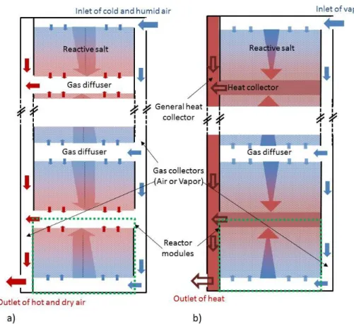
According to PROMES laboratory knowledge [9–11], we have designed a modular concept of thermochemical reactor by stacking several rectangular modules. Each module consists of:
- a reactive layer inserted between two gas diffusers, one connected to the air input and the other to the air output, for the open reactor (see Figure 1a),
- a reactive bed inserted between a plate heat exchanger and a gas diffuser on the other side for the closed reactor (see Figure 1b).
All the modules are connected in parallel to the heat and mass input and output. Therefore, the study can be restricted to only one rectangular module, (see Figure 2 and Figure 3). In order to define a relevant shape factor (ratio of height to length of the bed section) for this comparison, a previous simplified model was used (stationary, one-dimension, pure gas) [32,34]. This model is based on the well-known constructal method. It aims to calculate the shape factor optimizing the ’volume to point’ transfers i.e. the heat and mass transfers between the reactive layer and a point at its boundary where the heat and mass collectors or diffusers are located. The optimal shape of the reactor is obtained by minimizing the total entropy generation in the reactor. This method has been proven able to provide relevant shape factors, close to optimal values resulting from more complex 2D dynamic studies [28]. The dimensions of the reactor obtained with this method are presented in §4.1.
The following sections detail the general modeling developed for the open system, and its simplification to model closed working mode. The set of equations is solved by a finite element method using a commercial tool (COMSOL®).
Figure 1: Schematic representation of a global thermochemical reactor:
a) open system (operating with moist air), b) closed system (operating with pure vapor).
3.1 Open thermochemical reactor
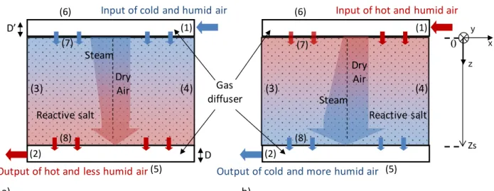
For an open thermochemical reactor, gas diffusers supply/collect the moist air flow at the inlet/outlet of the reactor. Moist air enters the reactor from the inlet diffuser side, and then it flows through the reactive layer from the top to the bottom side (Figure 2).
Depending on the thermodynamic operating conditions, it causes either an exothermal hydration, or an endothermal dehydration of the salt. During the hydration step, a part of the reaction heat is transferred across the bed by conduction, but most of it is transferred to the moist air flow. Thus, the moist air flowing out by the bottom side of the bed is hotter and dryer than the inlet moist air flow (Figure 2a). On the other hand, during the dehydration step, the moist air flow provides heat required by the reaction in the bed. Thus, the outlet moist air flow is colder and wetter than the inlet one (Figure 2b).
Figure 2: Schematic representation of an open thermochemical reactor (operating with moist air) a) Hydration step, b) Dehydration step. (Numbers refer to boundary conditions described below).
The dynamic modeling of this open system requires an additional assumption:
(e) : Moist air is a mixture of two ideal gases: dry air and water vapor. This assumption is usually used for this range of pressure (atmospheric pressure), temperature (<100°C) and partial pressure of water vapor (<10 kPa) [11,35].
The set of equations required by this modeling is described below. 3.1.1) Molar balance
The molar conservation is applied to the moist air flow:
(7)
u, the velocity of moist air is evaluated through Darcy law:
(8)
According to assumption (e), equation (7) can be composed of two molar balances, one for dry air and the other for vapor:
Dry air
(9)
Vapor (10)
where:
, is the gas source or sink due to the reaction (kg.m-3.s-1). yv, is the molar water content in the
moist air flow, which depends on the water partial pressure according to :
(11) By developing the molar balance for vapor, molar balance of the water contained in the moist air flow is obtained:
(12)
Thus, the molar balance in the reactive bed is given by equation (7) and equation (12). Indeed, it is easier to work with variables and balances involving the total flow of moist air on one hand (Equation (7)) and the molar concentration of vapor on the other hand (Equation 12).
For the reactive bed, this system writes:
(3) (4)
Input of cold and humid air
Reactive salt 0 Zs Dry Air Steam a) z x
Output of hot and less humid air(5)
(6) (8) (7) (1) (2) (3) (4)
Input of hot and humid air
Reactive salt
b)
Output of cold and more humid air (5)
(6) (8) (7) (1) (2) Gas diffuser Dry Air Steam D’ D y
(13)
(14)
with εs: porosity of the reactive bed,
Equations (13-14) also stand for the gas diffusers, by cancelling the source term:
(15)
(16)
with εdif: porosity of the mass diffusers.
3.1.2) Energy balance
According to assumptions (a) and (c), the energy balance of the solid porous layer writes as:
(17)
where: (18)
The three right side terms refer respectively to the conductive heat flow across the porous solid layer, the enthalpy variation of the flow of moist air, and the heat source or sink due to the reaction (W∙m-3).
In the mass diffusers, heat transfers are not modeled. Flow is assumed to be isothermal. 3.1.3) Kinetics
For this kind of solid/gas reactions, the kinetic reaction depends on the difference between the operating conditions pv, T and the thermodynamic equilibrium defined by Clausius – Clapeyron relation peqSG(T)
(Equation (4)). For this open working mode, pv is the partial pressure of water. As the solid is consumed
during the reaction, the kinetics also depends on the reaction advancement. Previous study [36] has shown that it can be expressed by a 1st order kinetic law, respectively Equation (19) for hydration reaction and Equation (20) for dehydration :
(19)
(20)
3.2 Closed thermochemical process
The transformation of closed thermochemical reactors based on similar solid/gas reaction has already been modeled by previous authors [27].
For the comparison of the two working modes aimed here, we decided to derive the closed system model from the previous one involving moist air. Beside previous assumptions (a) to (d), additional assumptions, (f) to (h), are required to simplify the open system modeling accordingly. They are described in the following section.
Moreover, unlike the open reactor, a closed reactor needs a heat exchanger to collect or supply the reaction heat, in addition to a gas diffuser. Thus, these two elements have to be modeled and coupled with the reactive bed (Figure 3).
3.2.1) Assumptions
(f) no inert gas enters the reactor
(g) due to the low vapor flow through the porous reactive bed, heat transfers are mainly conductive, and are represented by an effective conductivity. Thus convective heat transfers due to the flow of pure vapor in the porous layer is neglected
(h) the sensible heat of the vapor is neglected, compared to the solid reactant sensible heat.
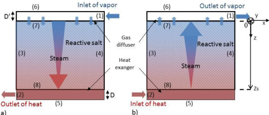
Figure 3 schematizes the closed thermochemical reactor. It includes three elements of the same length L: the gas diffuser, the reactive layer and the heat conductive fin.
For synthesis reaction, vapor enters from the mass diffuser located at the top of the salt layer, then it flows through the reactive bed leading to an exothermal reaction. The resulting heat is transferred by conduction through the porous layer to the exchanger at the bottom of the layer (Figure 3a), then to users.
During the decomposition (heat storage step), this heat exchanger is connected to the external heat source and transfers heat to the porous reactant. It results in an endothermal decomposition that produces vapor which is diffused trough the layer and which is collected thanks to the mass collector (Figure 3b).
Figure 3: Schematic representation of a closed thermochemical reactor (operating with pure vapor). a) Hydration step, b) Dehydration step. (Numbers refer to boundary conditions described below). The thicknesses of the conductive fin, reactive layer and mass diffuser are respectively D, Zs and D’.
3.2.2) Mass balance
Regarding the total gas flow passing through the porous layer, the mass balances are similar for both operating modes. Thus, the vapor balance (Equation (21)) for a closed system is the same as the moist air balance in the previous case (Equation (7)) with the corresponding variable, nv.
In addition, equation (22) represents the vapor mass balance in the diffuser at the top of the layer.
(21) (22) The velocity u is given by Darcy law (Equation (8)).
3.2.3) Energy balance
According to assumptions (g) and (h), the energy balance of the reactive layer can be simplified to equation (23). The energy balance of the heat collector has to be added (Equation (24)).
(23)
3.2.4) Kinetics
The kinetic equations are unchanged compared to previous cases (Equation (19) and (20)). They involve the thermodynamic equilibrium pressure peqSG(T) (Equation (4)) where pv is the total vapor pressure in this
closed system case.
3.3 Boundary and initial conditions
We consider that the gas diffusers are composed of an air blade. It is modeled as an equivalent porous medium, whose porosity is 1 and permeability is calculated from Darcy-Weisbach equation and Hagen-Poiseuille correlation:
(25)
with: L the length of the gas diffuser, and Dh the hydraulic diameter.
Darcy’s permeability then writes:
(26)
The resulting permeability of this air diffuser is high (about 10-6 m2). Thus, for the open system case at atmospheric pressure, mass transfer limitation due to this mass diffuser is negligible and this diffuser will not be modeled. Nevertheless, at vacuum pressure, this gas diffuser can affect the overall mass diffusion and it has to be taken into account in the closed reactor modeling.
Additional boundaries and initial conditions are described below for each model:
3.3.1) Open thermochemical reactor model (referring to boundary numbers stated on Figure 2)
face (7): air feeding
The flow rate (ui), molar water content (yvi) of the inlet moist air are imposed. As inlet temperature Ti and
local reactive medium temperature T can be different, some heat exchange has to be taken into account between the inlet air and the upper surface of the reactive medium to fulfill the pseudo-homogeneous bed assumption (a) (i.e. the inlet air instantaneously reaches the local bed temperature when entering in this domain). This boundary condition expresses this effect:
(27)
face (8): air outlet
ptj = pti + Δp = patm. (28)
, (29)
(30)
walls (3 and 4):
, (31)
Heat losses are neglected in hydration (hech=0), because the temperature difference between the reactor and
the environment is low, but they are taken into account in dehydration phase:
(32)
3.3.2) Closed thermochemical reactor model (referring to Figure 3)
Eight boundary conditions have to be stated on sides and walls of the diffuser, collector and reactive layer:
mass diffuser (1) : the vapor pressure (pvi )is imposed.
heat exchanger (2): The temperature (Tj) is imposed.
side boundaries (3 and 4): similar to open system case: Equation (31) and (32),
symmetry conditions (5 and 6): Equation (29) and Equation (33):
reactive layer: on (7): Equation (29), and on (8): Equation (33)
3.3.3) Initial conditions
At t=0, the temperature (Tini) and advancement (Xini) of the reactive bed are known, and the reactive salt is at
its thermodynamic equilibrium:
Thermodynamic and physical data related to the reactive solid and vapor are summarized in annex.
These sets of equations are solved in the bed section by a finite element method. A 2D rectangular and irregular meshing is used. Meshes are thinner near the top and bottom faces than in the middle of the reactive layer (ratio: 1/10).
3.4 Validation of the model
As similar models for closed systems have already been validated in previous works [29,36,37], this validation focuses on open systems due to available experimental results of a prototype of thermochemical energy storage [32]. This experimental set up is beyond the scope of this paper, and it is only briefly described here. Further papers will focus on the experimental work. This prototype contains 300 kg of SrBr2∙1H2O, reacting with water to form SrBr2∙6H2O. The reactor is designed in a modular way, by
assembling eight layers, 7.5 cm thick. The energy density is 388 kWh.m-3 (referring to the volume of the reactive bed). On one side of each layer, an inlet gas diffuser supplies a flow of moist air that passes through the layer and is collected on the opposite side by an outlet air collector. Several hydration/dehydration cycles have been carried out, under moist air flow at constant temperature, humidity and mass flow rate (Table 1). Reaction times are rather long, typically about 15 days for a cycle, as the system is designed for long-term storage. The modeling has been validated using a typical set of successive hydrations operating according to Table 1 conditions. Ti (°C) pvi (Pa) Flow rate (m3/h) kcin (s -1 ) Hydration 1 25 997.5 289.6 8∙10-6 Hydration 2 25 981 290 5.5∙10-6 Hydration 3 25 944.7 280.2 3∙10-6 Hydration 7 24.8 968.2 271.8 3.5∙10-6
Table 1: Experimental operating conditions for several hydration/dehydration phases of an open system. kcin, the kinetic parameter (Equations (19) and (20)), is identified using the 2D model.
Mass transfer parameters have been measured in a specific set-up [11]: the permeability evolves between k0=5.9∙10
-12
and k1=211.6∙10 -12
m2 during the reaction, because hydration and dehydration lead to a large change in the molar volume of the solid and on the porosity of the reactive grains [11]. The bed conductivity is calculated thanks to correlations depending on the density of the reactive layer [33] (Archie law, Equation (35)).
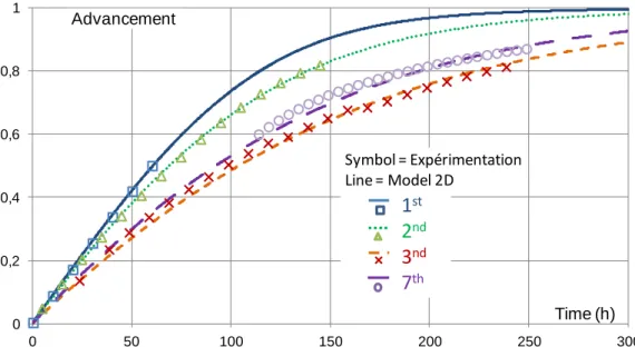
Figure 4 presents simulations that fit adequately to experimental results for several successive hydrations. These experimental kinetics decrease during the first cycles, then stabilize. This effect is well-known for such solid/gas reactions. Breakages of grains and re-organizations of the porous network in the salt bed during the first cycles could explain this behavior. These breakages are due to the strong mechanical stress that results from the change in grain volume during hydration. Consequently, different values of the kinetic parameter have to be identified for these successive cycles (table 1, last column). Thanks to these values, the difference between experimental and simulated reaction rates is rather low: at X=0.5, it is 1%, 2% and 6%, respectively for hydrations 1 to 3.
Figure 4: Reaction advancement versus time for several successive hydrations. Experimental and simulated results for hydrations 1, 2, 3 and 7.
These results demonstrate that the 2D model predicts in a satisfactory way the reaction rates for open system. Thus, this tool is relevant for the purpose of this paper that aims at comparing a different operating mode, using moist air, to the classical one, with pure vapor.
4. Comparison of local behaviors
Thanks to the two previous validated models, this part aims at analyzing the local behavior of a thermochemical system and determining the main limitation, according to the two working modes.
4.1 Framework of the comparison
A single geometry of the reactive layer is used for both cases. The rectangular cross section of the reactor is defined by its thickness Zs. Decreasing the reactive bed thickness allows to increase the thermal specific power. Nevertheless, because the thickness of the heat and mass diffusers can’t be reduce beyond few millimeters, decreasing the bed thickness leads to a decrease of the reactor energy density (Der), which is an important constraint of a seasonal storage. Therefore, compromises between the reactive bed thickness and the Der have to be made. Thus, a thickness Zs=5 cm, which can easily be implemented in a prototype or an industrial system, has been chosen for this comparison.
For the closed system, an additional study based on a constructal approach has been carried out to define the mass diffuser and heat exchanger thicknesses [28,32,34].This approach leads to optimal shape factors for the reactive layer and diffusers that optimize the overall heat and mass transfer in the whole system. A geometry close to this optimum was used. The reactor length is L=44 cm and the thicknesses of the mass diffuser and heat collector are D=D’=0.3 cm. For the open system, a similar optimal approach cannot be developed because the system involves only the reactive layer. Indeed, the heat diffuser is not required as heat is transferred through the moist air flow, and the diffuser is not modeled as discussed in § 3.3. Consequently, the geometry defined for the closed system has been used for both cases as this choice allows a better comparison.
The energy and transfer parameters are summarized in Table 2. The energy density of the reactive layer is fixed at a high value required by the long-term storage purpose of the system: Dec = 450 kWh.m-3. Previous experimental works have proven the feasibility of the reaction in such a high density reactive bed [11]. Adding heat and mass diffusers for the closed system, and mass diffusers for the open system, is mandatory
0 0,2 0,4 0,6 0,8 1 0 50 100 150 200 250 300 Advancement Time (h)
1
st2
nd3
nd7
th Symbol = Expérimentation Line = Model 2Dand it lowers the energy density of the system: for the geometry under study, the final energy density related to the whole reactor (Der) is 11% lower than the reactive layer one (Dec).
The variations of heat and mass transfer parameters due to the reaction have been taken into account. The equivalent permeability and the effective conductivity are calculated according to Equation (34) and Equation (35), based on respectively the assumption of a sharp front moving axially through the bed [11] and the Archie law.
(34)
(35) with λs=1 W/m/K the conductivity of the salt grains, and (k0, ε0) and (k1, ε1) the bed permeability and porosity
at both ends of the reaction (see Table 2 and annex).
Finally, we consider that kinetics doesn’t limit the thermochemical reaction. The kinetic parameter has been fixed at 10-4 s-1, as it has been proven that kinetics is not limiting as far as this parameter is higher than 10-5 s-1 [32].
Closed system Open system Energy density of the reactive salt, Dec, kWh∙m-3 450
Energy density of the reactor, Der, kWh∙m-3
400 Reactive bed thickness Zs / length L (m) Zs=5 cm, L=44 cm Permeability of the bed: m2 k0 = 1∙10
-10
to k1 = 5∙10 -12
Porosity of the bed ε0 = 0.63 to ε1 = 0.28
Thermal conductivity of bed (λs=1 W∙m -1∙K-1
),
W∙m-1∙K-1 λeff0 = 0.22 to λeff1 = 0.61 Thermal conductivity of the collector W∙m-1∙K-1 λc = 330 -
Diffuser permeability, m2 kdif = 4.5∙10 -6
Kinetics constant, s-1 kcin = 0.0001
Vapor pressure at the reactor inlet: pvi , Pa 1200
Constraint temperature (exchanger outlet) Tj, °C 35 -
Moist air inlet temperature, Ti , °C - 20
Pressure drop through the reactive layer, Δp, Pa - 500
Table 2: Reference values for an open and closed system comparison: physical parameters and operating conditions for hydration.
The two working modes are compared during a hydration step, i.e. the winter heating step which defines the operating temperature and pressure used as boundary conditions (Table 2). For the closed system, vapor is supposed to be generated by an evaporator using a free geothermal heat source at about 10°C, which defines the inlet vapor pressure pvi for the reactor. On the other hand, the outlet temperature of the heat
exchanger Tj is fixed by the heating requirement. For the open system, the same value pvi is used as water
partial pressure. Moreover, the pressure drop through the layer is fixed at a value consistent with a prototype or industrial implementation (Δp=500 Pa).
The aim of the following sections is first to identify the limitations of the thermochemical reaction for the closed and open systems, and second to compare performances of these two kinds of storage systems. This study is carried on around the reference case in hydration summarized in Table 2.
4.2 Moving of the reactive front
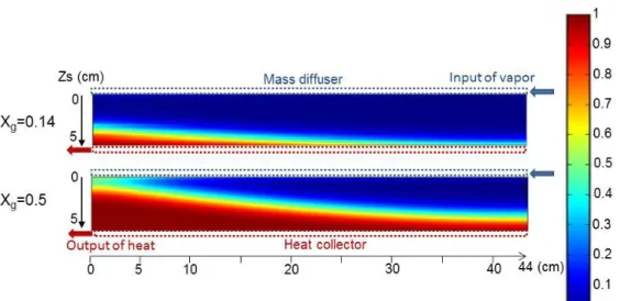
Figure 5 and Figure 6 present local reaction advancement fields respectively for closed and open system cases. These fields are plotted at two global advancements in the reactive bed: at the beginning of the reaction (X= 0.14) and during the middle of the reaction.
4.2.1 Closed system
First, Figure 5 highlights a sharp reaction front separating a fully reacted part (X=1, red or light) and an unreacted part (X=0, blue or dark) of the bed.
In addition, these figures show that the reaction starts at the bottom of the layer i.e. at the heat exchanger side. At the beginning of the reaction (upper map, X=0.14), a fully reacted layer (red layer, X=1) appears near the heat exchanger, and it extends towards the gas diffuser side (top of the layer) while the reaction progresses (lower map, X=0.5). Therefore, the main sharp reaction front moves from the heat exchanger towards the gas diffuser during the reaction. This proves that the heat transfer is the main phenomena limiting the hydration reaction, carried out under pure vapor. Although the operating vapor pressure is low, the effective conductivity of the porous media is also very low. As a result, the heat transfer is the main limitation of the solid/gas reaction. In order to overcome this well-known limitation, it is possible to increase the effective bed conductivity by adding a conductive and inert binder (as expanded natural graphite) in the reactive porous salt [12,31].
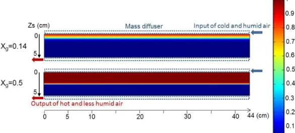
4.2.2 Open system
This working mode leads also to a sharp reaction front separating the reacted and unreacted layers. But in this case, the reaction begins initially from the upper part of the reactor where moist air enters the bed. Then, the reaction front moves in the air flow direction, towards the bottom side of the bed. However, in this case, the flow of heat and mass are co-current and not counter current as in the previous closed system case.
As heat and mass inlets are not located at distinct sides of the bed, the analysis of the moving of the reaction front does not allow any conclusion about the transfer that mainly limits the reaction.
Figure 5: Maps of local advancement of the closed reactor, for two global advancements: a) Xg=0.14 (t=22.2 h) and b) Xg=0.5 (t=100 h).
Figure 6: Maps of local advancement of the open reactor, for two global advancements: a) Xg=0.14 (t=7.8 h) and b) Xg=0.5 (t=69.7 h).
However, the limiting phenomena can be determined in a stronger way by the analysis of the entropy production in the reactive salt, described in the following section.
4.3 Second law analysis
Several irreversible phenomena occur in a thermochemical reactor: heat conduction, mass transfer and chemical reaction. Their impact can be assessed through their respective entropy productions [34]. In this section we focus on the entropy production within the layer of reactive salt.
4.3.1 Closed system
The total entropy in the reactive salt writes:
(36)
As deeply detailed in [28,34], using the first and second laws of thermodynamics, Gibbs equation [38] and neglecting the mass diffusion in the open system case, the local entropy production writes:
(37)
These terms are numerically calculated thanks to available tools of the 2D software used for simulations, and are presented in this paper per meter of reactor depth.
The salt entropy production can then be split in three terms related to the three irreversible phenomena occurring in the reactive layer: heat transfer , mass transfer and kinetics . Thus, the total entropy productions, over the layer are expressed in equations (38) to (40), and plotted in Figure 7:
(38)
(39)
(40)
Figure 7 shows that, the entropy production in the reactive layer results mainly from the heat transfer. Over the total reaction, the average entropy production due to the heat transfer is about 7.4 times higher than the
mass transfer one, and about 3 times higher than the kinetic entropy production. This analysis confirms that the heat transfer is definitively the main limitation of reaction in such a reactive bed of a closed system.
Figure 7: Entropy productions in the reactive salt bed of a closed reactor. Productions are related to: kinetics, mass and heat transfer, and total production. Parameters and bed dimensions are in table 2. Results are given per meter of reactor depth (W∙K-1
/m).
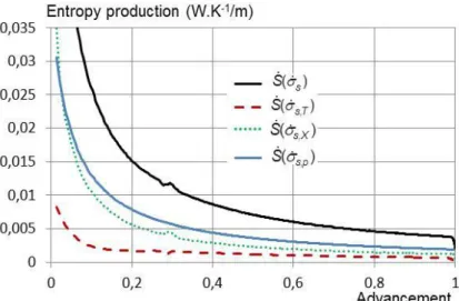
4.3.2 Open system
The same equations (38) to (40) can be used to calculate the three types of entropy productions in the reactive bed of an open system. These three terms are plotted in Figure 8. Due to the pressure drop imposed across the reactive bed, the entropy production is higher in magnitude than in the vapor pure reactor. However, it is now mainly due to the mass transfer, all over the reaction (except at the very beginning of the reaction).
Thus, the mass transfer is the main phenomenon limiting the hydration of a salt bed of an open system. It should be notice that, as in previous cases, the entropy production due to kinetics is not negligible. This feature is deeper analyzed in the following sensitivity study (§ 4.4 and Figure 10).
Figure 8: Entropy productions related to kinetics, mass and heat transfer, and total entropy production occurring in a reactive layer of an open system. Results are given per meter of reactor depth (W∙K-1/m).
As a result, the salt layer reacts in a strongly different way for an open or a closed system. The most limiting phenomena within the reactive layer are the heat transfer in a closed system and the mass transfer in an open system.
Nevertheless, these conclusions are drawn for the range of physical parameters and working conditions listed in Table 2. The following section investigates the threshold values of transfer parameters that could change these features.
4.4 Sensitivity to transfers parameters
For each operating mode, this study focuses on the relevant transfer parameters corresponding to the main limitations: thermal conductivity for closed systems, and permeability for open systems. The part of each phenomenon (kinetics, heat and mass transfer) in the total entropy production over the reaction is analyzed. It is calculated by integrating equations (38) to (40) over the reaction time.
4.4.1 Thermal conductivity of the reactive layer (closed system)
Simulations have been performed for conductivity of the salt grains ranging from the reference value
λs=1 (Table 2) to 0.5, 2, 5, 50 and 100 W/m/K. This results in an increase of the effective conductivity of the
reactive layer according to Equation (35).
The resulting advancements versus time are presented in Figure 9a. The reaction rate increases with the salt grain conductivity. Nevertheless, from λs=5 W∙m
-1∙K-1
the reaction rate increases slower with the conductivity. Thus, the heat transfer is no more limiting over this conductivity value, when other parameters are kept constant at their reference values. Moreover, the part of each phenomenon in the total entropy production (over the reaction) plotted on Figure 9b, confirms that, from λs = 5 W∙m-1∙K-1, the heat transfer is
no longer the main part of the total entropy production.
Figure 9: Simulations of hydration in a closed system
a) Advancement vs time for various thermal conductivities of the salt grain (and reactive bed, see eq.35). b) Part of each phenomena (kinetics, heat and mass transfer) in the total entropy production (over the reaction), λs=1, 2 and 5 W∙m-1∙K-1
.
For other parameters: reference values listed in Table 2.
Moreover, Figure 9a shows that a moderate increase of the bed conductivity leads to a significant decrease of the reaction time. For example, time to reach X=0.9 is 14% lower when λs changes from 1 (reference
value) to 2 W∙m-1∙K-1 (ie. λ
eff0=0.45 and λeff1=1.22 W/m/K). Over that, increasing λs from 1 to 50 W∙m-1∙K-1 only
results in 45% less in the reaction time at X=0.9.
Thus, it could be interesting to only slightly increase the conductivity of the porous reactive bed, for example by adding a conductive graphite binder as developed by several authors [29,33]. This will enhance the reaction rate in the reactive bed and as a result increase the thermal power outlet of the storage system. 4.4.2 Mass transfer parameter (open system)
A deeper investigation has been carried out as this parameter can strongly evolve during the reaction due to the change in bed structure and porosity. First, this sensitivity study investigates permeabilities from 0.5 to 20 times the reference values. Then, it focuses on the permeability change with the reaction advancement by analyzing separately the sensitivity to k0 and k1. These sets of values are listed in Table 3.
b) 0 0,1 0,2 0,3 0,4 0,5 0,6 0,7 0,8 0,9 1 0 50 100 150 200 250 300 350 400 1 (ref) 0,5 2 5 50 100 Time (h) λs(W/m/K) Advancement a) 0% 10% 20% 30% 40% 50% 60% 70% 80% 90% 100% , ( s T) S , ( s p) S , ( s X) S 1 (ref) 2 5 λs(W/m/K)
Simulation k0 (10 12 *m2) k1 (10 12 *m2) k (reference case) 100 5 2k 200 10 10k 1000 50 20k 2000 100 k/2 50 2.5 10k0 1000 5 10k1 100 50
Table 3: Equivalent permeabilities of the hydrated (k1) and dehydrated (k0) reactive salt bed used in simulations of open system model (cf. Figure 10).
Figure 10a shows the advancement plots for these simulations. The permeability has a strong influence on the reaction rate, for values up to 10 times the reference values. Moreover, the reaction time reduction is directly correlated to the increase in permeability. For example, the bed reacts twice faster when the permeability is doubled (curve 2k, Figure 10a). That proves that the mass transfer is the only one limiting phenomenon. Indeed, as the pressure drop is kept constant in the bed (see Table 2 and Equation (34)), the moist air flow is directly proportional to the permeability, according to Darcy law (Equation (8), and when a higher vapor flow reacts with the salt, the reaction rate increases to the same extent. This is true as long as kinetics is not limiting. For permeabilities over 10 times the reference values, the permeability and reaction rate enhancements are no more correlated. Compared to the reference simulation, the reaction rate at X=0.9 is divided by 10, 17 and 25 respectively for simulations with 10k, 20k and 50k. Therefore, the main limitation changes, and this is confirmed by the second law analysis Figure 10b. For simulations with10k and 20k, the entropy productions related to kinetics and mass transfers are almost equivalent, and the mass transfer is no more the main limitation. Thus, increasing the equivalent bed permeability up to 10k, by technical means such as a porous binder is an efficient way to improve the thermal output power of the storage system. Additional simulations show logically that the mass transfer limitation has a stronger effect at the end of the reaction. Figure 10a shows clearly that, increasing 10 times the permeability k1 (end of reaction) is much
more efficient than 10 times k0. Thus, the permeability at the end of the reaction is the key dimensioning
parameter for this range of reactive beds for storage processes.
Figure 10 : Open system case.
a) Advancement vs. time for various permeabilities listed in Table 3. k is the reference value (see Table 2). b) Part of each phenomena (kinetics, heat and mass transfer) in the total entropy production (over the reaction). Permeabilities: k, 10k and 20k. Reference values for other parameters.
4.4.3 Kinetic parameter
In both previous cases, the main limitation deals with a transfer phenomenon, and kinetics is never limiting. This part aims at evaluating the threshold of kinetic parameters leading to a kinetic limitation, for both working modes.
First, for the closed system, simulations have been performed in a large range of kcin values from 10 -6
up to 10-3 s-1 (Figure 11a). The second law analysis is focused on kcin=10
-4
s-1 (reference value, Figure 7b), 5∙10-5 s-1 and 10-5 s-1 (Figure 11b) and it displays a strong increase of the entropy production due to kinetics
0 0,1 0,2 0,3 0,4 0,5 0,6 0,7 0,8 0,9 1 0 50 100 150 200 250 Advancement Time (h) k 10k0 10k1 k/2 2k 10k 20k 50k Permeability a) b) 0% 10% 20% 30% 40% 50% 60% 70% 80% 90% 100% 1k (ref) 10k 20k , ( s T) S , ( s p) S , ( s X) S
between these three cases. Both figures prove that kcin= 5∙10 -5
s-1 is a threshold value: above it, kcin doesn’t
influence the reaction rate; and below it, kinetics becomes a limiting phenomenon that slows down the reaction.
Figure 11: Closed system case.
a) Incidence of kcin value on the reaction rate.
b) Part of each phenomena (kinetics, heat and mass transfer) in the total entropy production (over the reaction), kcin=10-4, 5∙10-5 and 10-5 s-1. Reference values for other parameters.
For the open system case, a similar study has been carried out. It leads to similar conclusions and displays a threshold value about kcin =5∙10
-5
s-1. Below this value, kinetics have an impact on the reaction rate.
Furthermore, this evolution of the main limitation, from a transfer limitation to a kinetic one, results in very different local reaction rates. Figure 12 presents maps of local reaction advancements in the cross section of the reactive bed, for kinetic parameters in the same range as in Figure 11 (kcin = 10
-5
to 10-3 s-1). When the heat transfer is limiting (top map), the salt reacts as soon as heat is provided. Thus the reaction occurs on a sharp front. When kinetic limitation increases, this front becomes smoother and disappears for kcin = 10
-5
s-1 (lower map). In this latter case, transfers are not limiting and the thermodynamic conditions are suitable for reaction throughout the reactive bed. This behavior is similar in closed and open system cases.
Figure 12: Maps of local reaction advancements at the same global advancement: X=0.5, and for various kinetics parameters (10-3 to 10-5 s-1). 0 0,1 0,2 0,3 0,4 0,5 0,6 0,7 0,8 0,9 1 0 100 200 300 400 500 600 10-4(ref) 10-3 5 10-5 10-5 10-6 Advancement Time (h) kcin(s-1) a) b) 0% 10% 20% 30% 40% 50% 60% 70% 80% 90% 100% , ( s T) S , ( s p) S , ( s X) S 10-4(ref) 5 10-5 10-5 kcin (s-1)
Mass diffuser Input of cold and humid air
0 5 0 L (cm) 44 kcin=10-5s-1 kcin=10-4s-1 kcin=10-3s-1 Zs (cm) 0 0.1 0.2 0.3 0.4 0.5 0.6 0.7 0.8 0.9 1 Advancement
5. Global performances of the reactive bed
5.1 Comparison of the global performance of each operating modes
The previous sections analyzed the local behavior for the two working modes, the closed and open system, and highlighted the limiting phenomena for the hydration reaction.
Besides, global performances of a thermochemical storage reactor have to be compared according to their working mode. That will allow choosing the operating mode that best suits seasonal storage requirements. Thanks to the 2D models presented in section 3, the reaction power of the storage reactors are calculated for the hydration step and both working modes, as follows:
(41)
From this equation, the specific power (per unit of hydrate mass) of the reaction is:
(42)
with Decm1 the mass energy density of hydrated salt (cf. Annex A).
Figure 13 presents these two specific powers versus the global reaction advancement. Experiments and simulations have demonstrated that the reaction rate decreases over the reaction (cf. figure 5). Thus, in both cases, the reactor output power varies during the reaction: it is highest at the beginning then gradually decreases.
For the given geometry and parameters (see Table 2), the specific power of the reaction is higher with an open system than with a closed system. Moreover, the average value of this thermal power between X=0 and 0.9 is 28% higher with an open system than a closed system (respectively 1.13 and 0.96 W/kg, Figure 14). These values are weak but such a long-term storage system is based on a high amount of reactive salt and a low reaction rate.
In addition, previous studies gave the relevant range of specific power required for heating. For typical house, climate and reactive mass defined in the framework of IEA task 32 and detailed in [6,7], it ranges between 0.3 and 0.7 W∙kg-1 of hydrated salt. Figure 13 shows that an open system operating with moist air is consistent with a long time heat storage for house heating purposes.
Figure 13: Reaction thermal power of the reactive bed, for the two working modes, and for the reference working conditions. Geometry of the bed cross section given in table 2, depth=1m.
However, for an open thermochemical system, the use of a fan is required in order to bring the moist air through the reactor. For the studied hydration, the fan average electrical specific power is of 0.04 W/kg (per kg of hydrated salt). This value has been determined from the operating conditions (Table 2), the Darcy law
0 1 2 3 4 5 6 0 0,2 0,4 0,6 0,8 1 Open system Closed system Advancement (W/kg of hydrated salt) m Q 0.01
and considering a fan efficiency of 60%. The fan electrical consumption is weak and corresponds to3.5% of the reaction average thermal power.
Thus, considering the technical advantages of an open system (easier conception and management, lower cost, higher energy density by avoiding evaporator and exchanger volumes,..), this working mode is a promising way to implement thermochemical systems as a long-term heat storage.
5.2 Sensitivity to reactor energy density
This part focuses on the impact of the energy density of the reactor, Der, and on the specific reaction power, for each operating mode. To change this energy density related to the total volume (including the reactive bed, diffuser and exchanger), the salt thickness (Zs) was modified while the mass diffuser and heat collector thicknesses (D and D’) are kept constant. The others parameters, including the density of the reactive salt Dec, are kept at their reference values listed in table 2.
The average specific powers for different reactor energy densities, related to Zs = 4 to 10 cm, are presented on Figure 14. This figure shows that the specific power of the reaction decreases linearly with Der. For high Der values, an open thermochemical reactor is less powerful than a closed reactor. For parameters given in table 2, this threshold value is Der = 410 kWh/m3 (ie Zs = 6 cm). Under this value, the open reactor is more powerful.
Nevertheless, the specific powers of both reactors are higher than target power values, for Der up to 410 kWh∙m-3
.
Figure 14: Mean specific reaction power for each operating mode and for different reactor energy densities.
6. Conclusions
Due to their high energy storage density, thermochemical processes are promising systems for long-term thermal energy storage. They usually work with pure vapor (closed system) but when the reactive gas is water, a different working mode is feasible: it simply uses moist air as the reactive gas and heat transfer fluid (open system). These two working modes have been investigated thanks to two 2D models representing these two kinds of thermochemical systems.
The comparison deals with local behaviors and global performances, for the same reactor dimensions, reference values of physical parameters, and consistent operating temperatures and pressures.
First, these studies have highlighted the phenomenon which mainly limits the hydration reaction:
- for the closed system, the heat transfer is the main limitation, and a small increase of the thermal conductivity strongly improves the reaction rate. For example, a conductivity which is two times higher than the reference bed conductivity decreases the reaction time of about 14%.
- for the open system, the mass transfer is the main limitation and the hydration rate can be improved by acting on the bed permeability: doubling the permeability leads to a half reaction time.
0 0,4 0,8 1,2 1,6 2 390 395 400 405 410 415 420 425 8 6 5 4 10 Zs (cm) Der (kWh/m3)
Pure vapor model Moist air model (W/kg of hydrated salt)
m
These findings were corroborated by a parameter sensitivity study and an analysis of the entropy production due to heat and mass transfer and kinetics.
Secondly, global performances of a thermochemical storage reactor have been compared according to their working modes. This study shown that for the chosen set of parameters, the two operating modes lead to close global performances. For the reference parameters, the average specific power is lower for the closed system than the open reactor (respectively of 0.96 and 1.13 W/kg). Nevertheless, the open system is disadvantaged compared with the closed system when the reactor energy density increases.
Finally, the average specific power of both operating modes is higher than the target value (i.e. 0.3 to 0.7 W/kg) for a reactor energy density lower than 410 kWh/m3. Thus, the open thermochemical reactor, which presents technical advantages (easier conception and management, lower costs, …) is a promising way to implement thermochemical processes as a long-term heat storage.
Acknowledgement
We thank the French National Research Agency (Agence Nationale de la Recherche) for their financial support with the project ESSI (ANR-08-STOCK-E-04).
References:
[1] ADEME (Agence de l’Environnement et de la Maîtrise de l’Energie). L’efficacité énergétique des bâtiments, contexte et enjeux. Available from:http://www2.ademe.fr; 2012.
[2] Pinel P, Cruickshank CA, Beausoleil-Morrison I, Wills A. A review of available methods for seasonal storage of solar thermal energy in residential applications. Renewable and Sustainable Energy Reviews 2011;15:3341–59.
[3] N’Tsoukpoe KE, Liu H, Le Pierrès N, Luo L. A review on long-term sorption solar energy storage. Renewable and Sustainable Energy Reviews 2009;13:2385–96.
[4] Tatsidjodoung P, Le Pierrès N, Luo L. A review of potential materials for thermal energy storage in building applications. Renewable and Sustainable Energy Reviews 2013;18:327–49.
[5] Hadorn J-C. Advanced storage concepts for active solar energy—IEA SHC Task 32 2003-2007. In proceeding of Eurosun, Lisbon, Portugal: 2008.
[6] Tanguy G, Papillon P, Paulus C. Seasonal storage coupled to solar combisystem: dynamic simulations for process dimensioning. In Proceeding of EuroSun, Gratz, Austria: 2010.
[7] Heimrath R, Haller M. Report A2 of Subtask A: the Reference Heating System, the Template Solar System of Task 32. 2007.
[8] Zondag HA, Van Essen M, Bleijendaal L, Cot J, Schuitema R, Planje W, et al. Comparison of reactor concepts for thermochemical storage of solar heat. In: Proceeding of IRES, 2008.
[9] Stitou D, Mazet N, Bonnissel M. Performance of a high temperature hydrate solid/gas sorption heat pump used as topping cycle for cascaded sorption chillers. Energy 2004;29:267–85.
[10] Le Pierrès N, Mazet N, Stitou D. Experimental results of a solar powered cooling system at low temperature. International Journal of Refrigeration 2007;30:1050–8.
[11] Michel B, Mazet N, Mauran S, Stitou D, Xu J. Thermochemical process for seasonal storage of solar energy: Characterization and modeling of a high density reactive bed. Energy 2012;47:553–63.
[12] Mauran S, Lahmidi H, Goetz V. Solar heating and cooling by a thermochemical process. First experiments of a prototype storing 60 kW h by a solid/gas reaction. Solar Energy 2008;82:623–36. [13] Stitou D, Mazet N, Mauran S. Experimental investigation of a solid/gas thermochemical storage
process for solar air-conditioning. Energy 2012;41:261–70.
[14] Jaehning D, Hausner R, Wagner W, Isaksson C. Thermo-chemical storage for solar space heating in single-family house. In: Proceeding of Ecostock, New Jersey: 2006.
[15] De Boer R, Haije W, Veldhuis J, Smeding S. Solid sorption cooling with integrated storage: the SWEAT prototype. 3rd international heat powered cycles conference—HPC, Larnaca, Cyprus: 2004. [16] Li T, Wang R, Kiplagat JK, Kang Y. Performance analysis of an integrated energy storage and energy
upgrade thermochemical solid–gas sorption system for seasonal storage of solar thermal energy. Energy 2013;50:454–67.
[17] Yu N, Wang RZ, Wang LW. Sorption thermal storage for solar energy. Progress in Energy and Combustion Science 2013;39:489–514.
[18] Kerskes H. Seasonal sorption heat storage. DANVAK seminar (solar heating systems – Combisystems – heat storage), DTU Lyngby: 2006.
[19] Hauer A, Lävemann E. Open absorption systems for air conditionning and themal energy storage, Thermal energy storage for sustainable energy consumption, Netherland: Springer; 2007, p. 429:444. [20] Bertsch F, Mette B, Asenbeck S, Kerskes H, Müller-Steinhagen H. Low temperature chemical heat
[21] Zondag H, Kikkert B, Smeding S, Boer R de, Bakker M. Prototype thermochemical heat storage with open reactor system. Applied Energy 2013;109:360–5.
[22] Marias F, Tanguy G, Wynttenbach J, Rouge S, Papillon P. Thermochemical storage: first results of pilot storage with moist air. In: Proceeding of ISES, Kassel, Germany: 2011.
[23] Mette B, Kerskes H, Drück H, Müller-Steinhagen H. New highly efficient regeneration process for thermochemical energy storage. Applied Energy 2013;109:352–9.
[24] Abedin AH, Rosen MA. Closed and open thermochemical energy storage: Energy- and exergy-based comparisons. Energy 2012;41:83–92.
[25] Lide DR. CRC Handbook of Chemistry and Physics - 78th Edition. CRC Press; 1997.
[26] Balasubramanian G, Ghommem M, Hajj MR, Wong WP, Tomlin JA, Puri IK. Modeling of thermochemical energy storage by salt hydrates. International Journal of Heat and Mass Transfer 2010;53:5700–6.
[27] Sun L., Ben Amar F, Meunier F. Numerical study on coupled heat and mass transfers in an absorber with external fluid heating. Heat Recovery Systems and CHP 1995;15:19–29.
[28] Azoumah Y, Neveu P, Mazet N. Optimal design of thermochemical reactors based on constructal approach. AIChE Journal 2007;53:1257–66.
[29] Rambaud G. Problématique des transferts en milieu poreux réactif déformable pour procédés de rafraîchissement solaire. PhD Thesis, Université Perpignan Via Domitia, 2009.
[30] Mazet N, Amouroux M. Analysis of heat transfer in a non-isothermal solid-gas reaction medium. Chemical Engineering Communications 1991;99:175–200.
[31] Biloe S, Mauran S. Gas flow through highly porous graphite matrices. Carbon 2002;41:525–37.
[32] Michel B. Procédé thermochimique pour le stockage intersaisonnier de l’énergie solaire: modélisation multi-échelles et expérimentation d’un prototype sous air humide. PhD Thesis, Université Perpignan Via Domitia, 2012.
[33] Olives R, Mauran S. A highly conductive porous medium for solid-gas reactions: Effect of the dispersed phase on the thermal tortuosity. Transport in Porous Media 2001;43:377–94.
[34] Azoumah Y, Neveu P, Mazet N. Constructal design combined with entropy generation minimization for solid–gas reactors. International Journal of Thermal Sciences 2006;45:716–28.
[35] Cengel YA, Boles MA. Thermodynamique: une approche pragmatique. McGraw-Hill; 2009.
[36] Mazet N, Amouroux M, Spinner B. Analysis and experimental study of the transformation of a non-isothermal solid/gas reacting medium. Chemical Engineering Communications 1991;99:155–74. [37] Lu H-B, Mazet N. Mass-transfer parameters in gas-solid reactive media to identify permeability of
IMPEX. AIChE Journal 1999;45:2444–53.
[38] Prigogine, I, Kondepudi, D. Modern Thermodynamics: From Heat Engines to Dissipative Structures. New York: Wiley; 1998.
Annex: Characteristics of reactants
Table A1 summarizes the characteristics of SrBr2∙1-6H2O and moist air:
Moist air characteristics Ms0 0.26544 kg∙mol
-1 [25] Mv 0.0180153 kg∙mol -1 Ms1 0.35552 kg∙mol -1 [25] Ma 0.028966 kg∙mol -1 cm0 456 J∙kg -1∙K-1 [25] cmv 1895 J∙kg -1∙K-1 [25] cm1 968 J∙kg -1∙K-1 [25] cma 1007 J∙kg -1∙K-1 [25] ρs0 3481 kg∙m-3 [25] Salt characteristics ρs1 2390 kg∙m -3 [25] Decm1 0.263 kWh∙kg -1 3.37 105 J∙mol-1s Decm0 0.353 kWh∙kg -1 875 J∙mol-1s∙K -1
Table A1: SrBr2∙1/6 H2O and moist air characteristics
The moist air properties are function of the water content, and the salt reactive bed properties depend of the reaction advancement X. They are calculated with the following relations and there characteristics are summarized in the Table A1:
The porosity and salt molar weight evolution depend linearly on the advancement.
The specific heat of moist air and reactive salt are respectively:
(A.1)
(A.2)
The specific heat of the hydrated/dehydrated salts (c1, c0), steam (cv) and dry air (ca) are supposed
constant (cf. Table A1).
Densities:
- Salt reactive bed:
The molar apparent density of the reactive salt bed is function of the reaction advancement as follows: (A.3)
The mass energy density of the salt depends only of the state of the salt (hydrated, X=1 or dehydrated, X=0). It is given by the following equation:
(A.4)
- Moist air:
moist air is supposed to be composed of two perfect gases: vapor and dry air. Therefore, their molar density is given by the following relation:
(A.5)
Salt bed porosity:
The porosities of the reactive salt bed are calculated according to their molar apparent density and the salt density: