HAL Id: hal-01768724
https://hal.archives-ouvertes.fr/hal-01768724
Submitted on 2 May 2019HAL is a multi-disciplinary open access archive for the deposit and dissemination of sci-entific research documents, whether they are pub-lished or not. The documents may come from teaching and research institutions in France or
L’archive ouverte pluridisciplinaire HAL, est destinée au dépôt et à la diffusion de documents scientifiques de niveau recherche, publiés ou non, émanant des établissements d’enseignement et de recherche français ou étrangers, des laboratoires
Elaboration of Cellulose Nanocrystal/Ge-Imogolite
Nanotube Multilayered Thin Films
Cyprien Mauroy, Clément Levard, Céline Moreau, Vladimir Vidal, Jérôme
Rose, Bernard Cathala
To cite this version:
Cyprien Mauroy, Clément Levard, Céline Moreau, Vladimir Vidal, Jérôme Rose, et al.. Elabora-tion of Cellulose Nanocrystal/Ge-Imogolite Nanotube Multilayered Thin Films. Langmuir, American Chemical Society, 2018, 34 (11), pp.3386-3394. �10.1021/acs.langmuir.8b00091�. �hal-01768724�
Elaboration of Cellulose Nanocrystal/Ge-Imogolite
Nanotube Multilayered Thin Films
Cyprien Mauroy, †,‡ Clément Levard, † Céline Moreau, ‡ Vladimir Vidal, † Jérôme Rose†,* Bernard Cathala, ‡,*
†CEREGE, CNRS, Aix-Marseille Université, IRD, Coll de France, Aix en Provence, France ‡BIA, INRA, 44300 Nantes, France
Key words: nanomaterial, cellulose nanocrystal, nanotube, imogolite, thin film, layer-by-layer. ABSTRACT
Multilayered thin films combining two oppositely charged nanoparticles (NPs), i.e. cellulose nanocrystals (CNC) and Ge-imogolites have been successfully obtained by the layer-by-layer (LbL) method. CNC/Ge-imogolite (NP/NP) film growth patterns were studied by comparing growth mode of the all nanoparticles thin films to those of films composed of CNC or Ge-imogolites combined with polyelectrolytes (PE), i.e. cationic poly(allylamine) hydrochloride (PAH) and anionic poly-4-styrene sulfonate (PSS) (NP/PE films). NP/NP and NP/PE films growth patterns were found to be different. In order to get a deeper understanding of the growth mode of NP/NP, impact of different parameters such as imogolites aspect ratio, adsorption time, ionic strength, repeated immersion/drying were evaluated and influence of the drying step is emphasized. The aspect ratio of imogolites was identified as an important feature for the films
architecture. The short Ge-imogolites form denser films since the surface packing was more efficient.
INTRODUCTION.
For many years, the use and production of materials made from renewable and sustainable resources has been greatly increasing due to environmental concerns. Among the strategy reported in literature, the elaboration of greener materials with enhanced properties has attracted attention. Especially the combination of renewable materials such as nanocellulose based materials and clays have been proven to be extremely promising to promote efficient and sustainable materials that present for instance efficient mechanical properties or excellent gas barrier properties. 1, 2, 3 Cellulose, because of its wide availability, amazing physical-chemical properties, low toxicity, renewability and biocompatibility has been the focus of tremendous interest.Within plants, cellulose is made up of fibrillated structures consisting of crystalline parts and less organized (amorphous) regions linked together and arranged periodically along the microfibrils.4 In the 1990s, extracting cellulose at the nanoscale became a relevant and innovative strategy to develop materials for a large scope of applications.5, 6, 7 Two major families of nanocelluloses are currently extracted from plant cell walls at the industrial scale. Nanocellulose could be obtained as nanofibers, or so-called cellulose nanofibrils (CNF), when wood pulp is mechanically delaminated.8 The second type of nanoparticles are obtained when the amorphous domains of cellulose are hydrolyzed, keeping the crystalline regions intact, so as to isolate the stiff rod-like nanocrystals, or so-called cellulose nanocrystals (CNC).9 CNC were widely used as building blocks to design new nanocomposite materials as filler to increase mechanical properties, or as elementary components for multilayer thin films assembled using the
layer-by-Decher, 11 this method consisted of alternate coatings on a substrate, of opposite charged components. LbL has mostly been reported in the case of polymers, but multilayer thin film development was extended to nanoparticles such as nanocellulose (i.e. nanofibril and nanocrystal). 12, 13, 14 15 Nanocellulose based LbL assemblies involve the use of polymers with attractive properties, e.g. cationic polyelectrolytes, 12, 13, 16, 17 or xyloglucan. 18, 19, 20 But nanocellulose-based LbL assemblies have seldom been described. For instance CNC have been combined with chitin nanocrystals or cationized cellulose nanofibrils and more recently with gibbsite nanoplatelet as cationic nanoparticles. 21, 22, 23 Such elaboration of all nanoparticle allowed porosity generation, leading to surface modifications, or refractive index modulation.22,
23. In this study, multilayer coatings were investigated for the association of two oppositely
charged anisotropic nanostructures by dipping, i.e. anionic CNC and Ge-imogolite nanotubes. Imogolite is a natural aluminosilicate occurring as a nanotube of 2.0 nm diameter and around 100 nm in length.24 The imogolite structure has been described as aluminum octahedra arranged in a gibbsite layer (dioctahedral aluminum layer) on the outer surface, and silicon tetrahedrons linked to aluminum layer vacancies on the inner surface. 25 Although the incorporation of imogolite in thin film has seldom been described in the literature,26, 27 the incorporation of these anisotropic particles in LbL assemblies offered new potential functionalities due to their unique physical properties (high aspect ratio, rigid rod-like nanoparticles) through an understanding of the influence of processing parameter control of the final architecture. Imogolites exist also as synthetic analogue in which silicon was replaced by germanium (Ge-imogolite).28 Natural imogolites display low toxicity 29 while toxicity of Ge-imogolite has been shown to vary as a function of structural properties such as length. In particular genotoxicity was observed for very short DW nanotubes and precursors (particle length < 10 nm) while longer DW Ge-imogolite
nanotubes were shown to be non cytotoxic and exhibit a low genotoxicity.30 Nevertheless, this substitution enables modulation of the nanotube diameter 31 and length . 32, 33 In our study, we take advantage of these morphological variations to investigated how the assemblage of these two rigid nanoparticles with varying aspect ratios (for Ge-imogolite) affects film growth compared to the growth of more conventional polymer/nanoparticle multilayered thin films. In particular, varying deposition conditions were explored to gain further insight into the mechanisms involved in CNC/Ge-imogolite interactions and subsequent film growth. For comparison, reference films were also formed by the combination of each nanoparticle with polyelectrolytes of opposite charge in the pH conditions of the solutions, i.e. poly(allylamine) hydrochloride (PAH) and poly-4-styrene sulfonate (PSS) for CNC and imogolite, respectively. EXPERIMENTAL SECTION
Materials
PAH (poly(allylamine) hydrochloride, Mw = 120−200 000 g.mol-1), PSS (poly-4-styrene sulfonate, 1 000 000 g.mol-1), aluminium perchlorate nonahydrate (Al(ClO4)3.9H2O, 98%),
TEOG (germanium IV ethoxide, ≥99.95%), sodium hydroxide (≥97%), urea (≥99.5%), sulfuric acid (95.0-98.0%), and hydrogen peroxide (≥30%) were purchased from Sigma-Aldrich. Ultrapure water (18.2 MΩ, Millipore Milli-Q purification system) was used for all experiments.
Ge-imogolite synthesis
To synthetize short/long Ge-imogolites, TEOG was added to a 0.5/0.2 mol.L-1 aluminum perchlorate solution with an initial Al/Ge molar ratio of 2. 33, 34 To synthetize short Ge-imogolites, the mixture was slowly hydrolyzed with a 0.5 mol.L-1 sodium hydroxide solution at a
2. After the hydrolysis step, the mixture was heated in an oven at 95°C for 10 days. To synthesize long Ge-imogolite, urea was added with a urea/Al hydrolysis ratio of 1 (thermal decomposition of urea releases 2 OH-). The mixture was heated at 140°C in an autoclave for 4 days. Finally, the suspensions were dialyzed against ultrapure water using a 10 kDa dialysis membrane until the conductivity reached less than 3 µS. Final suspensions were approximately 14 g.L-1 and 12 g.L-1 for long and short Ge-imogolites, respectively (obtained after freeze-drying 5 mL of the solution and weighing the dried Ge-imogolite powder). ICP-AES measurements gave a final Al/Ge molar ratio of 1.77±0.03 and 1.67±0.04 for long and short Ge-imogolites, respectively. FTIR spectra of imogolites are displayed in Figure SI4.
CNC preparation
Cotton linters were hydrolyzed with sulfuric acid H2SO4 (64% wt) at 65°C for 35 min.35 When
the reaction was finished, ice-cold water was immediately added to the mixture until a temperature of 10°C is reached to stop the hydrolysis. The suspension is then centrifuged repeatedly at 10 000 g for 30 min and washed with water. The suspension was purified against ultrapure water using a 30 kDa dialysis membrane to remove the residual acid. The suspension was sonicated for 4 min before ion exchange resin (Sigma TMD-8) was added to the suspension under stirring for 48 h. The final suspension was obtained at 20 g.L-1, and the sulfate charge density of the final suspension was 0.3 e.nm-2, as measured by conductimetric titration. CNC are negatively charged thanks to ester-sulfate groups formed during acid hydrolysis. FTIR spectra of CNC is displayed in Figure SI4.
Multilayered thin films were coated on silicon wafers as solid substrate, previously cleaned for 30 min in a piranha bath (H2SO4/H2O2 (7/3, v/v)), rinsed with ultrapure water, and finally dried
under a nitrogen stream. PE+NP thin films were prepared using the conventional LbL dipping method. Typically, silicon wafers were alternately immersed in the respective cationic PAH solution (4 g.L-1, containing 1 M NaCl) or Ge-imogolite suspension (12-14 g.L-1) for 5/1 min, with anionic CNC suspension (20 g.L-1) or PSS solution (4 g.L-1) for 1/5 min, respectively. After each immersion step, coated substrates were rinsed in ultrapure water (three baths) and dried under a nitrogen stream. The operation was repeated by alternating coatings of negative and positive layers to build (PAH/CNC)n, and (Ge-imogolite/PSS)n thin films, with n referring to the
number of bilayers. Similarly, NP/NP (Ge-imogolite/CNC) thin films were built by alternate immersions in anionic CNC suspension and positively charged Ge-imogolite suspension.
Electrophoretic mobility measurement
Electrophoretic mobility values were obtained with a zetasizer Nano ZS (MALVERN). Briefly, Ge-imogolite and CNCs suspensions were introduced into the measurement cell without preliminary dilution. Calibration using standard silica particles was performed prior to analysis.
Atomic force microscopy
The topography of the multilayer thin films was characterized by AFM using a Bruker INNOVA device. The properties of probes used are given below: silicon nitride, 2 nm diameter, spring constant k=0.35 N.m-1, frequency f0=65 kHz. The AFM tip had a nominal tip radius of 2nm and
a resonant frequency of 125 kHz (supplier specifications, MSNL-10, Bruker). Surfaces of thin films on silicon wafers were imaged using the tapping mode in air, and analyzed with WsXM 5.0
software. Ge-imogolites were also imaged on freshly cleaved mica sheets, and individual CNC on PAH-coated silicon wafers.
Scanning electron microscopy.
Non-metallized thin film analyses were performed with an SEM Zeiss GeminiSEM 500 ultra-high resolution FESEM at 1 kV. In-lens secondary electron detection was used for imaging. At 1 kV, the resolution was 1.1 nm.
Ellipsometry
Film thicknesses were estimated using a spectroscopic ellipsometer M-2000U (J.A.Woollam, Lincoln, NE). The ellipsometric angles Δ and Ψ were obtained over a wavelength ranging from 400 nm to 800 nm at three different angles of incidence: 65°, 70°, and 75°. Data processing was performed using CompleteEASE software (J.A.Woollam Co., Inc.). The fit model used was composed of three layers: silicon substrate, a SiO2 layer, and the film as a Cauchy layer. All
thicknesses given in this study are the average of eight measurements performed at different places on each film.
RESULTS AND DISCUSSION Nanoparticle characterization
An AFM image (Figure 1A) showed short Ge-imogolite average dimensions of 35±10 nm in length and 4.1±0.3 nm in diameter (Figure SI1A-SI2A-SI3), corresponding to an aspect ratio of 8.5. The average length was similar to that noted in an Avellan et al. study.32 The average diameter was found to be in accordance with the results described by Maillet et al., and it corresponded to a double-walled structure. 31 Long Ge-imogolites (Figure 1B) displayed average
dimensions of 85 ±45 nm in length and 4.6±0.4 nm in diameter, corresponding to an aspect ratio of 18.5 (Figure S1B-S2B). These dimensions are in good agreement with those obtained by Amara et al. 33 and confirmed an increase in length in comparison with working conditions previously given. Here, around 58% of the Ge-imogolites were below or equal to 100 nm in length, and 42% of them were longer (Figure S1B). Final pH suspensions were found to be 6.5 and 6.8, with a electrophoretic mobility values of 4.57±0.13 µm.cm.V-1.s-1 and 5.81±0.20 µm.cm.V-1.s-1 for short and long Ge-imogolites, respectively.
The Ge-imogolite charge density was found to be 0.7e.nm-2 due to Al-OH20.5+ groups mainly
located on the edges of tubes and on vacant sites in the outer surface, and a weak positive charge along the tubes due to the slight charge delocalization generated by the tube curvature. 36, 37
Table 1: Average dimensions of Ge-imogolites and CNC from AFM images
Nanoparticules pH of suspensions
electrophoretic mobility (µm.cm.V-1.s-1)
Average dimensions from AFM Length (nm) Diameter/Height (nm) Short Ge-imogolites 6.5 +4.57±0.13 35 ±10 4.1 ±0.3 Long Ge-imogolites 6.8 +5.81±0.20 85 ±45 4.6 ±0.4 CNC 3.5 -3.89±0.13 125 ±25 7.45 ±1.50
Finally, CNC were imaged by AFM (Figure 1C) as stiff nanorods with average dimensions of 125±25 nm in length and 7.45 ±1.50 nm in height (Figure S1C-S2C), and with an aspect ratio of 16.8, which was in accordance with previous values described for CNC from cotton linters.38 The electrophoretic mobility of the CNC suspension indicated that particles were negatively charged
at a pH of 3.5 (-3.89±0.13 µm.cm.V-1.s-1). Negative charges originated from ester-sulfate groups formed during hydrolysis with sulfuric acid.
Figure 1: AFM images on a 2 µm*2 μm area of: A) short Ge-imogolites, B) long Ge-imogolites, and C) CNC.
Multilayer thin films were prepared by the LbL method to investigate the interaction between CNC and Ge-imogolites. As CNC and Ge-imogolites were negatively and positively charged, respectively, in the deposition conditions and with similar charge densities, interactions between these two nanoparticles were expected.
Growth patterns of polylectrolyte/nanoparticle (PE/NP) and CNC/Ge-imogolite (NP/NP) films. In this study, we investigated the adsorption behaviour of CNC and Ge-imogolite in relation with LbL film growth.
As a comparison, the growth of PE/NP films (Figure 2A) were studied. Negatively charged CNC were assembled with cationic PAH and, conversely, Ge-imogolites bearing positive charges were assembled with anionic PSS. The film thicknesses increased linearly as a function of the number of deposited bilayers, with a bilayer being the deposition of one NP layer associated with one PE
layer. This growth pattern indicated that charge reversal upon NPs and polymer adsorption occurred. The Figure 2A inset highlights the increase in thickness for each half-bilayer. When a PE layer was deposited, the increased thickness was not detected by ellipsometry, while the deposited NP layer could be measured and thus a “stair step” pattern was observed (Figure 2A, inset). Thus the thickness increments observed for a bilayer (NP+PE) resulted from the NP layer deposition. (PAH/CNC)n films displayed an increment per bilayer of about 17, i.e. twofold the
height of a single CNC (around 7 nm). This value was in agreement with previous results of Moreau et al.39 Indeed, in ionic strength conditions, and due to charge screening repulsive electrostatic interactions, PAH chains adopt a random coil conformation upon adsorption, leading to the adsorption of a CNC double-layer. 39, 40 In the case of (Ge-imogolite/PSS)n thin
films, increments were found to be 3.57±0.01 nm and 6.20±0.03 nm when short and long Ge-imogolites were used, respectively. When short Ge-Ge-imogolites were used, the slope value was close to the height of one Ge-imogolite (~4 nm/bilayer). When short Ge-Imogolites were used, the slope value is close to the average vertical distance between the center of the particles of two layers in a packing of aligned cylinders or tubes (or close packing of spheres) i.e.
d×cos(π/6)=4.1 nm×cos(π/6)=3.55 nm.
We could therefore hypothesize that a Ge-imogolite monolayer was deposited. In the case of long Ge-imogolites, the slope value (~6 nm) was higher than. This could be explained by the higher aspect ratio of long Ge-imogolites that limit efficient packing on the surface to create more superposed structure. Indeed, surface adsorption is driven by physicochemical forces, but the geometrical characteristics of nanoparticles likely play a role in the layer arrangement. Long Ge-imogolites displayed a higher aspect ratio (18.5) than short Ge-imogolites (8.5). It was thus
a deposition thickness greater than the diameter height. On the contrary, short Ge-imogolites were sometimes arranged in a more homogeneous layer with a thickness in the range of the Ge-imogolite nanotube diameter.
Figure 2: PE/NP (A) and NP/NP-based (B) thin film thickness patterns as a function of the number of bilayers coated on a Si-wafer. Insets show the thickness growth when half bilayers
were considered.
Figure 2B shows the growth pattern of NPs based films. The thickness of (CNC/Ge-imogolite)n
thin films increased linearly with the number of coated bilayers (please note that the intercept of the curve is not zero since the first bilayer if deposited on a PAH anchoring layer resulting in the deposition of 18 nm height bilayer). Growth was also confirmed by the structural colors displayed by the films as a function of the number of deposited bilayers (Figure SI7). Thus, interactions between CNC and Ge-imogolites occurred to allow the adsorption of NPs of opposite charge. Moreover, the charge reversal was also supported by control experiments that were performed by measuring the thickness of CNC or Ge-imogolite layers after dipping in the same suspension several times, where no growth occurred (Figure SI5). This confirmed that the
film growth resulted from interactions between CNCs and Ge-imogolites likely due to their opposite charges.
However, NP/NP films displayed different growth patterns than NP/PE films. Firstly, only a minor difference in increment per bilayer was observed when the aspect ratio of Ge-imogolites was modified. Secondly, the bilayer increments were surprisingly lower than expected. Indeed, the height of CNC determined by AFM was approximately 7 nm and about 4 nm for Ge-imogolite. Thus, if one layer of each NP had been deposited at each dipping cycle, the expected increment would have been approximately 11 nm per bilayer. Here, the increments measured were approximately 4 nm lower than expected (Figure 2B). When looking closely at the growth after deposition of each NP, we measured a thickness increase of 4.83±0.79 nm, and 4.52±0.90 nm when CNC were coated on short and long Ge-imogolites, respectively, and 1.17±0.42 nm and 1.31±0.68 nm when short and long Ge-imogolites were coated on CNC (Figure 2B inset). The low thickness values obtained suggested that NPs behaved differently when associated with another NPs than associated with polymeric PE. Different processing parameters such as immersion time or ionic strength of Ge-imogolite suspensions were varied to gain further insight into the growth pattern of all particle films.
Dipping parameter variations
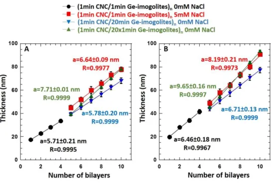
The following set-up was used to examine the effect of dipping parameters. The first four CNC/Ge-imogolite bilayers were coated according to the protocol described in the first part of the study (Figure 3A-B, black dots), while the following six bilayers were built by varying the dipping parameters (Figure 3A-B, blue, green, and red symbols). When no dipping parameters
were modified, the increments were 5.71±0.21 nm (Figure 3A), and 6.46±0.18 nm with short and long Ge-imogolites, respectively (Figure 3B).
The parameters that were varied for Ge-imogolite suspensions were as follows: - Dipping time (i),
- Ionic strength (ii),
- Immersion frequency/drying step (iii).
(i) Dipping times were adjusted on the basis of practical considerations. Nevertheless, they usually ranged from 10 to 20 min, but shorter times were used in some cases.14, 41 In this study, the chosen dipping time of the film in the nanoparticle suspensions was 1 min, Thus, the dipping time was increased up to 20 min to investigate the possible effect of slow kinetic or rearrangement processes (Figure 3, blue inverted triangles). No influence on the thickness increment was observed, indicating that very fast kinetic adsorption occurred. It could therefore be concluded that the final architecture of a CNC/Ge-imogolite-based thin film was not dependent on the dipping time.
Figure 3: Dipping parameter variations to find the optimal growth of: A) (CNC/short Ge-imogolite) and B) long (CNC/long Ge-Ge-imogolite) thin films.
(ii) Electrostatic repulsions between Ge-imogolite nanotubes adsorbed on the surface and/or present in solution could be responsible for the limited NP adsorption. The screening of electrostatic repulsions by increasing the ionic strength has been widely studied in the literature since it can increase adsorption by lowering electrostatic repulsion between NPs but also by changing the conformation of PE, which could promote the formation of denser NP layers. 42, 43 To avoid NP aggregation, a salt concentration of 5 mmol.L-1 was chosen at which short and long Ge-imogolites displayed an electrophoretic mobility of about 3 µm.cm.V-1.s-1 (vs 5-6 µm.cm.V
-1.s-1 without salt) (Figure SI6). A 0.93 nm and 1.73 nm thickness increment increase was
observed when short and long Ge-imogolites were used, respectively (Figures 3A and 3B, red squares). Thus, screening of the Ge-imogolite charges seemed to indicate an increase in the amount of NP adsorbed on CNC layers, but the increment expected (~10 nm), according to the
pattern noted with PE+NP thin films, was not reached. This effect could have been due to densification of the NP layer, as reported by Dammak et al.42 who noted a decrease in the porosity of CNC/xyloglucan multilayered films upon the addition of low concentrations of monovalent salt to the CNC suspension. From this work it was concluded that the screening of electrostatic repulsion allowed CNCs to pack more closely on the surface, which could explain the small thickness increment observed when NaCl was added to the Ge-imogolite suspensions. (iii) Finally, the immersion frequency in the Ge-imogolite suspensions was increased and each immersion was followed by drying of the layer by a nitrogen stream. Indeed, the effect of drying has already been reported to have a very strong effect on the film construction and stability.39 Here, a typical CNC/Ge-imogolite bilayer was composed of:
- A layer of CNC, which was coated by dipping the film for 1 min in the suspension. This step was followed by washing and drying,
- Twenty dipping steps by dipping the film 20*1 min in the Ge-imogolite suspension. Each 1 min immersion was followed by washing and drying.
When short Ge-imogolites were used (Figure 3A, green triangles), the increment increase of 2.00 nm (7.71±0.01 nm) and +3.19 nm (9.65±0.16 nm) when long Ge-imogolites (Figure 3B, green triangles) were used. In the case of long Ge-Imogolites, the increment is slightly smaller than the theoretical value in the case of close packing (12.05xcos(pi/6)=10.43 nm expected), suggesting only little spacing between particles. In the case of short Ge-Imogolites the increment is much lower than for a close-packing (11.55xcos(pi/6)=10.00 nm expected) suggesting a larger spacing between nanoparticles. However, the protocol enabled a significant increase of the increments.
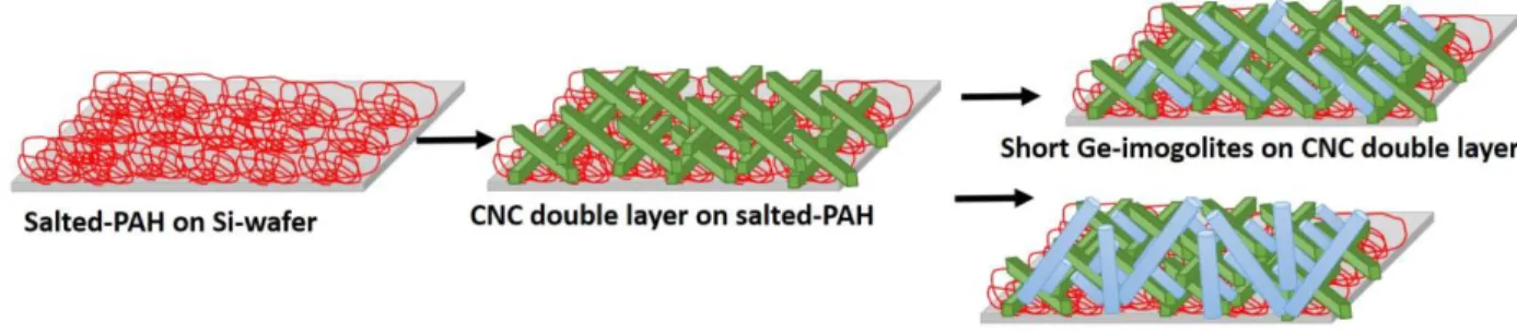
imogolite amount adsorbed. Electrostatic interactions occurred when Ge-imogolites were coated on a CNC layer. Nevertheless, both CNCs and Ge-imogolites were loosely charged materials compared to polymeric PE. Moreover, the stiffness of the particles limited the rearrangement of the architecture to increase the ion pairing as compared to more flexible polymeric PE. It was thus likely that during the adsorption step, the wet structure could be seen as a loose gel of NPs on the surface that was thick enough to allow the charge reversal. When the film was dried, the gel collapsed due to the removal of water and NPs flattened on the surface, but without complete coverage and complete compensation of charges arising from the n-1 layer. Thus a new dipping sequence allowed the adsorption of additional NPs leading to an increase in the film thickness to achieve a more complete layer.
To investigate the hypothesis of the influence of the drying step on a NP/NP thin film, CNC double layers were coated on PAH, and imaged by SEM. The first and twentieth coatings of Ge-imogolites were compared for the two the aspect ratios.
Figure 4: SEM investigation of the adsorption mechanisms of Ge-imogolites on CNC with the drying step.
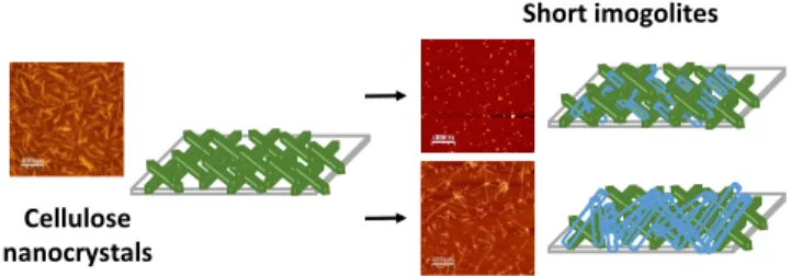
A non-metallized-CNC double layer is presented in Figure 4A. CNCs were hardly visible due to the insulating properties of CNC. A loose and porous layer appeared when long and short Ge-imogolites (Figure 4B-4D) were coated. Imogolites appeared as fiberlike networks and seemed to form bundles. This is consistent with the findings of a previous study showing the formation of these Ge-imogolite bundles when the suspension was dried at room temperature.44 However, the nature of the inter-tube interactions is not yet sufficiently understood to be discussed in detail in this study. This architecture has yet to be investigated and is probably a complex interplay between charge distributions along the tube and various interaction forces (e.g. capillary forces, electrostatic, hydrogen bonding). Nevertheless, obviously repetitive immersions in Ge-imogolites increase the amount of NPs (Figure 5C-5E) to achieve more complete surface coverage. A more in-depth AFM investigation of the surface morphologies was carried out.
Surface topography of the first bilayer CNC/Ge-imogolite.
The film topographies measured by AFM are presented in Figure 5. For each thin film (CNC bilayer (Figure 5A), short imogolite layer on a CNC double layer (Figure 5B), and long Ge-imogolite layer on a CNC double layer (Figure 5C)), a height profile is displayed. In addition, height profiles were integrated on the entire images.
Figure 5: AFM images on a 2 μm*2 µm area of: A) (PAH/NCC)1, B) (CNC/short
Ge-imogolites)1 on PAH, and C) (CNC/long Ge-imogolites)1 on PAH; specific profiles were
measured on 1 μm, and roughness distributions were evaluated on whole images.
Firstly, the CNC layer on PAH (Figure 5A) appeared as a dense layer, in accordance with previous results obtained for CNC from cotton linters on salted-PAH.39, 40 The average height profile displayed an unusual organization for a homogeneously distributed CNC layers that is
reminiscent of a double layer of CNCs already described in previous work. 39, 40 Indeed, the lower layer was denser than the surface layer. This result is in accordance with the architecture reported by Moreau et al. 39, and the CNC distribution described by Jean et al. by neutron reflectivity and AFM. 40 The authors noted that the CNC double layer deposited on PAH display a densities of 50% and 25% for the lower and upper layers, respectively. When short Ge-imogolites were added on CNC, the adsorption of NP was visually unclear (Figure 5B). The bimodal distribution profile changed and was less marked than for that with CNCs alone. This suggested that short Ge-imogolites filled pores between CNCs (Figure 6). Short Ge-imogolites had an average length of about 35 nm and a diameter of 4 nm, with an aspect ratio of 8.5. Previous studies have reported marked variations in the porosity of dense materials obtained from rod/fiberlike particles as a function of the aspect ratio. For example, as the aspect ratio of cylinders varied from 5 to 50, the porosity increased dramatically from 0.42 to 0.90. 45 CNCs and short Ge-imogolites could thus be more efficiently packed by co-alignment, in turn optimizing ion pairing and resulting in a charge reversal, but without the formation of a distinct Ge-imogolite layer, leading to a lower thickness increment than obtained with PE/Ge-Ge-imogolite systems.
Long Ge-imogolites appeared more clearly on the image as long and thin nanorods (Figure 5C). The bimodal distribution profile also changed and the first population was hardly distinguishable. Since long Ge-imogolites had a higher aspect ratio than short Ge-imogolites, a more porous structure with lower packing could be expected. In a first approximation, this seems to be out of line with the more homogeneous profile obtained. However, the tip penetration in the film must be taken into account. Since long Ge-imogolites could not efficiently fill holes in the
could thus limit the tip penetration, leading to a more homogeneous image profile. Nevertheless, it is obvious that aspect ratio of Ge-imogolites play a crucial role in the nanoparticle distribution in the film and, besides morphology changes, porosity should also be affected.
Figure 6: Schematic representation of the adsorption mechanism of Ge-imogolites on CNC as a function of the Ge-imogolite aspect ratio. Each film presented was considered to have been
washed and dried. CONCLUSION
In summary, we explored PE/NP-based multilayer film formation and demonstrated that CNC/Ge-imogolite-based multilayer films could be successfully formed. A first difference was found that all nanoparticle multilayered films grew differently than PE and NP based films. We showed that the growth of CNC/Ge-imogolite-based multilayer films was insensitive to some dipping parameters, such as ionic strength or dipping time, while repeated immersion/drying steps had an effect on film growth. We highlighted the essential effect of the drying step on the architecture of the final all nanoparticle multilayered films. AFM images demonstrated that the film architecture was dependent on the NP aspect ratio. The influence of architecture variations on the porosity and associated functionality of such optical or diffusion features will be investigated in future work.
TABLE OF GRAPHIC CONTENT
ASSOCIATED CONTENT
Supporting Information
Length and height distributions of CNC and Ge-imogolites, example of particles determination measurement, FTIR spectra of CNC and imogolites, film thickness patterns when only one of them was coated on a silicon wafer, electrophoretic mobility of Ge-imogolite suspensions as a function of NaCl addition, and structural colors obtain as a function layer deposition.
AUTHOR INFORMATION
Corresponding Author
*E-mail bernard.cathala@inra.fr (B.C.). *E-mail rose@cerege.fr (J.R.).
Notes
The authors declare no competing financial interest.
Funding Sources Cellulose
nanocrystals
Short imogolites
This work is a contribution to the Labex Serenade programme (no. ANR-11-LABX-0064) funded by the “Investissements d'Avenir” programme of the French National Research Agency (ANR) through the A*MIDEX project (no. ANR-11-IDEX-0001-02).
ACKNOWLEDGMENTS
We thank ad ge eur for her excellent technical support for LbL assembly and ellipsometry. We are also grateful to Andrea Campos from the CP2M laboratory for her SEM imaging technical support.
REFERENCES.
1. Wu, C. N.; Saito, T.; Fujisawa, S.; Fukuzumi, H.; Isogai, A. Ultrastrong and High Gas-Barrier Nanocellulose/Clay-Layered Composites. Biomacromolecules 2012, 13 (6), 1927-1932. 2. Aulin, C.; Salazar-Alvarez, G.; Lindstrom, T. High strength, flexible and transparent nanofibrillated cellulose-nanoclay biohybrid films with tunable oxygen and water vapor permeability. Nanoscale 2012, 4 (20), 6622-6628.
3. Svagan, A. J.; Samir, M.; Berglund, L. A. Biomimetic foams of high mechanical performance based on nanostructured cell walls reinforced by native cellulose nanofibrils.
Advanced Materials 2008, 20 (7), 1263-+.
4. Rowland, S. P.; Roberts, E. J. The nature of accessible surfaces in the microstructure of cotton cellulose. Journal of Polymer Science Part A-1: Polymer Chemistry 1972, 10 (8), 2447-2461.
5. Klemm, D.; Kramer, F.; Moritz, S.; Lindström, T.; Ankerfors, M.; Gray, D.; Dorris, A. Nanocelluloses: A New Family of Nature-Based Materials. Angewandte Chemie International
Edition 2011, 50 (24), 5438-5466.
6. Siqueira, G.; Bras, J.; Dufresne, A. Cellulosic Bionanocomposites: A Review of Preparation, Properties and Applications. Polymers 2010, 2 (4), 728-765.
7. Lavoine, N.; Desloges, I.; Dufresne, A.; Bras, J. Microfibrillated cellulose – Its barrier properties and applications in cellulosic materials: A review. Carbohydrate Polymers 2012, 90 (2), 735-764.
8. Nechyporchuk, O.; Belgacem, M. N.; Bras, J. Production of cellulose nanofibrils: A review of recent advances. Industrial Crops and Products 2016, 93, 2-25.
9. Habibi, Y.; Lucia, L. A.; Rojas, O. J. Cellulose Nanocrystals: Chemistry, Self-Assembly, and Applications. Chemical Reviews 2010, 110 (6), 3479-3500.
11. Decher, G. Fuzzy nanoassemblies: Toward layered polymeric multicomposites. Science
1997, 277 (5330), 1232-1237.
12. Cranston, E. D.; Gray, D. G. Morphological and Optical Characterization of
Polyelectrolyte Multilayers Incorporating Nanocrystalline Cellulose. Biomacromolecules 2006, 9 (7), 2522-2530.
13. Wagberg, L.; Decher, G.; Norgren, M.; Lindstrom, T.; Ankerfors, M.; Axnas, K. The Build-Up of Polyelectrolyte Multilayers of Microfibrillated Cellulose and Cationic
Polyelectrolytes. Langmuir 2008, 24 (3), 784-795.
14. Martin, C.; B., J. Nanocellulose/polymer multilayered thin films: tunable architectures towards tailored physical properties. Nord. Pulp Paper Res. J. 2014, 29 (1), 19-30.
15. Merindol, R.; Diabang, S.; Felix, O.; Roland, T.; Gauthier, C.; Decher, G. Bio-Inspired Multiproperty Materials: Strong, Self-Healing, and Transparent Artificial Wood Nanostructures.
Acs Nano 2015, 9 (2), 1127-1136.
16. Podsiadlo, P.; Sui, L.; Elkasabi, Y.; Burgardt, P.; Lee, J.; Miryala, A.; Kusumaatmaja, W.; Carman, M. R.; Shtein, M.; Kieffer, J.; Lahann, J.; Kotov, N. A. Layer-by-layer assembled films of cellulose nanowires with antireflective properties. Langmuir 2007, 23 (15), 7901-7906. 17. Podsiadlo, P.; Choi, S. Y.; Shim, B.; Lee, J.; Cuddihy, M.; Kotov, N. A. Molecularly engineered nanocomposites: Layer-by-layer assembly of cellulose nanocrystals.
Biomacromolecules 2005, 6 (6), 2914-2918.
18. Cerclier, C.; Lack-Guyomard, A.; Moreau, C.; Cousin, F.; Beury, N.; Bonnin, E.; Jean, B.; Cathala, B. Coloured Semi-reflective Thin Films for Biomass-hydrolyzing Enzyme
Detection. Advanced Materials 2011, 23 (33), 3791–3795.
19. Jean, B.; Heux, L.; Dubreuil, F.; Chambat, G.; Cousin, F. Non-Electrostatic Building of Biomimetic Cellulose-Xyloglucan Multilayers. Langmuir 2009, 25 (7), 3920-3923.
20. Cerclier, C.; Cousin, F.; Bizot, F.; Moreau, C.; Cathala, C. Elaboration of Spin-Coated Cellulose-Xyloglucan Multilayered Thin Films. Langmuir 2010, 26 (22), 17248–1725.
21. Olszewska, A.; Kontturi, E.; Laine, J.; Österberg, M. All-cellulose multilayers: long nanofibrils assembled with short nanocrystals. Cellulose 2013, 20 (4), 1777-1789.
22. Qi, Z.-D.; Saito, T.; Fan, Y.; Isogai, A. Multifunctional Coating Films by Layer-by-Layer Deposition of Cellulose and Chitin Nanofibrils. Biomacromolecules 2012, 13 (2), 553-558. 23. Martin, C.; Barker, R.; Watkins, E. B.; Dubreuil, F.; Cranston, E. D.; Heux, L.; Jean, B. Structural Variations in Hybrid All-Nanoparticle Gibbsite Nanoplatelet/Cellulose Nanocrystal Multilayered Films. Langmuir 2017, 33 (32), 7896-7907.
24. Levard, C.; Masion, A.; Rose, J.; Doelsch, E.; Borschneck, D.; Dominici, C.; Ziarelli, F.; Bottero, J. Y. Synthesis of Imogolite Fibers from Decimolar Concentration at Low Temperature and Ambient Pressure: A Promising Route for Inexpensive Nanotubes. Journal of the American
Chemical Society 2009, 131 (47), 17080-+.
25. Cradwick, P. D.; Wada, K.; Russell, J. D.; Yoshinaga, N.; Masson, C. R.; Farmer, V. C. Imogolite, a hydrated aluminum silicate of tubular structure. Nature-Physical Science 1972, 240 (104), 187-+.
26. Jiravanichanun, N.; Yamamoto, K.; Irie, A.; Otsuka, H.; Takahara, A. Preparation of hybrid films of aluminosilicate nanofiber and conjugated polymer. Synthetic Metals 2009, 159 (9), 885-888.
27. Jiravanichanun, N.; Yamamoto, K.; Yonemura, H.; Yamada, S.; Otsuka, H.; Takahara, A. Fabrication of conjugated polymer hybrid thin films with radially oriented aluminosilicate
nanofibers by spin-assembly. Bulletin of the Chemical Society of Japan 2008, 81 (12), 1663-1668.
28. Wada, S.; Wada, K. Effects of substitution of germanium for silicon in imogoloite. Clays
and Clay Minerals 1982, 30 (2), 123-128.
29. Rotoli, B. M.; Guidi, P.; Bonelli, B.; Bernardeschi, M.; Bianchi, M. G.; Esposito, S.; Frenzilli, G.; Lucchesi, P.; Nigro, M.; Scarcelli, V.; Tomatis, M.; Zanello, P. P.; Fubini, B.; Bussolati, O.; Bergamaschi, E. Imogolite: An Aluminosilicate Nanotube Endowed with Low Cytotoxicity and Genotoxicity. Chemical Research in Toxicology 2014, 27 (7), 1142-1154. 30. Liu, W.; Chaurand, P.; Di Giorgio, C.; De Meo, M.; Thill, A.; Auffan, M.; Masion, A.; Borschneck, D.; Chaspoul, F.; Gallice, P.; Botta, A.; Bottero, J.-Y.; Rose, J. Influence of the Length of Imogolite-Like Nanotubes on Their Cytotoxicity and Genotoxicity toward Human Dermal Cells. Chemical Research in Toxicology 2012, 25 (11), 2513-2522.
31. Maillet, P.; Levard, C.; Spalla, O.; Masion, A.; Rose, J.; Thill, A. Growth kinetic of single and double-walled aluminogermanate imogolite-like nanotubes: an experimental and modeling approach. Physical Chemistry Chemical Physics 2011, 13 (7), 2682-2689.
32. Avellan, A.; Levard, C.; Chaneac, C.; Borschneck, D.; Onofri, F. R. A.; Rose, J.; Masion, A. Accelerated microwave assisted synthesis of alumino-germanate imogolite nanotubes. Rsc
Advances 2016, 6 (109), 108146-108150.
33. Amara, M. S.; Paineau, E.; Bacia-Verloop, M.; Krapf, M. E. M.; Davidson, P.; Belloni, L.; Levard, C.; Rose, J.; Launois, P.; Thill, A. Single-step formation of micron long
(OH)(3)Al2O3Ge(OH) imogolite-like nanotubes. Chemical Communications 2013, 49 (96), 11284-11286.
34. Levard, C.; Rose, J.; Masion, A.; Doelsch, E.; Borschneck, D.; Olivi, L.; Dominici, C.; Grauby, O.; Woicik, J. C.; Bottero, J. Y. Synthesis of large quantities of single-walled
aluminogermanate nanotube. Journal of the American Chemical Society 2008, 130 (18), 5862-+. 35. Revol, J. F.; Bradford, H.; Giasson, J.; Marchessault, R. H.; Gray, D. G. Helicoidal Self-Ordering of Cellulose Microfibrils in Aqueous Suspension. International Journal of Biological
Macromolecules 1992, 14 (3), 170-172.
36. Gustafsson, J. P. The surface chemistry of imogolite. Clays and Clay Minerals 2001, 49 (1), 73-80.
37. Paineau, E.; Krapf, M. E. M.; Amara, M. S.; Matskova, N. V.; Dozov, I.; Rouziere, S.; Thill, A.; Launois, P.; Davidson, P. A liquid-crystalline hexagonal columnar phase in highly-dilute suspensions of imogolite nanotubes. Nature Communications 2016, 7.
38. Capron, I.; Cathala, B. Surfactant-Free High Internal Phase Emulsions Stabilized by Cellulose Nanocrystals. Biomacromolecules 2013, 14 (2), 291-296.
39. Moreau, C.; Beury, N.; Delorme, N.; Cathala, B. Tuning the Architecture of Cellulose Nanocrystal-Poly(allylamine hydrochloride) Multilayered Thin Films: Influence of Dipping Parameters. Langmuir 2012, 28 (28), 10425-10436.
40. Jean, B.; Dubreuil, F.; Heux, L.; Cousin, F. Structural Details of Cellulose
Nanocrystals/Polyelectrolytes Multilayers Probed by Neutron Reflectivity and AFM. Langmuir
2008, 24 (7), 3452-3458
41. Olivier, C.; Moreau, C.; Bertoncini, P.; Bizot, H.; Chauvet, O.; Cathala, B. Cellulose Nanocrystal-Assisted Dispersion of Luminescent Single-Walled Carbon Nanotubes for Layer-by-Layer Assembled Hybrid Thin Films. Langmuir 2012, 28 (34), 12463-12471.
42. Dammak, A.; Moreau, C.; Azzam, F.; Jean, B.; Cousin, F.; Cathala, B. Influence of cellulose nanocrystals concentration and ionic strength on the elaboration of cellulose
nanocrystals–xyloglucan multilayered thin films. Journal of Colloid and Interface Science 2015,
460, 214-220.
43. Azzam, F.; Moreau, C.; Cousin, F.; Menelle, A.; Bizot, H.; Cathala, B. Cellulose Nanofibril-Based Multilayered Thin Films: Effect of Ionic Strength on Porosity, Swelling, and Optical Properties. Langmuir 2014, 30 (27), 8091-8100.
44. Amara, M. S.; Rouziere, S.; Paineau, E.; Bacia-Verloop, M.; Thill, A.; Launois, P. Hexagonalization of Aluminogermanate Imogolite Nanotubes Organized into Closed-Packed Bundles. Journal of Physical Chemistry C 2014, 118 (17), 9299-9306.
45. Nan, W. G.; Wang, Y. S.; Liu, Y. W.; Tang, H. P. DEM simulation of the packing of rodlike particles. Advanced Powder Technology 2015, 26 (2), 527-536.