HAL Id: hal-00656450
https://hal.archives-ouvertes.fr/hal-00656450
Submitted on 4 Jan 2012
HAL is a multi-disciplinary open access
archive for the deposit and dissemination of
sci-entific research documents, whether they are
pub-lished or not. The documents may come from
teaching and research institutions in France or
abroad, or from public or private research centers.
L’archive ouverte pluridisciplinaire HAL, est
destinée au dépôt et à la diffusion de documents
scientifiques de niveau recherche, publiés ou non,
émanant des établissements d’enseignement et de
recherche français ou étrangers, des laboratoires
publics ou privés.
Self-adjusting, Isostatic Exoskeleton for The Human
Knee Joint
Viet Anh Dung Cai, Philippe Bidaud, Vincent Hayward, Florian Gosselin,
Eric Desailly
To cite this version:
Viet Anh Dung Cai, Philippe Bidaud, Vincent Hayward, Florian Gosselin, Eric Desailly.
Self-adjusting, Isostatic Exoskeleton for The Human Knee Joint. 33rd Annual International Conference of
the IEEE EMBS, Aug 2011, Boston, United States. pp.612-619. �hal-00656450�
Self-adjusting, Isostatic Exoskeleton for The Human Knee Joint
Viet Anh Dung Cai, Philippe Bidaud, and Vincent Hayward
UPMC
Univ Paris 06, Institut des Syst`emes Intelligents et de Robotique, Paris, France
{cai,bidaud,hayward}@isir.upmc.frFlorian Gosselin
Laboratoire de Robotique Interactive,
CEA, LIST, 92265 Fontenay-aux-Roses, France
Eric Desailly
Fondation Ellen Poidatz
Saint Fargeau-Ponthierry, France
[email protected]Abstract— A knee-joint exoskeleton design that can apply programmable torques to the articulation and that self-adjusts to its physiological movements is described. Self-adjustment means that the articular torque is automatically produced around the rotational axis of the joint. The requirements are first discussed and the conditions under which the system tracks the spatial relative movements of the limbs are given. If these conditions are met, the torque applied to the joint takes into account the possible relative movements of the limbs without introducing constraints. A prototype was built to demonstrate the applicability of these principles and preliminary tests were carried out to validate the design.
I. INTRODUCTION
Electro-mechanical systems used in functional rehabil-itation can increasingly contribute to modern therapeutic techniques. Such systems can be employed to assist the work of therapists, to increase the mobility of patients in daily activities, or to support various rehabilitation protocols. They can also provide quantifiable measurements to help the diagnosis and monitor therapeutic process.
According to M. Hillman [8], the first active orthoses ap-peared in the sixties. They were used to move the paralyzed limbs of a person and support gradual rehabilitation based on mechanically assisted exercises. It is only in the late nineties, however, that such systems became truly practical.
A. Related Work
Two different approaches in the design of mechanical devices for functional rehabilitation therapy or for diagnosis have emerged. The first approach involves the use of robotic arms to guide parts of the patient’s anatomy along predefined trajectories. The interaction between the driven member and the robotic arm often occurs near the extremity of the respective kinematic chains. Many systems dedicated to the rehabilitation of upper limb functions using this approach have been designed, such is the case of the MIT-Manus [9], of the MIME system [2], of the ‘Braccio di Ferro’ [4], or of the Nerebot system employing free-space wires [12].
Such an “external approach” yields systems that are easy to implement but can be problematic in terms of efficiency and security. The device may force the articulation of the subject to move in arbitrary directions, which can cause, for instance, hyper-extension. In addition, these devices engage
several joints simultaneously and do not allow to exercise individual joints. This limitation makes difficult diagnosis, treatment monitoring and joint-specific protocols.
The second approach involves engaging the joints indi-vidually. This function can be achieved by the coordinated control of multi-contact systems, often resulting in exoskele-ton mechanical structures. Several exoskeleexoskele-ton systems for upper limb rehabilitation have been proposed, including the Pneu-WREX [15], the Armin [13], the Dampace [18], or the Cadenas-7 [14].
These systems, however, typically come with an impor-tant limitation due to the misalignment between the patient joints and the active mechanical joints, which combined with hyperstaticity, result in a number of deleterious effects. The transmission of forces and torques is also difficult to manage since, generally speaking, the number of actuators never exceeds the mobility of anatomical joints. As a result, it becomes impossible to gain complete control over the transmitted forces and torques.
To address this problem, authors have proposed to employ mechanisms that transmit pure torques by means of properly designed mechanisms [6], [17]. For instance, a three-slider-joint followed by three actuated rotational three-slider-joints can provide such function. The transmission of pure torques to engage individual anatomical joint is the simplest solution that enables exoskeleton systems to operate safely.
B. A New Design
This article describes a novel active orthosis device. Its design is based on the determination of the number of passive degrees of freedom that the mechanism should have in order to become isostatically loaded when acting against a joint. A quasi-static analysis is employed to ensure a proper force transmission to the limbs in order to overcome muscular disturbances.
We built an active orthosis for the knee that provides a flexion-extension torque in order to exercise the joint, or to assist it’s movements. The device can also monitor the joint kinematics during movement through the estimation of the helical, instantaneous displacement axis [10], [20].
33rd Annual International Conference of the IEEE EMBS Boston, Massachusetts USA, August 30 - September 3, 2011
II. KINEMATICSOFTHEKNEE
The kinematics of human joints is complex, and the knee joint is no exception. The complicated relative movements of the limbs depend on the geometry of the joint surfaces, on the load, and on the properties of the ligaments, capsules, and menisci. Within subjects, the kinematics can also vary according to a variety of conditions [11] [19].
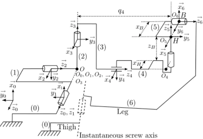
A description of the kinematics of the knee joint based on a six-degrees-of-freedom model composed from three screw joints was proposed by [5], see Fig. 1. Its use is nowadays recommended by the International Society of Biomechanics [21]. It comprises:
1) A rotational axis for the femur that passes through the centers of both femoral condyles. The joint displace-ments along this axis are named ’flexion–extension’ and ’medial–lateral’, respectively.
2) The axis of the tibia. The joint displacements along this axis is named ’internal rotation’ and ’proximal–distal displacement’.
3) The varus axis that is orthogonal to the first two axes. The joint displacements along this axis are named ’varus–valgus rotation’ and ’anterior–posterior displacement’.
Figures 2 and 3 show the results of previous kinematics measurements of the knee. These measurements were per-formed using a passive 6 DOFs electromechanical goniome-ter. Further details can be found in [3].
Fig. 1. Model of the knee joint by 6 degrees of freedom [5]. As we can see from Figure 3, the knee joint has a variable instantaneous axis during movement. Its location varies up to 2 centimeters during flexion due to anterior-posterior displacements. The varus–valgus and internal rotation angles vary up to 5∘ and 10∘. Notice also that the internal rotation angle can become active when the knee is in full flexion, and can vary up to 30∘.
These results highlight the fact that the knee is a spatial joint. For orthosis design, it should not be modeled as a hinge joint in flexion-extension. In an active or passive orthosis design, passive joints are crucial to free up the constraints due to the misalignment between the instantaneous rotation axes of the knee and that of the orthosis.
Fig. 2. The angular variation of the knee joint during flexion-extension movement. Calculations are done using the model of [5] illustrated in the figure 1.
Fig. 3. The instantaneous helical axis of the knee joint measured by an electro-goniometer [3]. Calculations are done between the moments Δ1and
Δ2 as shown in the figure 2.
III. DESIGNMETHOD
When the mechanism is fixed to the two limbs, it forms a closed kinematic chain with the anatomical joint. As will be demonstrated in section IV, if the device is properly designed, it mainly applies a torque around the knee joint. In these conditions, if the limbs fixations are properly designed, the muscle movements are limited and can be neglected in a first step. Then the mobility of the entire closed chain can be determined using
𝑚 = 𝑑(𝑏 − 1) − ∑
𝑖=1,𝑛
𝑢𝑖 (1)
where, 𝑚 is degree of mobility or degree of freedom of the mechanism, 𝑛 is number of elementary joints in the mechanism, 𝑑 is the dimension of the space in which the mechanism operates (𝑑 = 3, 6), 𝑏 is total number of bodies in the mechanism, including 1 fixed body and 𝑏 − 1 moving 613
bodies, and 𝑢𝑖 is number of elementary constraints in the
joint 𝑖.
When 𝑚 > 0, the mechanism is isostatic, the number of actuations required is equal to 𝑚. When 𝑚 ≤ 0, the mechanism becomes over-constrained. There is theoretically no possible movement of the mechanism, except in cases where a singularity appears, for example when the axis of rotation of the mechanism aligns with the articulation of the subject. This phenomenon can, in the best case, cause discomfort due to sliding movements of the attachments, and in the worst case, long term injury. If the torque provided by the system is significant, interaction with the device can cause pain. This problem has already been noticed by several authors [16], [17], [7].
Design rules for active functional rehabilitation devices can be established for an anatomical joint with 𝑘 mobilities, which satisfy the isostatic condition, see Table I.
TABLE I
DETERMINATION OF THE DOF’S AND ACTUATORS. Planar joint Spatial joint Total freedoms (𝑚) 𝑚 ≥ 3 𝑚 ≥ 6
Actuators (𝑎) 𝑎 = 𝑘 + 𝑚 − 3 𝑎 = 𝑘 + 𝑚 − 6 PassiveDOF’s 3 − 𝑘 6 − 𝑘
IV. DESCRIPTION OF THE KNEE EXOSKELETON The CAD model of our first knee exoskeleton prototype is shown in Fig. 4. The device comprises a total of 7 links forming a 6 degrees-of-freedom kinematic chain. The first three rotational joints are intersecting at point 𝑂. They are connected to a sliding joint that allows the mechanism to adapt to different limb sizes. The last two rotational joints are used to compensate for the offset between axes 2 and 3 and the axis of the tibia and the varus–valgus axis.
Fig. 4. The computer model of the knee exoskeleton The device can provide a torque of 40 Nm through the use of a brushless motor and a two-stages, backdrivable, 100:1 transmission. It comprises a high-speed friction drive followed by a low speed cable-drive. Each stage gives a torque gain equal to 10. The friction drive operates through
direct contact between the motor shaft and a disk drive, see Fig. 5. Contact is regulated by a compression spring pushing on rollers so that slip does not occur. This system allows for adjusting the slipping threshold, and thus provides an extra level of safety.
Fig. 5. View of the actuator unit
Each joint is equipped with a precision potentiometer. A force-torque sensor is inserted in the load path at the extremity of the mechanical chain for the control of force. Some links can be manually adjusted to optimize perfor-mance and ensure that the mechanical chain remains far from its singularities. Figure 6 shows the frame assignment of the system using the Denavit-Hartenberg convention. In the following sections, in order to facilitate analysis, all calculations are done in the reference frame 𝑅2.
Fig. 6. System frame assignment using the Denavit-Hartenberg notation.
A. Singularities
To determine the singular configurations, we write the Jacobian matrix at point 𝑂 in the frame 𝑅2, (𝑂, 𝑥2, 𝑦2, 𝑧2)
𝑱 (𝑶)𝑹2 = (𝑱𝒘1 𝑱 𝒘2 𝑱 𝒗1 𝑱 𝒗2 ) = ⎛ ⎜ ⎜ ⎜ ⎜ ⎜ ⎜ ⎝ 𝐶(𝑞2) 0 0 0 0 −𝑆(𝑞35) −𝑆(𝑞2) 0 −1 0 −1 0 0 1 0 0 0 𝐶(𝑞35) 0 0 0 −𝑆(𝑞3) 𝐽 𝑣15 𝐽 𝑣16 0 0 0 0 𝐽 𝑣25 𝐽 𝑣26 0 0 0 𝐶(𝑞3) 𝐽 𝑣35 𝐽 𝑣36 ⎞ ⎟ ⎟ ⎟ ⎟ ⎟ ⎟ ⎠ where 𝑞35= 𝑞3+ 𝑞5. The determinant of the matrix is
det(𝑱 (𝑶)𝑹2) = det ∣𝑱 𝒘1∣ det ∣𝑱 𝒗2∣
= − 𝑞4𝐶(𝑞2)(−𝑞4𝑆(𝑞5) + 𝑥𝐻𝐶(𝑞5) + 𝑥𝐵).
Singularities appear when det(𝑱 (𝑶)𝑹2) = 0, i.e. when,
𝑞4= 0, 𝑞2= ±𝜋/2, −𝑞4𝑆(𝑞5) + 𝑥𝐻𝐶(𝑞5) + 𝑥𝐵= 0.
If the mechanism is properly attached to the limbs (i.e. axis 𝒛1 close to the flexion axis after visual inspection) and if it
is correctly tuned (i.e. using the adjustments of links (0),(4) and (5). See Fig. 4 and Fig. 6), the principal movements are flexion and extension. The angle 𝑞2, which in this case
roughly corresponds to the internal rotation along the axis of the tibia, is then smaller than ±𝜋/2 and the length 𝑞4 is
greater than zero. The orthosis remains far from its singular positions during, except when 𝑞5is positive and much greater
than zero.
B. Force transmission
The force transmission analysis can be done by using the quasi-static model,
𝑻𝒋 = 𝑱⊤(𝑩)𝑻𝒆(𝑩) (2)
where 𝑇𝑗 is the vector of joint torques and forces, which in
our case is 𝑻𝒋 = (𝐶, 0, 0, 0, 0, 0)⊤, where 𝐶 is the motor
torque. The matrix 𝑱⊤(𝑩) is the transpose Jacobian of the system written at the point 𝐵 and 𝑻𝒆(𝑩) is the vector of
external torques and forces applied to the system at point 𝐵, which is defined by,
𝑻𝒆(𝑩) = ( 𝑴ext 𝑭ext ) = (𝑀𝑥, 𝑀𝑦, 𝑀𝑧, 𝐹𝑥, 𝐹𝑦, 𝐹𝑧)⊤. (3)
The knee movement mainly influences the movement of the first axis of rotation. The other mechanical joints of the orthosis only play a role of alignment between the first rotation axis and the instantaneous axis of the knee. As a result, they are close to zero. So the terms 𝑞2, 𝑞3, 𝑞5, 𝑞6may
be assumed to be close to zero. The matrix 𝑱⊤(𝑩), in the ideal case, becomes:
𝑱⊤(𝑩)𝑅 2 = ⎛ ⎜ ⎜ ⎜ ⎜ ⎜ ⎜ ⎝ 1 0 0 0 −𝑞4 −𝑧𝐵 0 0 1 𝑧𝐵 −𝑥𝐻− 𝑥𝐵 0 0 −1 0 −𝑞4 0 −𝑥𝐻− 𝑥𝐵 0 0 0 0 0 1 0 −1 0 0 0 −𝑥𝐵 0 0 1 0 0 0 ⎞ ⎟ ⎟ ⎟ ⎟ ⎟ ⎟ ⎠ . (4)
From (2), (3), and (4), we obtain the following system of equations, 𝐶 =𝑀𝑥− 𝑞4𝐹𝑦− 𝑧𝐵𝐹𝑧, 0 =𝑀𝑧+ 𝑧𝐵𝐹𝑥− (𝑥𝐻+ 𝑥𝐵)𝐹𝑦, 0 = − 𝑀𝑦− 𝑞4𝐹𝑥− (𝑥𝐻+ 𝑥𝐵)𝐹𝑧, 0 =𝐹𝑧, 0 = − 𝑀𝑦− 𝑥𝐵𝐹𝑧, 0 =𝑀𝑧.
The solution of this system of equations give us directly 𝑀𝑥 = 𝐶 and 𝑀𝑦 = 𝑀𝑧 = 𝐹𝑥 = 𝐹𝑦 = 𝐹𝑧 = 0. When
the mechanical chain is aligned with the knee instantaneous axis, only the motor torque is transmitted to the leg and there isn’t any residual force or torque transmitted.
In the general case, the six components of the external force vector expressed in the frame 𝑅2 are obtained from
the following expressions,
𝑀𝑦= 0, 𝐹𝑥= 0, 𝐹𝑧= 0, 𝐹𝑦= − 𝑀𝑧 𝐽 𝑣22 , 𝑀𝑧= 𝑀𝑥 𝑆(𝑞35) 𝐶(𝑞35) , 𝑀𝑥= 𝐶 𝐽 𝑣22𝐶(𝑞35) 𝐽 𝑣22𝐶(𝑞235) − 𝐽 𝑣21𝑆(𝑞35) .
where 𝑞35 = 𝑞3+ 𝑞5 and 𝑞235 = 𝑞2+ 𝑞3+ 𝑞5. 𝐽 𝑣22 and
𝐽 𝑣21 are terms of the Jacobian 𝐽 (𝐵) of the system written
at the point 𝐵. These force and torque components can then be expressed in frame 𝑅6 using the homogeneous matrix,
⎛ ⎝ 𝑀𝑥6 𝑀𝑦6 𝑀𝑧6 ⎞ ⎠ 𝑅6 = 𝑹62 ⎛ ⎝ 𝑀𝑥 0 𝑀𝑧 ⎞ ⎠ = ⎛ ⎝ 𝐶(𝑞35)𝑆(𝑞6)𝑀𝑥+ 𝑆(𝑞35)𝑆(𝑞6)𝑀𝑧 𝐶(𝑞35)𝐶(𝑞6)𝑀𝑥+ 𝑆(𝑞35)𝐶(𝑞6)𝑀𝑧 −𝑆(𝑞35)𝑀𝑥+ 𝐶(𝑞35)𝑀𝑧 ⎞ ⎠ ⎛ ⎝ 𝐹𝑥6 𝐹𝑦6 𝐹𝑧6 ⎞ ⎠ 𝑅6 = 𝑹62 ⎛ ⎝ 0 𝐹𝑦 0 ⎞ ⎠= ⎛ ⎝ −𝐹𝑦𝐶(𝑞6) 𝐹𝑦𝑆(𝑞6) 0 ⎞ ⎠.
The term −𝑆(𝑞35)𝑀𝑥+𝐶(𝑞35)𝑀𝑧= 0, i.e. the component
of the moment along the axis z6is equal to zero (𝑀𝑧6 = 0).
The component 𝑀𝑥6 is minimized when 𝑞6 is near to zero,
as for the component 𝐹𝑦6. Thus, there are essentially two
components (𝑀𝑦6, 𝐹𝑥6) which are transmitted to the leg.
According to our simulation results, when the motor transmits a torque of 15 Nm, this torque is essentially transmitted to the leg along the knee axis of rotation. A residual force around 30 N is also transmitted along the axis 𝑥6 perpendicular to the leg. This residual force may cause
slipping movements of the attachments with the thigh when the knee is in full flexion. Thus it should be minimized by adjusting the value 𝑞35 so that this latter is close to zero.
This is done by tuning the geometry of link (5) using the adjustments shown on Fig. 4.
A similar result is obtained for the analysis of force transmission on the thigh. In the ideal case where there is 615
no misalignment between the orthosis actuated axis and the knee instantaneous screw axis, two opposing torques of equal value are transmitted on the two limbs, thereby mobilizing the knee joint in flexion or in extension.
V. EXPERIMENTAL RESULTS
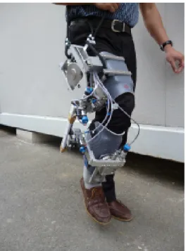
Fig. 7. View of the prototype.
Tests were carried out to validate the usability and perfor-mances of the device. We first implemented a robotized en-hancement of the static progressive stretch for the treatment of knee stiffness. Such exercise was originally designed to restore mobility of joints previously immobilized for a long postoperative period. In this experiment, instead of using a passive articulated splint [1], the device is used to pull the subject knee from an angular position to a new one. The subject was seated during the experiment.
Since there is no significant constraint on accuracy, a simple proportional controller was used to control the closed loop system. The actuation unit was controlled in torque to follow a reference trajectory 𝜃ref using a proportional
controller,
𝜏𝑝= −𝐾(𝜃measured− 𝜃ref). (5)
The reference trajectory is chosen to progressively stretch the knee joint. It can be e.g. a square or triangular 𝑞1signal
with growing amplitude. The total amount of torque applied on the system is equal to the sum of this virtual spring torque plus the user’s torque minus the resistance of the device measured by the force/torque sensor, hence the following control scheme:
To make the interaction ’orthosis-leg’ more natural, the system was controlled in practice by speed and not by torque. The virtual spring torque was set at 0.5 Nm/deg. The results of this experiments are shown in Figs. 9 and 10.
Fig. 8. Scheme of the control of the muscular stretching application.
Fig. 9. The resistance torque of the knee during stretching.
Fig. 10. The angular position and velocity of the actuated rotational axis of the orthosis during stretching.
The second test aimed at assisting the knee flexion and/or extension while the subject walked in a crouched or with a stiff knee gait. Such gaits frequently affect cerebral palsy children. Assisting the knee moment along quantified gait analysis may help to distinguish the part of the lack of muscle strength (or command) from the other possible causes of the gait deviation.
A torque control law was firstly implemented to allow an unconstrained knee motion to occur during the whole gait cycle (see Fig. 11). The interaction torque was minimized by setting the torque reference to zero (Fig. 12 and 13).
Fig. 11. Torque control scheme.
Fig. 12. Interaction torque between the mechanism and the leg during flexion-extension movement of the subject. (a) Result without force control. (b) Result with force control, the reference torque is set at zero.
Fig. 13. The velocity and angular position of the actuated rotational axis of the orthosis during the zero force interaction experience. (a) Result without force control. (b) Result with force control, the reference torque is set at zero.
algorithm detected the period during which the flexion move-ment occurs based on the estimation of the instantaneous
angular velocity of the actuated joint. Flexion torque could therefore be improved by using the torque control law with a torque reference greater than zero (see Table II). A triangular signal was used as the reference torque so that the transition between the empowering phase and the zero force movement tracking phase occurred as smoothly as possible.
TABLE II
ALGORITHM FOR DETECTION OF THE FLEXION MOVEMENT AND EMPOWERING STRATEGY.
—–—–—–—–———————————————————— Dispflex= 0; 𝜔last= 𝜔
Infinite Loop // Flexion estimation
Determine 𝜔
if (𝜔last> 0) and (𝜔 < 0) then
Dispflex= 0 endif
if (𝜔last< 0) and (𝜔 < 0) then
Dispflex= Dispflex+ 𝜔𝑇
endif
// Flexion movement detection and empowering of the movement if (Dispflex> thresholdflexion)
and (𝜔 < −𝜖) and (𝜃 > −𝜃max−flexion) then
𝜏ref= 𝜏flex// reference torque greater than zero
else
𝜏ref= 0 // movement tracking
endif
——————————————————————————–
Fig. 14. Interaction torque between the mechanism and the leg during flexion-extension movement of the subject. (a) Measured torque (b) Target torque.
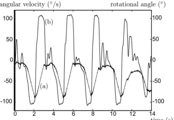
The results of these experiments are seen in Fig. 14 and 15. Even if the subject feels assisted by the torque provided by the orthosis during flexion of the latter, the interaction between the subject and the device is not sufficient during locomotion. We can observe in Fig. 15 that the rotational velocity of the orthosis is saturated. This in turn affects the angle of rotation which is very different from a natural one in our case. This problem could be solved by lowering the reduction ratio of the powering unit. This would decrease the maximum torque of the device but would increase its maxi-mum rotational velocity. Moreover, a more natural reference torque has to be identified from in-vivo experimental data. 617
Fig. 15. The angular position (a) and angular velocity (b) of the actuated rotational axis of the orthosis during the flexion empowering experience.
VI. CONCLUSION
In this paper, we presented an isostatic exoskeleton de-signed for the knee joint. An active prototype was built to validate this approach. The device has six degrees of freedom, one of which is actuated. It drives the knee flexion-extension by transmitting two opposed torques to the two limbs of the user. The first experiments provide encouraging results, considering both transparent mode during which a zero interaction torque is controlled and assistance mode during which the device is used to activate the knee as a function of the subject’s resistant torque.
Efforts should be made to improve the interaction between the device and the subject during very fast movements for a possible application of assistance to flexion/extension dur-ing walkdur-ing. The maximum rotational velocity in particular should be improved.
REFERENCES
[1] P.M. Bonutti, M.S. McGrath, S.D. Ulrich, S.A. McKenzie, T.M. Seyler, M.A. Mont, Static progressive stretch for the treatment of knee stiffness, The Knee, Vol. 15, Issue 4, 2008, pp 272-276.
[2] C.G. Burgar and P.S. Lum and P.C. Shor and H.F.M. Van der Loos, Development of robots for rehabilitation therapy : The Palo Alto VA/Stanford experience, Journal of Rehabilitation Research and Development, vol. 37, Num. 6, 2000, pp 663-673.
[3] V.A.D. Cai and B. Bru and P. Bidaud and V.Hayward and F. Gosselin and V. Pasqui, Experimental Evaluation of a Goniometer For the Iden-tification of Anatomical Joint Motions, Proceedings of the Thirteenth International Conference on Climbing and Walking Robots and the Support Technologies for Mobile Machines, CLAWAR 2010. [4] M. Casadio and V. Sanguinetia and P.G. Morassoa and V. Arrichiellob,
A new haptic workstation for neuromotor rehabilitation, Technology and Health Care - IOS Press, Num. 14, 2006, pp 124-142. [5] E.S. Grood and J.W. Suntay, A Joint Coordinate System for the
Clinical Description of Three-Dimensional Motions: Application to the Knee, Journal of Biomechanics, vol. 105, 1983, 136-144. [6] N. Jarrasse and G. Morel. A Methodology To Design Kinematics Of
Fixations Between An Orthosis And A Human Member. Proceedings of the IEEE/ASME International Conference on Advanced Intelligent Mechatronics AIM’09, 2009, pp. 1958–1963
[7] N. Jarrass´e and G. Morel, Formal Methodology for Avoiding Hyper-staticity When Connecting an Exoskeleton to a Human Member, IEEE International Conference on Robotics and Automation (ICRA’10), 2010.
[8] M. Hillman, 2 Rehabilitation robotics from past to present - a historical perspective, Lecture Notes in Control and Information Sciences, vol. 306, 2004, pp 25-44.
[9] N. Hogan and H.I. Krebs and J.Charnnarong and P. Srikrishna and A. Sharon, MIT - MANUS : A Workstation for Manual Therapy and Training I, IEEE International Workshop on Robot and Human Communication, 1992, pp 161-165.
[10] G.L. Kinzel and A.S. Hall and B.M. Hillberry, Measurement of the total motion between two body segments - I. Analytical development, Journal of Biomechanics, vol. 5, 1972, pp 93–105.
[11] K.L. Markolf and A. Kochan and H.C. Amstutz, Measurement of knee stiffness and laxity in patients with documented absence of the anterior cruciate ligament, The Journal of Bone and Joint Surgery, vol. 66, 1984, pp 242-252.
[12] S. Masiero and A. Celia and G. Rosati and M. Armani, Robotic-Assisted Rehabilitation of the Upper Limb After Acute Stroke, Arch Phys Med Rehabil, vol. 88, 2007, pp 142-149.
[13] T. Nef and M. Mihelj and R. Riener, ARMin II – 7 DoF rehabilitation robot: mechanics and kinematics, 2007 IEEE International Conference on Robotics and Automation, 2007, pp 4120-4125.
[14] J. Perry and J. Rosen and S. Burns, Upper-limb powered exoskeleton design, IEEE-ASME Trans. Mech., vol. 12, Num. 4, 2007, pp 408-417. [15] R.J. Sanchez and E. Wolbrecht and R. Smith and J. Liu and S. Rao and S. Cramer and T. Rahman and J.E. Bobrow and D.J. Reinkensmeyer, A Pneumatic Robot for Re-Training Arm Movement after Stroke: Rationale and Mechanical Design, Proceedings of the 2005 IEEE 9th International Conference on Rehabilitation Robotics, 2005, pp 500-504.
[16] A. Schiele and F.C.T van der Helm, Kinematic Design to Improve Ergonomics in Human Machine Interaction, IEEE Transactions on Neural Systems and Rehabilitation Engineering, vol. 14, 2006, pp 456-469.
[17] A.H.A. Stienen and E.E.G. Hekman and F.C.T. van der Helm and and H. van der Kooij, Self-Aligning Exoskeleton Axes Through Decoupling of Joint Rotations and Translations, IEEE Transaction On Robotics, vol. 25, 2009, pp 628-633.
[18] A.H.A. Stienen and E.E.G. Hekman and F.C.T. van der Helm and G.B. Prange and M.J.A. Jannink and A.M.M. Aalsma and H. van der Kooij, Dampace: Design of an Exoskeleton for Force-Coordination Training in UpperExtremity Rehabilitation, Journal of Medical Devices -Transaction on ASME, vol. 3, 2009.
[19] J. Winsman and F. Veldpaus and J. Janssen and A. Huson and P. Struben, A three-dimensional mathematical model of the knee-joint, Journal of Biomechanics, vol. 13, 1980, pp 677-685.
[20] H.J. Woltring and R. Huiskes and A. De Lange, Finite centrode and helical axis estimation from noisy landmark measurements in the study of human joint kinematics, Journal of Biomechanics, vol. 18, num. 5, 1985, pp 379-389.
[21] G. Wu and F.C.T. van der Helm and H.E.J. (DirkJan) Veeger and M. Makhsous and P.V. Roy and C. Anglin and J. Nagels and A.R. Karduna and K. McQuade and X. Wang and F.W. Werner and Bryan Buchholz, ISB recommendation on definitions of joint coordinate systems of various joints for the reporting of human joint motionPart II: shoulder, elbow, wrist and hand, Journal of Biomechanics, vol. 38, 2005, 981-992.
![Fig. 1. Model of the knee joint by 6 degrees of freedom [5].](https://thumb-eu.123doks.com/thumbv2/123doknet/13604763.424265/3.918.483.822.79.339/fig-model-knee-joint-degrees-freedom.webp)