Publisher’s version / Version de l'éditeur:
Vous avez des questions? Nous pouvons vous aider. Pour communiquer directement avec un auteur, consultez la première page de la revue dans laquelle son article a été publié afin de trouver ses coordonnées. Si vous n’arrivez pas à les repérer, communiquez avec nous à PublicationsArchive-ArchivesPublications@nrc-cnrc.gc.ca.
Questions? Contact the NRC Publications Archive team at
PublicationsArchive-ArchivesPublications@nrc-cnrc.gc.ca. If you wish to email the authors directly, please see the first page of the publication for their contact information.
https://publications-cnrc.canada.ca/fra/droits
L’accès à ce site Web et l’utilisation de son contenu sont assujettis aux conditions présentées dans le site LISEZ CES CONDITIONS ATTENTIVEMENT AVANT D’UTILISER CE SITE WEB.
ACS Applied Materials & Interfaces, 12, 39, pp. 43992-44006, 2020-06-12
READ THESE TERMS AND CONDITIONS CAREFULLY BEFORE USING THIS WEBSITE. https://nrc-publications.canada.ca/eng/copyright
NRC Publications Archive Record / Notice des Archives des publications du CNRC :
https://nrc-publications.canada.ca/eng/view/object/?id=c5510400-c0ec-4f77-b6ed-335c0e0b59f1 https://publications-cnrc.canada.ca/fra/voir/objet/?id=c5510400-c0ec-4f77-b6ed-335c0e0b59f1
NRC Publications Archive
Archives des publications du CNRC
This publication could be one of several versions: author’s original, accepted manuscript or the publisher’s version. / La version de cette publication peut être l’une des suivantes : la version prépublication de l’auteur, la version acceptée du manuscrit ou la version de l’éditeur.
For the publisher’s version, please access the DOI link below./ Pour consulter la version de l’éditeur, utilisez le lien DOI ci-dessous.
https://doi.org/10.1021/acsami.0c07179
Access and use of this website and the material on it are subject to the Terms and Conditions set forth at
Synthesis and characterization of zinc phthalocyanine-cellulose nanocrystal (CNC) conjugates: toward highly functional CNCs
Alam, Kazi M.; Kumar, Pawan; Gusarov, Sergey; Kobryn, Alexander E.; Kalra, Aarat P.; Zeng, Sheng; Goswami, Ankur; Thundat, Thomas; Shankar, Karthik
1
Synthesis, characterization and modeling the fluorescent zinc
phthalocyanine−cellulose nanocrystal conjugates: Towards highly functional
CNCs
Kazi M. Alam
1*, Pawan Kumar
1, Sergey Gusarov
,2Alexander E. Kobryn
,2Aarat P.
Kalra
1, 3, Sheng Zeng
1, Ankur Goswami
1, 4, Thomas Thundat
5, 6, and Karthik Shankar
1*1Department of Electrical & Computer Engineering, University of Alberta, 9211-116 St., Edmonton, AB T6G 1H9, Canada
2Nanotechnology Research Centre, National Research Council Canada, 11421 Saskatchewan Drive, Edmonton, AB T6G 2M9, Canada
3
Department of Physics, Faculty of Science, University of Alberta, Edmonton, T6G 1H9, Canada 4
Department of Materials Science and Engineering, Indian Institute of Technology Delhi, New Delhi 11016, India 5
Department of Chemical and Materials Engineering, University of Alberta, Edmonton, T6G 1H9, Canada 6
Department of Chemical and Biological Engineering, University at Buffalo, The State University of New York, Buffalo, New York 14260, USA
*
Corresponding authors: kshankar@ualberta.ca, kmalam@ualberta.ca
Abstract
We report the formation of highly fluorescent cellulose nanocrystals (CNCs) formed by conjugating a carboxylated zinc phthalocyanine (ZnPc) to two different types of CNCs. Negatively charged CNCs produced by concentrated sulfuric acid hydrolysis of wood pulp and CNCs (AI-CNCs) partially neutralized by NaOH treatment i.e. sodiated CNCs (Na-CNCs) were used to form conjugates with ZnPc. The conjugated nanocrystals (henceforth called ZnPc@CNCs) were a bright green in color and exhibited absorption and emission maxima at 690 nm and 715 nm respectively. The esterification protocol employed to covalently bind carboxylated ZnPc to surface hydroxyl group rich CNCs was expected to result in a monolayer of ZnPc on the surface of the CNCs. However, dynamic light scattering (DLS) studies indicated a large increase in the hydrodynamic radius of CNCs following conjugation to ZnPc,
2
which suggests the binding of multiple ZnPc molecular layers on the CNC surface. This binding could be through co-facial π-stacking of ZnPc, where ZnPc metallophthalocyanine rings are horizontal to the CNC surface. The other possible binding mode would give rise to conjugated systems where ZnPc metallophthalocyanine rings are oriented vertically on the CNC surface. Na-CNCs which have a lower density of free −OH groups showed a smaller increase in hydrodynamic radius compared to AI-CNCs, which have a larger density of free −OH groups on their surface. Both conjugates ZnPc@AI-CNC and ZnPc@Na-CNC showed long-lived charge separation following illumination with light. Density functional theory-based calculations showed stable geometry following the conjugation protocol that involved covalent ester bond formation. The conjugates demonstrated superior performance for the sensing of volatile organic compounds through higher photoluminescence quenching of NO2 compared
to pristine ZnPc. These results open up or bolster applications for CNCs in areas such as gas sensing, bioimaging, and photodetection while also providing more diagnostic tools to advance the characterization of CNCs- and CNC-based nanocomposites.
Key words: photoluminescence, biodegradability, sustainable technologies, surface functionalization,
KPFM, photoluminescence quenching, DFT, HOMO, LUMO, PDOS, VOC gas sensing.
1. Introduction
Cellulose nanocrystals (CNCs) are ~ 100 nm long rod-shaped crystalline particles consisting of linear polymerized chains of (1,4) linked β-D-glucopyranosyl units.1 CNCs are synthesized at scale from lignocellulosic biomass through a variety of mechanical and chemical treatments.2 CNCs are non-toxic, biodegradable, transparent, strongly hydrophilic with a high surface density of hydroxyl groups and mechanically robust, due to which they have been used by themselves in applications such as emulsion stabilizers,3 drug delivery (after coating with a suitable encapsulating agent),4 pH sensing,
3
chemobiological sensing using surface enhanced Raman scattering (following coating with Ag nanoparticles),5 as host matrices and waveguide materials for luminescent solar concentrators,6 polarization modulating thin films,7 etc. Despite the aforementioned promising applications in sensing, drug delivery and optics, the largest commercial potential of CNCs is widely agreed to lie in the field of polymer nanocomposites. CNCs have a range of mechanical attributes – low density (~ 1.6 g cm-2), high Young’s modulus (~ 10 GPa), high surface to volume ratio (> 500 m2 g-1), low coefficient of thermal expansion, piezoelectric response8 and high aspect ratio, that make them compelling candidates for blending with various industrial polymers to form functional nanocomposites. Indeed, nanocomposites of CNCs with many different polymers e.g. polyethylene, polypropylene, polyacrylamide, polyurethane, polyvinyl alcohol, polyvinyl acetate, polylactic acid, polydimethylsiloxane, polyacrylonitrile, PEDOT:PSS, etc. have been demonstrated with the purpose of using them in reinforced epoxies,9-10 reinforced construction and packaging materials,11-12 microelectromechanical strain sensors,13 stimulus-responsive hydrogels,14-16 water purification membranes,17 conductive inks and substrates,18 and so on. The commercialization and further engineering of CNC−polymer nanocomposites are severely constrained by a number of materials compatibility issues including, but not limited to, inhomogeneous dispersion of CNCs in polymer matrices, weak CNC-matrix interactions, inadequate understanding of the effect of processing on final performance, and unusual and unexpected rheological properties of CNC-polymer nanocomposites.19 There also exist a number of characterization challenges relating to CNC-polymer nanocomposites that limit analysis and solution-generation to the materials compatibility issues listed above. For instance, electron microscopy techniques, which are a staple of morphological characterization for inorganic nanomaterials, do not provide a clear indication of the internal structure of CNC-polymer nanocomposites due to insufficient contrast between the CNC and the polymer matrix. The predominance of weak van der Waals interactions between the filler (bare/functionalized CNCs)
4
and the matrix (polymer) result in spectroscopic techniques (Raman, FTIR, XPS, etc.) failing to pick up distinctive signatures of binding between the CNCs and polymer chains.20 In this regard, photoluminescence (PL)-based techniques such as fluorescence microscopy, total internal reflection fluorescence imaging (TIRF), fluorescence lifetime imaging microscopy (FLIM), etc. could be valuable in describing the internal structure of CNC-polymer nanocomposites using CNCs conjugated to fluorescent labels. Likewise, advanced scanning probe microscopic (SPM) techniques could be particularly beneficial in mapping out the relevant physical properties (e.g. charge, potential, adhesion force, etc.) of CNC-polymer nanocomposites. A major goal of this study was to synthesize highly fluorescent CNCs that would enable such PL-based and potential mapping-based characterization. Zinc phthalocyanine (ZnPc) is a member of the metalloporphyrin family of compounds. ZnPc contains extended intramolecular conjugation in a metal complexed heteroaromatic system with 18 delocalized π-electrons that confer a remarkably high oscillator strength for electronic transitions.21
ZnPc is also highly photoluminescent, with PL quantum yields as high as 30 % reported for specific moieties and solvents.22-23 The oxidative and thermal stability of ZnPc derivatives due to the aza-nitrogens and peripheral fused benzene rings render them less vulnerable to photobleaching.24 ZnPc and related compounds have been shown to work as optical limiters for use in mode locked lasers and nonlinear optical devices,25 as chemiresistive and fluorescent gas sensors,26-27 as active layers in photovoltaic devices,28 as hole transport layers in organic light emitting diodes29 and in photodynamic therapy.30 The formation of ZnPc-CNC conjugates with the concomitant advantages of mechanical robustness, structural and optical anisotropy, biodegradability, non-toxicity, etc. generated by cellulose nanocrystals presents the potential for CNCs to be used in some or all of the aforementioned applications.
5
The combination of a high absorption coefficient and an appreciable PL quantum yield results in ZnPc-containing molecules being very bright, long-lived chromophores for imaging applications. The primary target for such imaging capabilities is the multi-billion dollar market for fluorescent labels and biological contrast agents, which is currently dominated by PEGylated small molecule dyes, inorganic semiconductor quantum dots and gold nanoparticles.31-32 The low toxicity, low cost and earth abundance of both phthalocyanines (common textile colorants) and cellulose nanocrystals make ZnPc-CNCs a potentially intriguing candidate for bioimaging applications. ZnPc-CNCs also provide tremendous advantages in advancing the fundamental structural and interfacial characterization of CNC-based nanocomposites through PL- and SPM-based techniques as previously mentioned. In this communication, we report fabrication and characterization of highly fluorescent CNCs conjugated with octacarboxylated zinc phthalocyanine ZnPc. Density functional theory calculations showed stable geometry of conjugates and revealed electronic properties conducive to myriads of potential applications. The pristine ZnPc and the ZnPc conjugates with AI-CNCs and Na-CNCs were tested in molecular sensing application through photoluminescence quenching phenomenon, using nitrobenzene as a PL quencher.
2. Experimental Section
2.1 Materials
Cellulose nanocrystals were supplied by Alberta Innovates (InnoTech Alberta, Edmonton, Canada) and FP Innovations. Plain glass slides were purchased from Corning Inc. while conductive Tec 8 substrates consisting of fluorine-doped tin oxide (FTO) on glass, were purchased from Hartford Tec Glass company. Before usage, both types of glass substrates were sequentially cleaned using surfactant, water and isopropanol. Analytical grade Pyromellitic dianhydride, PMDA (97%), urea (98%), zinc acetate, (CH3COO)2Zn (99.98%), KOH (90%), H2SO4 (96%), thionyl chloride (SOCl2), 1 M soln. in
6
dichloromethane were procured from Alfa Aesar. Ammonium heptamolybdate tetrahydrate (99.98%), N, N-dimethylformamide, DMF (99.8%) were indented from Sigma Aldrich and used without further purification. All other solvents were of HPLC grade. Deionized (DI) water was used throughout the experiments.
2.2 Sample Preparation
CNC whiskers were obtained from Alberta Innovates in solid form and will be henceforth called AI-CNCs while sodiated AI-CNCs were obtained from FP Innovations and will be henceforth called Na-AI-CNCs. Clear non-turbid suspensions of five kinds of nanoparticles (bare AI-CNCs, bare Na-CNCs, bare ZnPc, ZnPc@AI-CNC and ZnPc@Na-CNC) with concentrations of ~ 2 mg ml-1 were prepared by dispersing the CNCs in deionized water using probe sonication for 2 h in ice bath. A diluted dispersion (~ 0.2 mg ml-1) was used for UV-Vis, PL, DLS and KPFM measurements. A 30 μL droplet was drop casted from concentrated aqueous dispersions on plain glass substrates and also on FTO/glass substrates.
2.3 ZnPc synthesis and conjugation protocol
2.3.1 Synthesis of zinc 2,3,9,10,16,17,23,24 octacarboxyphthalocyanine (or octacarboxylated phthalocyanine), ZnPc-(COOH)8: For the synthesis of zinc octacarboxylated phthalocyanine, a
microwave assisted solid-state synthesis protocol was followed.33-34 In brief, pyromellitic dianhydride, PMDA (4.0 g, 18.3 mmol), urea (20.8 g, 0.34 mol), zinc acetate (CH3COO)2Zn (6.78 g, 36.9 mmol), and
catalytic amount of ammonium heptamolybdate tetrahydrate (0.2 g) was ground in a mortar. The mixture was transferred in a glass beaker and covered loosely with a glass lid. The content of beaker was irradiated under microwave using a household microwave oven operating at 480 W for 10 min. During course of reaction the colour of mixture changed from purple to green to black. Cyclic polymerization of PMDA under microwave, metal and urea produce metal phthalocyanine cyclic imide. The obtained black solid was crushed well and washed with water and acetone several times and dried to remove
7
unreacted PMDA and urea. In the next step, the dried material was stirred in 6M HCl and supernatant liquid was decanted. This step is repeated several times to remove unreacted materials (salt/metal). The obtained cyclic imide was hydrolyzed to potassium salt of zinc octacarboxyphthalocyanine in 10% KOH (250 mL) aqueous solution at 85 °C with stirring for 8h. The resulting solution was cooled and diluted with 100 mL water, followed by filtration. The filtrate was acidified with concentrated HCl to pH-3 to convert potassium salt into free carboxylic acid group. The zinc octacarboxyphthalocyanine get precipitated as flocculant solid at the bottom. The obtained crude ZnPc-(COOH)8 was washed several
times with distilled water and finally with acetone followed by centrifugation at each step and dried under vacuum at room temperature to get ZnPc-(COOH)8. The subsequent discussion will refer to
ZnPc-(COOH)8 simply as ZnPc.
2.3.2 Synthesis of zinc 2,3,9,10,16,17,23,24 octacarbonylchloride phthalocyanine, ZnPc-(COCl)8:
Carboxylic acid groups in ZnPc-(COOH)8 have limited reactivity towards the -OH group. So, -COOH
present on zinc octacarboxyphthalocyanine groups were transformed into activated acyl chloride group by treatment with thionyl chloride (SOCl2). Briefly, ZnPc-(COOH)8 was grounded well in mortar and
the obtained powder was treated with excess of SOCl2, 1 M solution in CH2Cl2 with stirring for 1 h at
room temperature.35 Subsequently, the obtained zinc octacarbonylchloride phthalocyanine, ZnPc-(COCl)8 was separated from solution by decantation dried under vacuum and used immediately for the
further steps or stored under desiccator for later use.
2.3.3 Synthesis of covalently functionalized cellulose nanocrystals-zinc phthalocyanine conjugate (ZnPc-CNCs): The covalent functionalization of CNCs with ZnPc was achieved by taking advantage of the abundant -OH functional groups on CNCs and activated -COCl group on ZnPc-(COCl)8 which react
together to form ester linkage (-COO-). In general, a calculated amount of CNCs were dispersed in anhydrous DMF by using probe sonication for 6h. The obtained suspension was transferred in a round
8
bottom flask and 10 wt% ZnPc-(COCl)8 and 1 mL of triethyl amines (to extract formed HCl from the
reaction) was added. The content of RB flask was stirred at 130 °C for 12 h under nitrogen atmosphere. After cooling to room temperature, afforded ZnPc-CNCs suspension was centrifuged and washed with DMF to remove unreacted ZnPc, followed by washing with methanol and drying under vacuum conditions.
2.4 Sample characterization
To elucidate the chemical structure of ZnPc and ZnPc-CNCs conjugates (ZnPc@AI-CNC and ZnPc@Na-CNC), 1H NMR spectra of materials were measured by using a Varian Inova NMR spectrometer. The samples were dispersed in DMSO-d6 by sonication and spectra were measured using
tetramethylsilane (TMS) as the internal standard. Raman active vibrational modes of the materials were executed on a Raman spectrometer (Nd:YAG laser Raman Microscope, Nicolet Omega XR) using the 532 nm laser excitation line with an incident power of 8 mW cm−2. The samples were deposited on a glass slide and spectra was accumulated for 120 s using a 50 µm confocal pinhole apertures slit, with a 2 cm-1/CCD pixel element spectral dispersion grating. The absorption properties of DMF dispersed pristine octacarboxy zinc phthalocyanine and ZnPc conjugated CNCs in UV-Vis region were determined using a Perkin Elmer Lambda-1050 UV–Vis-NIR spectrophotometer in a quartz cuvette. The crystalline nature and phase structure of materials before and after functionalization were determined by X-ray powder diffraction (XRD) spectra acquired on a Bruker D8 advance diffractometer (XRD). This instrument uses Cu-Kα, IμSμ radiation (40 kV, λ = 0.15418 nm) equipped with a 2D detector
(VANTEC-500). To acquire spectra a scan size of 0.02° in the range of 2θ value 5–85° was used. Dynamic light scattering (DLS) was also used to obtain insights into the morphology of the nanoparticles. DLS was performed using a Nano-ZetaSizer (Malvern Instruments) instrument. The incident laser wavelength used was 633 nm, and the instrument automatically set detector angle using particle size in solution.
9
Data acquisition was performed in triplicate in order to maintain statistical significance. Within the DLS measurement file, the native conditions of the solution itself were used. Thus, for samples dissolved in water, the solvent was set to water, and the refractive index of 1.33 was used. The temperature of the system was set to 25° for each measurement. The morphological attributes of samples were determined using field emission scanning electron microscope, on a Hitachi S-4800 FESEM operating at an accelerating voltage 3 kV with a cold field emission electron source. The fine structural and elemental analysis of the ZnPc conjugated CNCs were performed using a JEOL JEM-ARM200CF, which is equipped with a cold Field-Emission Gun, a probe Cs corrector, and a fast EDX chemical mapping detector. The data were acquired at an acceleration voltage of 200 kV. For EDX elemental analysis scanning TEM (STEM) mode was employed. HRTEM (high resolution TEM) files (.dm3) were analysed with Gatan micrograph to obtain the lattice spacings.
Steady state photoluminescence (PL) spectra of samples were acquired on Varian Cary Eclipse fluorimeter using a xenon lamp excitation source by keeping 5 nm slit width. To investigate the nature of charge carrier generation/transport mechanism the surface potential (SP) change of materials were determined under different wavelength light using peak force Kelvin probe force microscopy (KPFM) on a Dimension Fast Scan Atomic Force microscope (Bruker Nanoscience Division, Santa Barbara, CA, USA). The CNCs/ZnPc-CNCs samples dispersed in DMF, were drop-casted on FTO glass followed by drying. The measurement was performed under dark and irradiation condition using 450 nm, 520 nm and 635 nm diode lasers (Thorlabs) that orthogonally illuminated samples on a custom-made optical setup. For parameters of the measurements were a SCM-PIT cantilever of 4.4 N/m stiffness, operating at 75nm nm lift height, 2 kHz lock-in bandwidth and scan speed of 1 Hz. Prior to measurements samples were grounded with the AFM chuck using a conductive copper tape and surface potential was mapped by sample routing at zero tip bias. The samples were kept under dark and light conditions for 5 min, to
10
achieve charge transport’s equilibrium condition. The work function of Pt-Ir tip (Φ) was calibrated by measuring the contact potential difference (CPD) of HOPG and the Pt tip and found to be 5.04 eV. The binding energy and oxidation states of various elements present in the materials to determine the surface/subsurface chemical composition of materials (~10 nm) was measured using X-ray photoelectron spectroscopy (XPS) using Axis-Ultra, Kratos Analytical instrument equipped with monochromatic Al-Kα source (15 kV, 50 W; photon energy 1486.7 eV) under ultrahigh vacuum (∼10−8
Torr). The binding energy of adventitious hydrocarbon C1s at ≈ 284.8 eV was used as standard (carbon correction) to assign the binding energy of other elements. The system generated raw data in .vms file was deconvoluted into various peak components using CasaXPS and obtained data were finally plotted in origin 8.5.
2.5 Photoluminescence quenching test
Photoluminescence (PL) quenching test experiments for the pristine ZnPc and ZnPc conjugated CNCs (AI-CNC and Na-CNC) were carried out using nitrobenzene as a fluorescence quencher. All the experiments were conducted in liquid state. Briefly, dilute solutions of ZnPc and ZnPc conjugated CNCs were prepared separately with known concentration in DMF. The steady state PL data were collected for each pristine material followed by a bimolecular mixture with gradually increasing concentration of nitrobenzene as a fluorescence quencher. The detail of the PL measuring tool has been incorporated in the previous section. The excitation wavelength was between 320-380 nm.
3. Theoretical modeling and computational details
Modeling and simulation of pristine CNCs and ZnPc conjugated CNCs has been done in two stages. In the first step we have performed molecular dynamics (MD) simulation of a nanocrystal consisting of a large number of atoms in order to impart physical stability followed by geometry optimization and
11
electronic properties calculation using density functional theory (DFT). These two stages have been described briefly in the following subsections.
3.1 Molecular dynamics protocol
Cellulose type I (β phase) has been considered for simulation of CNCs and ZnPc conjugated CNCs. The generation of systems has been done with Materials studio. Fig. S1 (supplementary section) shows 36 cellulose chains from the cross-sectional view of one nanocrystal. Each chain contains 6 repetitive D- glucose units (Fig. S1, supplementary section) equivalently. Such system having 36 microfibrils in the transverse section results in 4 nm diameter, represents a model system for computation, consistent with experimentally observed diameter in the typical plant derived CNCs.36 The software, LAMMPS (Large-scale Atomic/Molecular Massively Parallel Simulator) was used with COMPASS (Condensed-phase Optimized Molecular Potential for Atomistic Simulation Studies) force field.36-38 Periodic boundary conditions were employed in this computational scheme.
3.2 Density functional theory
The optimized structure of CNC from molecular dynamics simulation was considered for the subsequent
DFT based computational steps. Two representative planes of CNC, (200) and (1 1 0 ) (Fig. S2, supplementary) were taken for further calculations. These two planes correspond to hydrophobic and hydrophilic planes of cellulose microfibrils respectively.36 Spin polarized DFT was used for all the calculations for the pristine CNC planes, pristine Zinc phthalocyanine and ZnPc conjugated CNCs, realized in OpenMx 3.8 (Open source package for Material eXplorer) package.39 Norm-conserving pseudopotentials,40 and pseudo-atomic localized basis functions39 are implemented in this package. Perdew–Burke–Ernzerhof (PBE) exchange-correlation functional with the general gradient approximation (GGA)41 has been employed for all calculations. In order to account for the van der
12
Waals interactions which are omnipresent in addition to hydrogen bonds in CNC,42 we considered for dispersion corrections43 in our DFT model. The inclusion of the dispersion-corrected functionals in systems, studied in many areas of supramolecular chemistry and biology, proved to be of paramount significance for the systems where van der Waals interactions are prevalent.43 In particular, here we opted for DFT-D2 method as implemented in OpenMX. Projected density of states (PDOS) plots were constructed using Gaussian broadening method for the relevant C and O atoms of ZnPc and CNC respectively, that participated in covalent bond formation. Visualisation of DFT results was done, in particular, with the use of the VMD software package (Humphrey, W.; Dalke, A.; Schulten, K., VMD - Visual Molecular Dynamics. J. Molec. Graphics 1996, 14 (1), 33-38.).
4. Results and Discussion
4.1 Physicochemical Properties
The octacarboxylated zinc phthalocyanine, ZnPc-(COOH)8 was synthesized by solid state reaction
between pyromellitic dianhydride, zinc acetate and urea in the presence of ammonium heptamolybdate as a catalyst under microwave irradiation. The carboxyl groups on ZnPc-(COOH)8 were transformed
into acyl chloride (-COCl) groups by chlorination using thionyl chloride. Finally, ZnPc-(COCl)8 were
covalently grafted on CNCs via ester linkage (-COO-) by taking advantage of the reaction between -OH moieties on CNCs and COCl on ZnPc-(COCl)8, which leads to the formation of ZnPc-CNC conjugate as
13
Fig. 1. Step 1: Synthetic protocol of zinc octacarboxyphthalocyanine, ZnPc(COOH)8 Step 2: Transformation of
ZnPc(COOH)8 to activated zinc octacarbonylchloride phthalocyanine, Step 3: Covalent functionalization of AI-CNC,
Na-CNC with ZnPc via ester linkage to form ZnPc-CNC conjugates.
To determine the chemical structure of the ZnPc, ZnPc@AI-CNC and ZnPc@Na-CNC samples, nuclear magnetic resonance (NMR) spectroscopy for proton resonance (1H NMR) was performed using DMSO-d6 as solvent (Fig. 2). The 1H NMR spectra of octacarboxylated zinc phthalocyanine,
ZnPc-(COOH)8 exhibited a triplet centered at 7.36 ppm in the aromatic region originated from protons on the
benzene ring of four N bridged isoindole units constituting phthalocyanine ring system (Fig. 2a). The observed triplet, δ-7.35 (t, J=50.6 Hz) for 1
H NMR signal of isoindole units demonstrates 1H-1H coupling between isoindole protons and neighboring -COOH protons. 1H NMR signal centered at 11.14 ppm was assigned due to contribution of peripheral carboxylic acid groups (-COOH). As expected, the absence of any peak splitting for carboxylic acid protons demonstrates fast proton exchange between
14
solvent and ZnPc. The integrated peak ratio between protons on peripheral -COOH and isoindole units of phthalocyanine ring (HCOOH:HPc) was found to be 0.3, much lower than the expected theoretical value
(1.0) suggesting most of COOH protons were solvated with DMSO-d6.
The 1H NMR spectra of ZnPc@CNCs (ZnPc@AI-CNC and ZnPc@Na-CNC) conjugates depicted four peaks at 2.48, 2.71, 2.87, 3.30 ppm arising from various protons (-CH2-, >CH-, -OH) present on D
glucose unit bridged together with β(1→4)-glycosidic linkage. A relatively small 1H NMR signal in the aromatic region centered at 7.93 ppm originated from protons of isoindole units of phthalocyanine. Interestingly, no peak splitting was observed after functionalization of the ZnPc-(COOH)8 on CNCs,
which indicates that most -COOH groups were utilized during functionalization to form ester linkages (-COO-) excluding any possibility of spin-spin coupling. The obtained results strongly suggest successful functionalization of CNCs with ZnPc via an ester linkage.
15
16
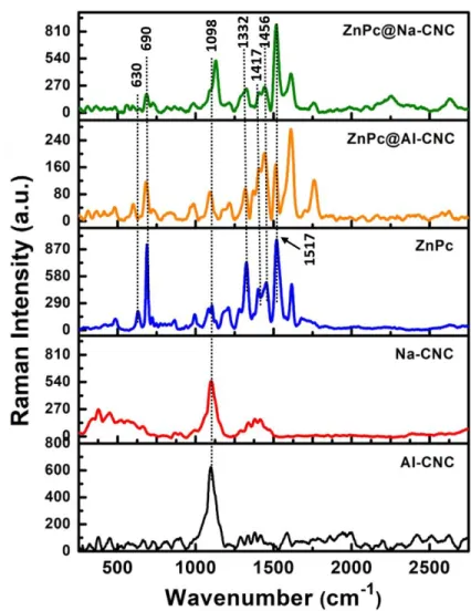
Fig. 3. Raman spectra (532 nm excitation) of (a) AI-CNC (b) Na-CNC (c) ZnPc (d) ZnPc@AI-CNC and (e)
ZnPc@Na-CNC.
Figure 3 shows the Raman spectra of the two bare CNCs, bare pristine ZnPc and the ZnPc conjugated CNCs. Both AI-CNC and Na-CNC exhibit peaks close to 1098 cm-1 due to C–O–C stretching modes in cellulose.44-46 These vibrational modes are also shown by the ZnPc conjugated CNCs as expected. The octacarboxylated ZnPc synthesized in this work exhibits a number of narrow, distinct peaks in its Raman spectrum (Fig. 3). The most prominent peak is observed at a wavenumber of 1517 cm-1, which is attributed to out-of-phase stretching of C-N-C bridges.47-48 In the low frequency region, the most prominent Raman peaks are at 666 cm-1 and 735 cm-1, which are known to correspond
17
to be coupled to the macrocycle) respectively.47-48 Interestingly these two peaks are shifted to lower frequency, 630 & 690 in our ZnPc and the conjugates. This significant down-shifts might have their origin in additional eight -COOH groups attached to the isoindole units of ZnPc. In the high frequency region, intense peaks are also observed at 1332 cm-1, 1417 cm-1 and 1483 cm-1, which correspond to various A1 modes in ZnPc. The aforementioned characteristic vibrations of ZnPc are also observed for
the conjugated ZnPc@AI-CNC and ZnPc@Na-CNC nanoparticles, as seen in Fig 3. However, peaks at 1483 cm-1 are slightly downshifted to 1456 in all the systems containing octacarboxylated ZnPc. The two strong low frequency vibrations (630 and 690 cm-1) are partially attenuated in ZnPc@AI-CNC and strongly suppressed in ZnPc@Na-CNC. Similarly, the A1 modes in ZnPc48 which correspond to in-phase
stretches of Zn-N coupled with indole and benzene ring deformations (1332 cm-1), C-N-C bridges coupled with indole expansions and benzene deformations (1417 cm-1), and C-N-C bridges coupled to indole ring deformations (1483 cm-1), more or less preserve their relative intensities in ZnPc@AI-CNC while being almost totally suppressed in ZnPc@Na-CNC. On the other hand, dominant ZnPc Raman feature at 1517 cm-1 shows opposite behavior in the conjugates, being partially suppressed in ZnPc@AI-CNC and fully expressed in ZnPc@Na-ZnPc@AI-CNC. Vibrations of the macrocycle itself or those coupled to the macrocycle are suppressed in ZnPc@Na-CNC and expressed in ZnPc@AI-CNC, causing us to infer that the zinc phthalocyanines are mostly lying face down on the surface of the Na-CNCs while being rigidly bonded to Na-CNCs through ester linkages. In ZnPc@AI-CNC, more of the metallophthalocyanine rings are likely oriented vertically to the surface (edge-wise linkage to CNC surface).
18
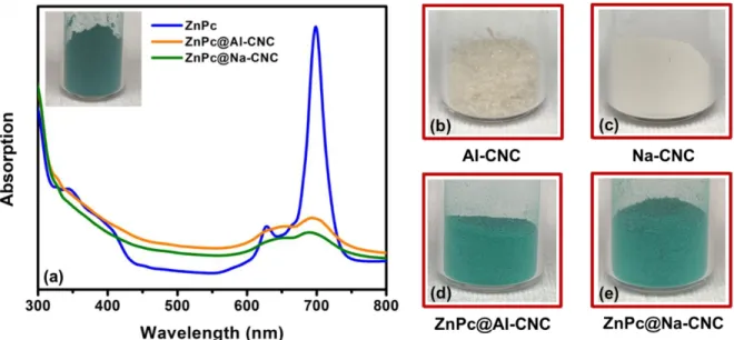
Fig. 4. (a) UV-vis spectra of dispersions of ZnPc and conjugated CNC in DMF. Inset showing a green powder of
octacarboxylated ZnPc; (b), (c), (d) and (e) optical micrographs of bare AI-CNC, bare Na-CNC, ZnPc@AI-CNC and ZnPc@Na-CNC respectively.
Fig. 4 shows the optical absorption of the ZnPc conjugated CNCs in comparison to ZnPc itself. The octacarboxylated ZnPc (blue curve in Fig. 4a) shows the well-known Soret (also known as B) and bands of metallophthalocyanines in the ultraviolet/blue and red spectral regions respectively. The Q-band of ZnPc is a doublet with the lower energy peak (699 nm) corresponding to the S0→S1 electronic
transition while we attribute the higher energy peak (627 nm) to π-stacked columnar aggregates.21 Both ZnPc@AI-CNC and ZnPc@Na-CNC (orange and green curves respectively in Fig. 4a) show the same doublet feature albeit at lower intensity and with more linewidth broadening. Interestingly in the ZnPc conjugated CNCs, the higher energy peak is red-shifted by 20-30 nm, while the lower energy peak is blue-shifted by ~7 nm. We attribute these phenomena to the formation of more disordered aggregates in ZnPc conjugated CNCs. Figs. 4(b)-(e) show the dramatic color change in CNCs following ZnPc conjugation with the resulting conjugated ZnPc@AI-CNC and ZnPc@Na-CNC sharing the bright green color of ZnPc. There is one other critical element that needs to be pointed out. Bare ZnPc has a dramatic drop-off in absorption amplitude immediately following the Soret band and before the Q-band (i.e.
450-19
550 nm). On the other hand, the ZnPc-conjugated CNCs do not show the same sharp drop in absorption and instead continue to robustly absorb light in the 450-550 nm spectral range, which is again due to the presence of larger aggregates of ZnPc.
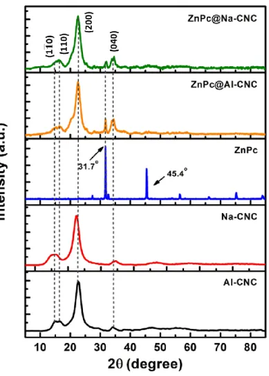
Fig. 5. X-ray diffractograms of bare AI-CNC, bare Na-CNC, bare ZnPc, ZnPc@AI-CNC and ZnPc@Na-CNC.
Fig. 5 shows the powder XRD patterns for the different samples in this study. For the AI-CNCs
as well as the Na-CNCs, reflections from the (1 1 0 ), (110), (200) and (040) planes of cellulose I produce diffraction peaks at 15.2, 16.7, 22.6 and 34.7 respectively.49-51 These peaks are faithfully preserved in the ZnPc conjugated CNCs confirming the presence of the cellulose nanocrystals in the conjugates. The drop-cast ZnPc thin films are polycrystalline with good long-range order as evidenced by their
20
sharp peaks. Two intense peaks are present at 31.7 and 45.4 where peak at 31.7 has the highest intensity followed by peak at 45.4 in the entire spectrum. These are the most prominent peaks found in the octacarboxylated ZnPc reported earlier.52 Both of these peaks are found in ZnPc@AI-CNC and ZnPc@Na-CNC with more intensity in the former.
Fig. 6. Particle size distribution of dilute (~ 0.2 mg ml-1) aqueous dispersions of bare AI-CNC, bare Na-CNC, ZnPc@AI-CNC and ZnPc@Na-CNC, obtained from dynamic light scattering (DLS) measurements.
DLS measurements were performed on the various types of bare and conjugated CNCs, and the resulting data is shown in Fig. 6. Aqueous dispersions of both AI-CNCs and Na-CNCs exhibited bimodal profiles with two distinct sizes, of ~10 nm and ~80 nm. Such bimodal profiles are frequently seen in the DLS spectra of anisotropic nanoparticles, and typically indicate width and length respectively for rod-shaped particles. Following ZnPc conjugation, a large increase in hydrodynamic radius was indicated for both kinds of cellulose nanocrystals. The two characteristic dimensions for ZnPc@AI-CNC were 44nm and 342 nm, and for ZnPc@Na-CNC, they were 38 nm and 164 nm. These results indicate a significant shell of the octacarboxylated CNCs, forming around both kinds of CNCs,
21
likely due to co-facial and herringbone-type π-stacking of ZnPc molecules on top of the first layer of covalently grafted ZnPc. The DLS observations are supported by SEM images of the morphology of thin films of the ZnPc conjugated CNCs (Fig. 7a & 7b). In contrast to the rigid rod like whiskers seen for pristine CNC films,18 finger-like fibrils are observed in Fig. 7(a) and 7(b) for both ZnPc@AI-CNC and ZnPc@Na-CNC thin films respectively. The lateral dimension of these fingers is ~ 20-50 nm and their axial dimension is ~100-200 nm, thus broadly supporting the DLS results. Fig. 7 also shows the high resolution transmission electron microscopy (HRTEM). The calculated d-spacings from these images are well-matched with the observed XRD peaks discussed earlier. The elemental maps are shown in Fig. S3 and Fig. S4 (supplementary information) for ZnPc@AI-CNC and ZnPc@Na-CNC respectively. As expected, all the constituent elements are present in the conjugates with appropriate relative quantities.
22
Fig. 7. FESEM image of (a) ZnPc@AI-CNC and (b) ZnPc@Na-CNC. HRTEM image showing (c) AI-CNC and (d)
Na-CNC surrounded by ZnPc. (e), (f) and (g) HRTEM images showing lattice fringes corresponding to ZnPc XRD peaks.
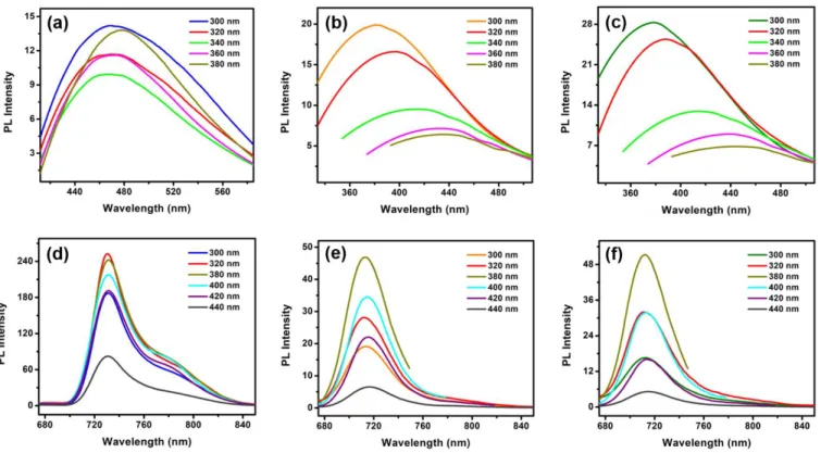
Photoluminescence (PL) spectra were collected from diluted aqueous dispersions of ZnPc and ZnPc conjugated CNCs (Fig. 8) using different excitation wavelengths. Fig. 8 (a)-(c) show the Soret band emission spectra while Fig. 8 (d)-(f) show the Q-band emission spectra. The octacarboxylated ZnPc molecule is brightly fluorescent, and this strong fluorescence is also exhibited by the ZnPc-conjugated CNCs. ZnPc dispersions showed the strongest Q-band emission amplitudes for ultraviolet illumination, specifically 320 and 380 nm excitation (red and dark yellow curves respectively in Fig. 8d). The ZnPc@AI-CNC and ZnPc@Na-CNC dispersions showed the strongest emission amplitudes at 380 nm excitation wavelengths (dark yellow curves in Fig. 8e and 8f). While there is no remarkable broadening of the peaks in both the emission bands, a small blue shift in the Q-band peak (~ 17 nm) and a large blue shift in the Soret band (~ 90 nm) for ZnPc-CNC conjugates compared to pristine ZnPc was observed. This blue shift is an indication of more aggregation in the morphology of porphyrin and phthalocyanine molecules with less amount of flattening.53-54 The conjugation of ZnPc with CNCs also resulted in excitation dependent shift of the Soret band emission peak, where red shift occurs with increasing excitation. Nevertheless, the excitation dependent PL intensity trends in the Q band for the conjugates are almost similar to unconjugated ZnPc. This implies that the ZnPc molecules in the conjugates closely resemble that of bare ZnPc, which is known to form discotic columnar aggregates with co-facial π-stacking.
23
Fig. 8. (a)-(c) Soret band emission spectra of ZnPc, ZnPc@AI-CNC and ZnPc@Na-CNC respectively; (d)-(f) Q-band
emission spectra of ZnPc, ZnPc@AI-CNC and ZnPc@Na-CNC respectively. All the data were collected in DMF for different excitation wavelengths.
Scanning Kelvin probe force microscopy (KPFM) in the dark, and under illumination by LEDs of different wavelengths, was used to obtain insight into the surface potential and photo-induced charge separation in the samples under study. In the dark, the surface potential of the ZnPc as well as the ZnPc conjugated CNC samples is ~ 40 mV (blue, orange and olive in Fig. 9a, 9b and 9c for ZnPc, ZnPc@AI-CNC and ZnPc@Na-ZnPc@AI-CNC respectively) and this uniformity in value is indicative of the ZnPc molecules terminating the surface and determining the charge on the surface. Illumination of pristine ZnPc flakes by 635 nm photons results in a 17 mV shift in surface potential (violet curve in Fig. 9a). The lowest unoccupied molecular orbital (LUMO) of ZnPc is at 3.78 eV below the vacuum level, which facilitates dissociation of the photogenerated exciton in ZnPc and subsequent electron injection into the conduction band of the F-doped SnO2 substrate, which is located at 4.6 eV below the vacuum level. The loss of
24
photogenerated electrons to FTO results in a slight positive charge on the ZnPc surface and generates a positive shift in the surface potential. The high carrier density in FTO ensures rapid recombination of the photogenerated hole in ZnPc with electrons in FTO at the FTO-ZnPc interface due to which the magnitude of the generated photovoltage (17 mV) is rather small. Under constant illumination, a steady state condition is reached wherein the rate of injection of photogenerated electrons into FTO is exactly balanced by back-electron transfer from FTO (interfacial recombination). For 520 nm illumination (cyan curve in Fig. 9a), a smaller surface potential of shift of ~ 9 mV is observed. This is exactly as expected since the absorption coefficient of ZnPc at 520 nm is lower than at 635 nm. In Fig. 9b as well as in Fig. 9c, we observe a negative shift in surface potential upon illumination by 520 nm and 635 nm photons. While the magnitude of this shift is a mere 3-5 mV for ZnPc@AI-CNC (cyan and violet curves in Fig. 9b), ZnPc@Na-CNC exhibit a more substantial shift of 12-21 mV following illumination (cyan and violet curves in Fig. 9b). The opposite direction of the surface potential shift in comparison to ZnPc indicates the ZnPc-CNC interface to now be the driver of charge separation with the ZnPc surface acquiring a slight negative charge following illumination by 520 nm and 635 nm photons. This is because band energetics do not allow the photogenerated hole in ZnPc to be injected into FTO. Therefore, the ZnPc has to be losing some photogenerated holes to the cellulose nanocrystals. Such a charge separation can be rationalized on the basis of the large negative charge on the surface of the CNCs, which provides a driving force for hole transfer to the CNCs. If the structure and morphology of ZnPc-CNC conjugates can be optimized to increase the magnitude of the generated photovoltage to > 0.3 V, a variety of applications in photodetection and photocatalysis open up for CNCs. For 450 nm illumination, all the studied samples (green curves in Fig. 9) exhibit a broad dispersion in the photovoltages that develop at different points on the sample. This suggests that charge separation is governed by local effects and processes such as defects and trap states rather than a clear flow of
25
photogenerated charge from one species to another. It is worthwhile to note that 450 nm illumination generates a significant positive surface potential shift of ~190 mV in bare Na-CNCs on FTO, which is likely due to Urbach tail excitation of FTO followed by hole transfer to the negatively charged Na-CNCs.
Fig. 9. KPFM and Photo-KPFM data collected from discontinuous flakes drop-cast from diluted dispersions (in DMF)
of (a) ZnPc (b) ZnPc@AI-CNC (c) ZnPc@Na-CNC and (d) Na-CNCs for different excitation wavelengths.
X-ray photoelectron spectroscopy (XPS) was used for the determination of materials surface/subsurface chemical composition (~10 nm), binding energy (BE) of elements and their oxidation states. The XPS survey scan of ZnPc for elemental analysis displayed all the core level (Zn2p, C1s, N1s and O1s) and sub-core-level (OKLL, ZnLLM) peaks of constituting elements in the ZnPc structure (Fig. S5, supplementary information). Similarly, XPS survey scan of CNCs also shows all the peaks of
26
composing elements (AI-CNC: C1s, O1s and S2p; Na-CNC: C1s, O1s, S2p and Na1s) (Fig. S5, supplementary information). Acid hydrolysis of cellulose slurry using concentrated sulfuric acid was the source of sulfur in CNCs while sodium was introduced into sodiated CNCs (Na-CNC) during NaOH assisted neutralization step. No signature peak of constituting elements of ZnPc (Zn2p and N1s) was observed in ZnPc functionalized CNCs (ZnPc@AI-CNC and ZnPc@Na-CNC) which might be due to small loading (10% w/w) and masking of ZnPc signals by major components CNCs signal.
Fig. 10. Core-level HR-XPS spectra of (a) ZnPc in C1s region (b) ZnPc in O1s region, (c) ZnPc, ZnPc@Na-CNC and
ZnPc@Na-CNC in N1s region, (c) ZnPc, ZnPc@Na-CNC and ZnPc@Na-CNC in Zn2p region.
The deconvoluted core-level HR-XPS spectra of ZnPc in C1s region shows three peak components centered at BE ≈ 284.1, 285.3 and 288.2 eV. The XPS peak at 284.1 and 285.3 eV was
27
assigned to sp2 carbons of the benzene ring (Cbenzene) and sp2 carbons of pyrrole rings (Cpyrrole) in
isoindole system (Fig. 10a). As expected, two carbons in each pyrrole system directly linked to electronegative nitrogen (pyrrolic and ring N’s) should be observed at high BE value in XPS spectra. The calculated ratio of the percentage contribution of sp2 carbons in benzene ring and sp2 carbons of pyrrole rings (Cbenzene/Cpyrrole) was found to be ~2.70/1.00 that was close to the theoretically calculated
ratio (3.00/1.00), confirms well-constituted isoindole ring system of phthalocyanines. Further, XPS peak component at relatively higher BE value (288.2 eV) was corroborated due to carboxylic acid group (-COOH) decorated on the periphery of phthalocyanine ring systems. The calculated ratio of ring carbons (Cbenzene/Cpyrrole) and peripheral -COOH carbons were found to be 3.91/1.00 exactly matching with
theoretical value (4.00/1.00) confirms successful synthesis of eight -COOH functionalized ZnPc.
The HR-XPS spectra of ZnPc in N1s region can be resolved into two peak components located at 397.9 and 399.7 eV attributed to ring nitrogen’s (Nring) connecting isoindole units and pyrrolic nitrogen
(Npyrrolic) nitrogen in isoindoles moieties respectively (Fig. 10c).55-58 The contribution ratio of ring and
pyrrolic nitrogen’s (Nring/Npyrrolic) was calculated to be ~1.02/1.00 again matched with theoretical value
for phthalocyanines network (1.00/1.00). Additionally, two peak components at 530.9 and 532.4 eV in O1s region of ZnPc were appeared due -OH and C=O oxygens of peripheral -COOH in ZnPc(COOH)8
(Fig. 10b).56The high-resolution Zn2p spectra of ZnPc show two well-separated chemically shifted peak components (Zn2p3/2 and Zn2p1/2) at 1020.9 and 1044.1 eV due to spin orbital coupling in Zn2+ validates
28
Fig. 11. HR-XPS core level spectra of AI-CNC, Na-CNC, ZnPc@AI-CNC and ZnPc@Na-CNC in (a) C1s region (b)
O1s region (c) S2p region.
The deconvoluted HR-XPS spectra of AI-CNC and Na-CNC in C1s region shows four peak components positioned at 284.8, 286.3, 287.5 and 288.2 eV were assigned to C-H/C-C, C-OH/C-O-C, C=O and O-C=O carbons of D-glucose units linked together with β 1-4 glycosidic linkage in polymeric cellulose (Figure 11a).61-63After chemical functionalization of CNCs (AI-CNC and Na-CNC) with ZnPc
via ester linkage (-COO-), the peak position/intensity of C1s peak in ZnPc@AI-CNC and
ZnPc@Na-CNC remains almost same to bare ZnPc@Na-CNCs demonstrating intact chemical framework of ZnPc@Na-CNCs in ZnPc/CNC composites (Fig. 11a). For sodiated CNCs and ZnPc@Na-CNC strong XPS peak at 1071.8 eV due to Na1s was observed confirms the presence of sodium in Na+ phase pure state (Fig. S6). The O1s HR-XPS of CNCs reveals three peaks at ≈BE 531.7, 532.6 and 533.5 eV corroborated to C=O, O-C=O and -OH oxygens respectively (Fig. 11b).64 The peak positions remain identical after the functionalization of ZnPc on CNCs demonstrating a fractional utilization -OH groups in ester bond
29
formations (Fig. 11b). The S2p high-resolution XPS of pristine and ZnPc modified CNCs shows two deconvoluted peaks at 168.7 and 169.8 eV due to S2p3/2 and S2p1/2 components signify that sulfur was
present as sulfate (-SO4—) (Fig. 11c). Interestingly, XRD, PL, UV-Vis and Raman clearly show the
presence of ZnPc on CNCs however signature peaks of ZnPc in N1s and Zn2p region of ZnPc@AI-CNC and ZnPc@Na-ZnPc@AI-CNC were missing. The absence of these peaks suggests low loading of ZnPc on CNCs surface (10% w/w) in comparison to bulk materials, resulted in most of the signals being dominated by CNCs.
4.2 Photoluminescence quenching test
The laboratory synthesized pristine octacarboxylated ZnPc and the ZnPc conjugates with CNCs were tested for sensing performance through observation of photoluminescence quenching using nitrobenzene as a fluorescence quencher. Energy transfer occurs between the fluorophore ZnPc (and the conjugates with AI-CNC and Na-CNC) and nitrobenzene, that results in fluorescence quenching of the former. We have studied this PL quenching experiments in the two regimes, namely low Q and high Q regimes, where they correspond to low and high concentrations of the quencher molecule. The excitation wavelengths in this experiment were 320, 340, 360 and 380 nm. Fig. 12 (a), (b) and (c) show the gradual decrease in photoluminescence of ZnPc, ZnPc@AI-CNC and ZnPc@Na-CNC respectively in the low Q regime, with increasing concentration of nitrobenzene at 320 nm excitation, where NB1 to NB7 represents highest to lowest concentrations of nitrobenzene used in this test. Fig. 12d shows the PL intensity ratio (I0/I) of pristine fluorophores ZnPc, ZnPc@AI-CNC and ZnPc@Na-CNC (I0) and
fluorophores with quencher (I) vs. concentration of the quencher (Q). It is evident that at this low Q, pristine ZnPc and ZnPc@AI-CNC follow Stern-Volmer kinetics that is consistent with diffusion controlled bimolecular reactions.65 It is interesting to note from Fig. 12d that ZnPc@Na-CNC shows deviation from Stern-Volmer condition, as I0/I vs. Q plot is not a straight line but an upward bending
30
quadratic function. Similar behavior was found for other excitations as well, although quenching of PL decreased significantly with increasing excitation wavelength. Fig. S7 (a), (b) and (c) show the gradual decrease in photoluminescence of ZnPc, ZnPc@AI-CNC and ZnPc@Na-CNC respectively in the high Q regime, with increasing concentration of nitrobenzene at 380 nm excitation, where NB1 to NB7 represents highest to lowest concentrations of nitrobenzene. In the high Q regime all three systems showed the upward bending nonlinear curves as a sign of deviation from Stern-Volmer kinetics (Fig. S7d). Excitation wavelength dependent PL quenching (similar to low Q regime) phenomenon was also observed in the high Q regime. The upward bending positive curvatures observed in these plots (Fig. 12d & Fig. S7d) give implications for binding of the quencher molecules with fluorophores that results in something termed as "sphere of action of the excited molecule".66 In this picture (model), a quencher is capable of quenching even without binding.66 It is reasonable to assume that at high Q regime, there is an excess of quencher molecules, and diffusion controlled mechanism, which is a prerequisite to Stern-Volmer kinetics is longer operative. A qualitative analysis regarding the type of PL quenching can be made by the observation of UV-Vis spectra of the fluorophores in presence of the quencher molecule. Static quenching results in more perturbations in the UV-Vis spectra, whereas in dynamic quenching case, this change is negligible.67 From Fig. S8, it is evident that pristine ZnPc shows increased absorbance in presence of nitrobenzene, in both the low Q and high Q regimes, while the conjugates do not show this trend. This observation is supportive of static quenching dynamics in pristine ZnPc, specifically in the low Q regime, as pure static or dynamic quenching mechanism is manifested in linear relationship in Stern-Volmer plot.68 However, in the low Q regime, ZnPc@Na-CNC still showed this nonlinear behavior, where I0/I vs. Q plot is bending upward. Generally an upward bending curve
represents combined quenching.68 Therefore, in summary we conclude that in pristine ZnPc, more static quenching occurs, particularly in the low Q regime. In case of ZnPc@AI-CNC, dynamic quenching
31
occurs in the low Q regime and a combined mechanism is present in the high Q regime. The conjugate ZnPc@Na-CNC showed behavior that supports combined quenching in both regimes. Fig. 12 and Fig. S7 also indicate that despite possible different quenching types in the three fluorophore systems, one common trend is observed for the comparative quenching efficiency, that is in the order of ZnPc@Na-CNC > ZnPc@AI-ZnPc@Na-CNC > ZnPc. This order remains unchanged in both low and high Q regimes at all excitation wavelengths. It is to be noted that data have presented at 320 nm and 380 nm excitation wavelengths only for the low and high Q regimes respectively only. Similar qualitative results were found at other excitations as well, although PL quenching reduced significantly with increasing excitations. Hence, the ZnPc conjugated CNCs have immense potential for sensing applications.
32
Fig. 12. Photoluminescence spectral changes of (a) ZnPc, (b) ZnPc@AI-CNC and (c) ZnPc@Na-CNC on addition of
different concentrations of nitrobenzene in DMF. (d) PL intensity ratio of pristine fluorophores (ZnPc, ZnPc@AI-CNC and ZnPc@Na-CNC) and fluorophores with quencher (nitrobenzene) vs. concentration of quencher. The plots for ZnPc and ZnPc@AI-CNC are following Stern-Volmer kinetics, while the plot for ZnPc@Na-CNC showing positive deviation from Stern-Volmer condition. In all these samples nitrobenzene concentration was kept low.
4.3 DFT results and analysis
Raman spectroscopy implied that, while both horizontal and vertical orientations of the metallophthalocyanine rings on the CNC surfaces are possible, there is a morphological difference between ZnPc@ AI-CNC and ZnPc@Na-CNC. The former prefers the vertical configuration while the
33
later prefers the horizontal orientation. However, since both morphologies are possible in both systems as evident from HRTEM images where same d-spacings were found on surfaces of both the conjugates, we have chosen to study the both scenarios in both systems. As mentioned before, at the first stage of our calculations, cellulose type I (β phase) nanofibrils were taken in a large number to optimize the systems using molecular dynamics simulation approach (Fig. S1, supplementary information). The two
representative hydrophilic and hydrophobic planes, (1 1 0 ) and (200) respectively (Fig. S2, supplementary information), were taken from the large MD optimized systems for the subsequent DFT calculations. These two hydrophilic and hydrophobic planes were kept frozen as the remaining background planes are missing, which would make this top layer almost geometrically intact. However, we relaxed the O atom of CNC surface (from -OH) involved in the covalent bond formation, including few more neighboring atoms of this O atom of the CNC surface plane. ZnPc molecules were attached to these two planes for both of the CNCs in both horizontal and vertical geometries. The entire ZnPc molecule and the surface -SO3 group of CNC, which is a byproduct of H2SO4 hydrolysis,69 are fully
relaxed in the geometry optimization step of the calculation.
The projected density of states (PDOS), obtained by projecting the total wavefunctions onto the orthogonalized atomic wavefunctions, was used to monitor the stability of the conjugated systems. PDOS of the participating atoms (C atom from ZnPc and O atom form CNC surface) in covalent bond formation,70 was analysed to study the robustness of the conjugation between ZnPc and CNCs. The calculated energy positions of the electronic states were perfectly matched for the two atoms involved in covalent bond for the systems under study [Fig. 13 (a, b) 14 (a, b), S9 (a, c) and S10 (a, c)]. However, despite this absolute matching in the energy positions of the states in the occupied and unoccupied regions near the Fermi level, there is a distinction between number of states for the C and O atoms. The PDOS of the O atoms showed higher number of states in the occupied region compared to C atoms,
34
while C atoms showed higher number of states in the unoccupied regions compared to O atoms [Fig. 13 (a, b) 14 (a, b), S9 (a, c) and S10 (a, c)]. This observation can be explained from the electron density difference plots. The negative and positive isosurfaces are shown in ochre and lime colors [Fig. 13 (c, d) 14 (c, d), S9 (b, d) and S10 (b, d)] represent electron depletion and accumulation regions respectively. The values of the isosurfaces were taken as 0.015 eV Å-3.From all these plots it is evident that covalent bond-forming C and O atoms are surrounded by charge depletion and accumulation regions respectively. This is well supported with the observed differences in the number of states in the PDOS.
Fig. 13. Projected density of states (PDOS) of participating atoms in covalent bond formation between ZnPc and
AI-CNC, where metallophthalocyanine rings are likely to orient vertically to the CNC surface; C (ZnPc) and O (AI-CNC)
on the (a) hydrophilic plane (1 1 0 ), (b) hydrophobic plane (200) of AI-CNC. Electron density difference isosurfaces for ZnPc@AI-CNC on (c) (1 1 0 ) plane and (d) (200) plane. The ochre and lime colored surfaces represent charge
35
depletion and accumulation regions respectively. The isosurface value is set to 0.015 eV Å-3. The colors for C, O, H, S, N and Zn atoms are gray, red, white, yellow, blue and cyan respectively.
Fig. 14. Projected density of states (PDOS) of participating atoms in covalent bond formation between ZnPc and
Na-CNC, where metallophthalocyanine rings are likely to orient vertically to the CNC surface; C (ZnPc) and O (Na-CNC)
on the (a) hydrophilic plane (1 1 0 ), (b) hydrophobic plane (200) of Na-CNC. Electron density difference isosurfaces for ZnPc@Na-CNC on (c) (1 1 0 ) plane and (d) (200) plane. The ochre and lime colored surfaces represent charge
depletion and accumulation regions respectively. The isosurface value is set to 0.015 eV Å-3. The colors for C, O, H, S, Na, N and Zn atoms are gray, red, white, yellow, green, blue and cyan respectively.
Fig. S12 (a) shows the highest occupied molecular orbitals (HOMO) and lowest unoccupied molecular orbitals (LUMO) of bare ZnPc molecule. The HOMO and LUMO are closely spaced on the metallophthalocyanine ring. On the contrary, these molecular orbitals are well separated in the
36
conjugates (Fig. 15 and Fig. S11). In both configurations, where metallophthalocyanine rings are perpendicular (Fig. 15) and horizontal (Fig. S11) to the CNC surface, HOMO is mostly lying on CNC surface and LUMO is staying in ZnPc. It is to be noted that, when metallophthalocyanine rings are standing at the edge of hydrophilic and hydrophobic surfaces (Fig. S12b), the HOMO-LUMO spatial separation was not found, rather these orbitals resemble that of the pristine ZnPc (Fig. S12a). This spatial separation of HOMO and LUMO in the conjugates facilitates exciton dissociation. Thus, upon illumination of light, ZnPc surface is likely to accumulate electrons and CNC becomes positively charged. This is exactly what we saw in the KPFM analysis discussed earlier, where larger change was observed in the surface potential for the ZnPc-CNC conjugates compared to the pristine ZnPc upon illumination of light.
37
Fig. 15. DFT calculated spatial distributions of molecular orbitals, where metallophthalocyanine rings are likely to
orient vertically to the CNC surface, for (a) hydrophilic plane (1 1 0 ) and (b) hydrophobic plane (200) of ZnPc@AI-CNC; (c) hydrophilic plane (1 1 0 ) and (d) hydrophobic plane (200) of ZnPc@Na-CNC. HOMO and LUMO are represented by orange and purple lobes respectively. The colors for C, O, H, S, Na, N and Zn atoms are gray, red, white, yellow, green, blue and cyan respectively.
5. Conclusions
Brightly fluorescent cellulose nanocrystal containing nanoparticles were synthesized by covalently grafting octacarboxylated zinc phthalocyanine molecules on to the surface of AI-CNCs and Na-CNCs. The conjugated fluorescent nanoparticles were found to have a core-shell morphology with a CNC core and a relatively thick shell of aggregated ZnPc molecules. Raman, UV-Vis and PL spectra provided some insights into the nature of the aggregates, which were slightly different on AI-CNCs and
Na-38
CNCs. The ZnPc conjugated CNCs exhibit emission maxima in the near infrared spectral region at ~ 713 nm, which renders them interesting for biomedical applications such as imaging and contrast agents, fluorescent drug delivery capsules, photodynamic therapy, etc. Scanning Kelvin probe measurements of the surface potential before and after illumination indicated photogenerated charge separation in the ZnPc conjugated CNCs. For ZnPc@Na-CNCs, an appreciable surface potential shift as high as 20 mV was observed following illumination by red photons. The ZnPc-CNC conjugates showed promising results in the photoluminescence test experiments. Theoretical calculations involving density functional theory showed stable covalent attachment of the ZnPc and CNCs. The larger change in the surface potential measurements using KPFM was supported by molecular orbital localization revealed from these calculations.
Acknowledgements
This work was made possible through direct and indirect funding support from National Research Council Canada (NRC), NSERC, AITF, FP Innovations, CFI, CMC Microsystems and Future Energy Systems. The cellulose nanocrystal samples were provided by InnoTech Alberta and FP Innovations. Special thanks to Dr. Wadood Hamad for constructive discussions. The University of Alberta nanoFAB staff member Anqiang He is acknowledged for his help in collecting HRTEM/EDX data. National Research Council staff member Paul Concepcion and Zhimin Yan are acknowledged for collecting FESEM and NMR data respectively.
References
1. Song, Q.; Winter, W. T.; Bujanovic, B. M.; Amidon, T. E., Nanofibrillated Cellulose (NFC): A High-Value Co-Product that Improves the Economics of Cellulosic Ethanol Co-Production. Energies 2014, 7 (2), 607-618.
2. Trache, D.; Hussin, M. H.; Haafiz, M. K. M.; Thakur, V. K., Recent progress in cellulose nanocrystals: sources and production. Nanoscale 2017, 9 (5), 1763-1786.
3. Tang, J.; Sisler, J.; Grishkewich, N.; Tam, K. C., Functionalization of cellulose nanocrystals for advanced applications. Journal of Colloid and Interface Science 2017, 494, 397-409.
39
4. Akhlaghi, S. P.; Berry, R. M.; Tam, K. C., Modified Cellulose Nanocrystal for Vitamin C Delivery. AAPS
PharmSciTech 2015, 16 (2), 306-314.
5. Golmohammadi, H.; Morales-Narváez, E.; Naghdi, T.; Merkoçi, A., Nanocellulose in Sensing and Biosensing. Chem. Mater. 2017, 29 (13), 5426-5446.
6. Chowdhury, F. I.; Dick, C.; Meng, L.; Mahpeykar, S. M.; Ahvazi, B.; Wang, X., Cellulose nanocrystals as host matrix and waveguide materials for recyclable luminescent solar concentrators. RSC Advances 2017, 7 (51), 32436-32441.
7. Giese, M.; Spengler, M., Cellulose nanocrystals in nanoarchitectonics – towards photonic functional materials. Molecular Systems Design & Engineering 2019, 4 (1), 29-48.
8. Csoka, L.; Hoeger, I. C.; Rojas, O. J.; Peszlen, I.; Pawlak, J. J.; Peralta, P. N., Piezoelectric Effect of Cellulose Nanocrystals Thin Films. ACS Macro Letters 2012, 1 (7), 867-870.
9. Xu, S.; Girouard, N.; Schueneman, G.; Shofner, M. L.; Meredith, J. C., Mechanical and thermal properties of waterborne epoxy composites containing cellulose nanocrystals. Polymer 2013, 54 (24), 6589-6598.
10. Abraham, E.; Kam, D.; Nevo, Y.; Slattegard, R.; Rivkin, A.; Lapidot, S.; Shoseyov, O., Highly Modified Cellulose Nanocrystals and Formation of Epoxy-Nanocrystalline Cellulose (CNC) Nanocomposites. ACS Applied
Materials & Interfaces 2016, 8 (41), 28086-28095.
11. Pei, A.; Malho, J.-M.; Ruokolainen, J.; Zhou, Q.; Berglund, L. A., Strong Nanocomposite Reinforcement Effects in Polyurethane Elastomer with Low Volume Fraction of Cellulose Nanocrystals. Macromolecules 2011,
44 (11), 4422-4427.
12. Cao, Y.; Zavaterri, P.; Youngblood, J.; Moon, R.; Weiss, J., The influence of cellulose nanocrystal additions on the performance of cement paste. Cement and Concrete Composites 2015, 56, 73-83.
13. Fan, S.; Dan, L.; Meng, L.; Zheng, W.; Elias, A.; Wang, X., Improved response time of flexible microelectromechanical sensors employing eco-friendly nanomaterials. Nanoscale 2017, 9 (43), 16915-16921. 14. Kelly, J. A.; Shukaliak, A. M.; Cheung, C. C. Y.; Shopsowitz, K. E.; Hamad, W. Y.; MacLachlan, M. J., Responsive Photonic Hydrogels Based on Nanocrystalline Cellulose. Angewandte Chemie International Edition 2013, 52 (34), 8912-8916.
15. Shojaeiarani, J.; Bajwa, D.; Shirzadifar, A., A review on cellulose nanocrystals as promising biocompounds for the synthesis of nanocomposite hydrogels. Carbohydrate Polymers 2019, 216, 247-259.
16. Du, H.; Liu, W.; Zhang, M.; Si, C.; Zhang, X.; Li, B., Cellulose nanocrystals and cellulose nanofibrils based hydrogels for biomedical applications. Carbohydrate Polymers 2019, 209, 130-144.
17. Wang, D., A critical review of cellulose-based nanomaterials for water purification in industrial processes. Cellulose 2019, 26 (2), 687-701.
18. Alam, K. M.; Kar, P.; Thakur, U. K.; Kisslinger, R.; Mahdi, N.; Mohammadpour, A.; Baheti, P. A.; Kumar, P.; Shankar, K., Remarkable self-organization and unusual conductivity behavior in cellulose nanocrystal-PEDOT: PSS nanocomposites. Journal of Materials Science: Materials in Electronics 2019, 30 (2), 1390-1399.
19. Ferreira, F. V.; Dufresne, A.; Pinheiro, I. F.; Souza, D. H. S.; Gouveia, R. F.; Mei, L. H. I.; Lona, L. M. F., How do cellulose nanocrystals affect the overall properties of biodegradable polymer nanocomposites: A comprehensive review. European Polymer Journal 2018, 108, 274-285.
20. Menezes-Silva, R.; de Oliveira, B. M. B.; Fernandes, P. H. M.; Shimohara, L. Y.; Pereira, F. V.; Borges, A. F. S.; Buzalaf, M. A. R.; Pascotto, R. C.; Sidhu, S. K.; de Lima Navarro, M. F., Effects of the reinforced cellulose nanocrystals on glass-ionomer cements. Dental Materials 2019, 35 (4), 564-573.
21. Ogunsipe, A.; Durmuş, M.; Atilla, D.; Gürek, A. G.; Ahsen, V.; Nyokong, T., Synthesis, photophysical and photochemical studies on long chain zinc phthalocyanine derivatives. Synthetic Metals 2008, 158 (21-24), 839-847.
22. Fernández, D. A. A., J.; Dicelio, L. E., Photophysical and aggregation studies of t‐butyl‐substituted Zn phthalocyanines. Photochemistry and photobiology 1996, 63 (6), 784-792.
23. Shankar, K.; Feng, X.; Grimes, C. A., Enhanced Harvesting of Red Photons in Nanowire Solar Cells: Evidence of Resonance Energy Transfer. ACS Nano 2009, 3 (4), 788-794.