Publisher’s version / Version de l'éditeur:
Journal of Structural Engineering, 25, July 2, pp. 95-102, 1998-07-01
READ THESE TERMS AND CONDITIONS CAREFULLY BEFORE USING THIS WEBSITE.
https://nrc-publications.canada.ca/eng/copyright
Vous avez des questions? Nous pouvons vous aider. Pour communiquer directement avec un auteur, consultez la première page de la revue dans laquelle son article a été publié afin de trouver ses coordonnées. Si vous n’arrivez pas à les repérer, communiquez avec nous à [email protected].
Questions? Contact the NRC Publications Archive team at
[email protected]. If you wish to email the authors directly, please see the first page of the publication for their contact information.
NRC Publications Archive
Archives des publications du CNRC
This publication could be one of several versions: author’s original, accepted manuscript or the publisher’s version. / La version de cette publication peut être l’une des suivantes : la version prépublication de l’auteur, la version acceptée du manuscrit ou la version de l’éditeur.
Access and use of this website and the material on it are subject to the Terms and Conditions set forth at
Seismic analysis of infilled frames
Kodur, V. K. R.; Erki, M. A.; Quenneville, J. H. P.
https://publications-cnrc.canada.ca/fra/droits
L’accès à ce site Web et l’utilisation de son contenu sont assujettis aux conditions présentées dans le site
LISEZ CES CONDITIONS ATTENTIVEMENT AVANT D’UTILISER CE SITE WEB.
NRC Publications Record / Notice d'Archives des publications de CNRC:
https://nrc-publications.canada.ca/eng/view/object/?id=764eac23-6dad-49e8-b048-8a965bf7aeb2 https://publications-cnrc.canada.ca/fra/voir/objet/?id=764eac23-6dad-49e8-b048-8a965bf7aeb2http://www.nrc-cnrc.gc.ca/irc
Se ism ic a na lysis of infille d fra m e s
N R C C - 4 0 2 8 8
K o d u r , V . R . ; E r k i , M . A . ; Q u e n n e v i l l e , J . H . P .
J u l y 1 9 9 8
A version of this document is published in / Une version de ce document se trouve dans:
Journal of Structural Engineering, 25, (2), July, pp. 95-102, July 01, 1998
The material in this document is covered by the provisions of the Copyright Act, by Canadian laws, policies, regulations and international agreements. Such provisions serve to identify the information source and, in specific instances, to prohibit reproduction of materials without written permission. For more information visit http://laws.justice.gc.ca/en/showtdm/cs/C-42
Les renseignements dans ce document sont protégés par la Loi sur le droit d'auteur, par les lois, les politiques et les règlements du Canada et des accords internationaux. Ces dispositions permettent d'identifier la source de l'information et, dans certains cas, d'interdire la copie de documents sans permission écrite. Pour obtenir de plus amples renseignements : http://lois.justice.gc.ca/fr/showtdm/cs/C-42
Jourmll of Structural Engineering Vol.25 No.2 July 1998 pp.95- 102
Seismic analysis of infilled frames
*
.**
**
V.K.R. Kodur , M.A. Erkl
and J.H.P. Quenneville
No.25-9
A numerical e"ample illustrates the steps associated with the seismie design of masonry infilled trames. The e"ample accounts for the effect of the infill in all the design stages: computing seismic loading, predicting the response and assessing the strength of the inr.Iled frame. Numerical results show that the normal design procedures can account for infills in the seismic design of frames.
I
A popular form of construction consists of orthogonally placed frames and infill walls or panels in the plane of the frames. Frames may be of steel, reinforced concrete, or con-crete encased steel frame construction. Materials for infill panels may be solid or hollow bricks, reinforced or unrein-forced concrete blocks, light-weight concrete, composite material, or reinforced concrete and the infill may be with or without openings. With the panel connected to the frame, the total sy!ltem acts as a single unit. With the panel separated from the frame. the frame system can deform in-dependent of the infill during an earthquake.
Properly designed, the infills can increase the overall strength, lateral resistance, and energy dissipation of the structure. Infills reduce lateral deflections and bending mo-ments in the frame, thereby decreasing the probability of collapse. Hence, accounting for the infills in analysis and design leads to slender frame members, reducing the overall cost of the structural system.
Improperly designed infills can decrease the natural period of the structure and increase the effect of seismic forces leading to overloading of parts of the structure. Un-symmetrically placed infills may induce torsional effects, and partial masonry infills can redirect the formation of ductile plastic hinges away from the desirable location at the ends of the beams to the top of the columns. resulting in dramatic increase in column shears. The frame-infill inter-action may also cause local damage in frame element either near beam-column joints, or at mid-height of columns. The combination of t'rames having low lateral stiffness with stiff but poor quality infills may lead to premature failure and subsequent collapse of intills.
Codes of practice, which do not recognise the effect of infill panels, recommend that the base shear be calculated based on the natural period of frame alone. Besides being un-realistic, such an approach can lead to unsafe designs be-cause frame members receive unintended shear and axial forces. Changes in frame behaviour owing to the presence of infills contributed to structural damage in recent earthquakesl -4
For seismic .loads, the accuracy of the predicted force on the infilled frame depends on the accuracy of the calcu-lated dynamic characteristics of the structure, namely, natural frequencies, vibrational modes, and damping. The New Zealand masonry codeS recognises the effect of infills by requiring that the interaction of all structural and non-structural elements affecting the response of the structure or the performance of non-structural elements be considered in the design. Seismic load considerations largely govern the design provisions in this code, ensuring satisfactory structural performance during major earthquakes. Canadian Standards Association6, in conjunction with the National Building Code of Canada? (NBCC) defines specified loads, load effects and load combinations, which govern the struc-tural design of masonry.
In almost all the Codes due to lack of reliable analyti-cal models describing the behaviour of infilled li-ames8 there is a dearth of information to guide the engineer in the analysis and design of infilled frames. Currently efforts are for developing simple guidelines for the design of rein-forced masonry in all seismic zones9.
METHODS OF ANALYSIS TREATMENT OF INFILLS IN DESIGN
Designers often neglect the structural contribution of infills.
,
**
The designer can use static or dynamic analySIS to design infilled frames subjected to seismic loading. The static
Institute for Research in Construction, National Research Council Canada, Montreal Road, Ottawa, KIAOR6,Canada, Department of Civil Engineering, Royal Military College of Canada, Kingston, Ontario K7KSLO, Canada,
analysis involves the analysis of the frame for the equivalent static loads arising from seismic activity, while the dynamic analysis requires analysis in the time domain. Current codes of practice accept that the equivalent static analysis will be sufficient for the seismic design of general multi-storey structures. This is because the dynamic analysis, though accurate, is quite complex.
Static or dynamic analysis can be classified into three broad categories: elastic, plastic and nonlinear analysis. For most applications, codes of practice recommend the elastic analysis. Four major methods used for elastic analysis are, the stress function method, the equivalent diagonal strut method, the equivalent frame method atid the finite element method. Results from any of these four methods depend on the assumptions made and the idealization of the structure used in the analysis.
Table I lists the different methods available for the analysis of infilled frames, together with salient features. Among these, the stress function method is the least ac-curate requiring a large number of trials, while the finite element method is the most complex requiring considerable
TABLE 1
ANALYTICAL METHODS FOR THE ANALYSIS OF INFILLED FRAMES
Method Salient Features
Stress, Function • The panel and frame elements of infill panel are McthodJR assumed to resist a percentage of the total load
• The load carried by infin and frame is estimated
through an iterative approach
• The analysis canbe carried out using hand calculations; However. the method is approximate. Equivalent • The infill is idealiseda.... diagonal struts, and the Diagonal Strut frame is modelled。Nセ beam or truss elements. methodl9,211 • Frame analysis techniques are used for the
clastic analysis
• The idealization is based on the assumption that there is no bond between frame and infilL Equivalent Frame • Frame-infill composite system is replaced by Methodls.21 an equivalent frame, and equivalent transformed
properties are established ..
• Elastic analysis is carried out using beam elements.
• Idealization is suitable for specifying varying properties or to account for openings Finite Element • Infilled frame system is idealised as panel Method22,23 elements, beam elements, and interface elements.
• Interface conditions can be properly simulated by adjusting the properties of interface elements.
·
The analysis requires the use of a computer and detailed results can be obtained. Plastic Method of • The frame infill system is idealised as either Analysis24.25 integral, or senii-integral or non-integral framedepending on the interface conditions.
• Plastic collapse load corresponding to different possible mechanisms is determined.
Nonlinear • The infilled frame is idealised for analysis by Analysis2li the finite element method and the response of the
system is traced by incrementing the load • Effects of geometric and material nonlinearity canbe accounted for in the analysis, but require considerable skill and effort.
Preliminary De:ri.c Estimate Member S es I
t
1 Eotabllsh ReSllonse Soeettal t
I Estimate DamDinJr Ratio I
I
Ideallse !D.fil1.dLセ・ andI
Determine Pro erties
I
be
omnu edセ。ュゥ・ iiViiaii:iic -"nronertJ.esAnalysis.1
N<
I
I
jHッ、。ャセI
Estimate Seisn:iic Load
I
I
セセLs⦅」ヲZGWヲ Irre arItv ..ウセoNU
YES
Determine Other Loads
I
I
St.atie aョ。ャセ •I
Determine Mem er Forces
I
I
Design lnf1ll andI
Frame HembersI
I
Estimate Strength ofI
Member3 NOセ
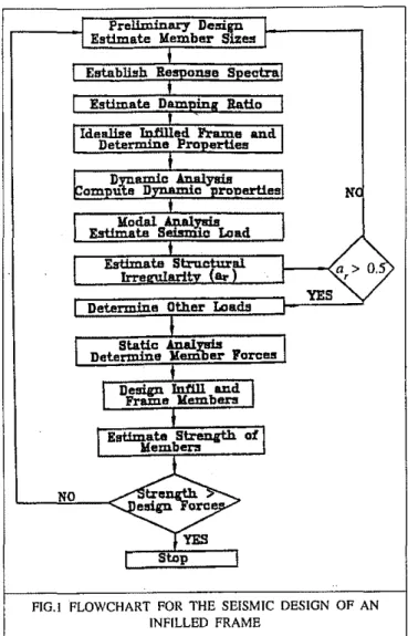
I .top IFIG. I FLOWCHART FOR THE SEISMIC DESIGN OF AN INFILLED FRAME
skills on Ihe part of the designer. In the equivalent diagonal strut method, diagonal struts bracing the frame replace the action of the infills. In the case of the equivalent frame method, a frame having equivalent stiffness replaces the frame-infill composite system.
Researchers have shown that the equivalent diagonal strut and equivalent frame methods give reasonable predic-tions. A recent studylO,t1uses these methods to propose simple guidelines for the seismic analysis and design of infilled frames. A numerical example given herein illustrates the practical application of these design guidelines.
ANALYSIS PROCEDURE
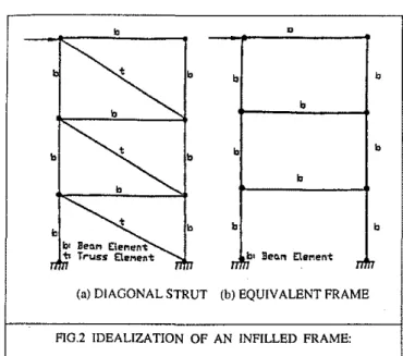
Figure I illustrates the steps associated with the seismic analysis and design of intilled framesII. A diagonal SIrut-frame combinalion (Fig.2a) or an equivalent SIrut-frame system (Fig.2b) represents the infilled frame and beam and truss elements idealise the structure for the elastic analysis. The analysis accounts for the infills in computing the seismic load, in determining the forces in the members, and in determining the strength of the different components of the composite system.
Preliminary design gives an estimate of the member sizes of the composite system. Modal analysis establishes
•
Mainstonethe contact length parameterl4proposes the following relationship to compute(A.)and width(w) t b•
b b•
A. = E i t sin(28) 4 E, Ie h' (I) b t b b b w = 0.175 (W.(),4 d' (2)(a)DIAGONAL STRUT (b) EQUIVALENT FRAME
n
セQ Bea.1'l EtIlMent nIn
b b t br BenM CleMent 'b Truss E1trMen1: b b b bwhereEi is the modulus of elasticity of the infiil material, E,is the modulus of elasticity of frame material Ie is the moment of inertia of column, andt is the thickness of infill. Figure 3(a) shows the variables h, h', d' and 8 and also shows the idealization of an infill panel as an equivalent strut. Knowing the values ofA. and
w;
the designer calcu-lates the other design parameters required for the analysis.FlG.3 DIMENSIONS OF AN IDEALISED INFILLED FRAME
NUMERICAL EXAMPLE
Figure 4 shows the numerical example used herein to il-lustrate the aforementioned analytical procedure for the
seismic analysis and design of an infilled frame of a
three-storey, three-bay reinforced concrete building. The spacing of the frames in the X direction is 8 metres. The brick masonry walls laterally support the frames and at the centre of each wall, there is an opening, 0.8 x 0.8 m.
The numerical examplelO.lI illustrates three cases for
the analysis of the infilled frame. The first one, Case (b) EQvIVALENT PLANE
FRAME MODEL (a)DIAGONAL STRUT MODEL
Equivalent Frame
Figure 3(b) shows an infilled frame idealised as an equivalent frame, for which the modified properties of the frame account for the effect of the infill. Liauwl5proposes
transforming the frame-infill members. into equivalent
sections of frame using the modular ratio of the frame and infill material. Liauw notes that the calculation uses the corner parts of the infill twice to calculate the moment of inertia of the beams and columns of the frame. As expected, this tends to increase the stiffness of the frame, because the corners of the infill stiffen both the beams and columns.
Since the transformed sections of the equivalent' frame
normally consist of deep beams and wide columns, calcula-tion needs to account for the shear strain energy. Using this approach the designer can account for the presence of
open-ings in the infills while calculating the sectional properties of the equivalent frame members.
Diagollal Struts: In this idealization, an equivalent diagonal strut of length,
a,
and width, wd' replaces the infills. The designer checks the adequacy of the designed infilled frame system by checking the strength of the frame members against the induced force due to the loads. These checks include consideration of the cracking and failure modes for both the concrete frames and infills. The design of the frame and infill is satisfactory when the computed strength for anticipated modes of failure exceeds the design forces in these members. The possible modes of failure dueto seismic loads are tension failure of the windward column,
or shear failure of the columns and beamsI3
FlG,2 IDEALIZATJON OF AN INFILLED FRAME: the seismic loading corresponding to an earthquake spectra, and a static analysis yields the member forces and displace-ments. The designer compares these forces with the strength of the infill and frame corresponding to possible modes of failure.
The designer uses dynamic analysis to predict the
seismic loads and obtains the required seismic response
spectra from codes. Beam and truss elements idealise the intilled frame, and a frame analysis gives the computed dynamic properties. A modal analysis procedure uses these dynamic properties to calculate the base shearl2The
desig-ner distributes the maximum base shear as lateral forces in
the different storeys, based on the relative masses of each storey, and later distributes the corresponding lateral force to each column nf the storey.
The designer establishes the total load acting on the infilled frame system, with due consideration to load factors and load combination factors given in codes of practice. Un-symmetrical distribution of the infills leads to additional loads from to",ion. Using all predicted loads, a static
analysis for frame can give an estimate of the member
for-ces. These member forces are then used for the design of the columns, beams, and infills. The designer then estimates the structural irregularity parameter, a,.. for the infilled frame.Ifar is less than 0.5, the designer changes the verti-cal distribution of the intills, and repeats the above steps.
tI ISS he lie in lhe ic It-'m ber hes ,e n n :n
All、ゥュ・ョNセゥョm in m (3) (4)
(5)
+
rt(b-bol (b-b"+
2h) Bhx+
rt(b - b) y = Dynamic PropertiesFigure 5 illustrates the use of the frame analysis program with a two-dimensional idealization to calcultite the dynamic properties of the building. Table 4 summarises the resulting natural frequencies, periods and corresponding modes of vibration. It is seen that the infill significantly reduces the natural period for Case B. The presence of openings, (Case C), results in a slightly higher natural period as compared to that for Case B. As expected. the The distance of the centroid, y, of the composite sec-tion from the outer fibre of the actual beam is:
Moment of inertia, Ib, with respect to the centroida! axis X for the beam member of the equivalent frame is: and C. Figure 3(b) shows the idealised rectangular infilled frame with an opening at the centre, together with its dimensions. The cross-sectional area of the beam of an equivalent frame,Aeq,is:
in which the quantities on the left hand side refer to the actual frame member and the infilI. HenceIbis:
where ris the ratio of the Young's modulus of the infill to that of frame (Ej / E/).
I
=.l
[Bh3+
rt(h _ b )3]+
1
[Bh3+
rt(b - b )b 12 x (/ 4 x ()
I [Bh2
+
rt(b-b )(b-b +2h )]'(b-b +2h )2J_- x " " x II"
" x· 4 Bhx
+
rt(b - b,,)Calculations for the equivalent properties of tilL'
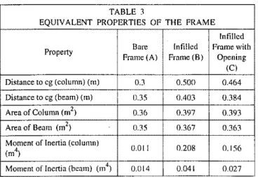
column member proceed similarly. Table 3 summarises the equivalent properties of the column and beam, correspond-ing to the three cases considered in the analysis. The values from Tab!e 3 show that the effect of the infill was to in-crease the moment of inertia of the column by 20 times.
TABLE 3
EQUIVALENT PROPERTIES OF THE FRAME
Infillcd
Property Bure Infilled Frame with
Frame (A) Frame (8) Opening tel Distance to cg (column) (m) 0.3 0.500 0.464
Distance to cg (beam) (m) 0.35 0.403 0.384
Area of Column (m2) 0.36 0.397 0,393
Area of Beam (ml) 0.35 0.367 0.363
Moment of Inertia (column)
0.01 I 0.208 0.156 (m4)
Moment of Inertia (beam) (m4) 0.014 0.041 0027 3.75 kPa 1.5 kPa OAkPa 5.625 kPa 1.00 kPa 2.50 kPa a"
I
,
.
y:
.
1
, • s • u = 412.8 kN = 42080 kg = 15028 Frame tnfill (Brick Property (Reinforced Concrete) Ma.<;onry) Compressive Strength(f,.')(MPa) 20 3Shear Strength (MPa) 0.5
Tensile Strength (MPa) 2.5 0.35
Elastic Modulus (MPa) 200000 2000
Yield Strength of Reinforcement (MPa) 400
Unit Weightkg/m3 2500 2500
W
Total mass Mass density
The gravity loads on the building are: Floors: 150-mm thick slab
Floor finish, ceiling, services Movable partitions, carpets, etc. Tota! dead load on slabs Dead load of masonry walls Live load on all tloors and the roof
The calculation for the loading from the floors and partitions on the beams uses the total dead load on slabs and the weight of walls. The total loading which is taken as the total tloor weight plus that of the tributary walls. is:
Material Properties and Loading
Table 2 summarises the materia! properties used in the analysis. The example uses brick masonry for the infills and reinforced concrete for the columns and beams. Figure 4 gives the beam and column cross-sectional dimensions. The thickness of the slab is 150 mm. The thickness of the masonry infiII is 100mm.
A, considers the contribution of the bare frame without in-tl!l. Cases Band C take into account the effect of infill throughout the frame, and the openings present in the infill respectively.
Properties of an Equivalent Frame
An equivalent frame replaces the infilled frame for Cases B TABLE 2
MATERIAL PROPERTIES OF THE FRAME AND INFILL FIGA FLOOR PLAN AND ELEVATION OF
A THREE STOREY BUILDING
The example assumes that all the load factors and material resistance factors are equalto unity.
s h mg Illy of \ral Ihe
..
..
..
セ v u•
t3..
..
..
w"
..
セ"
"
..
'"
'"
"
••
セ ;n.,
en.
セB @'n"I'
I'
'.
,
,
\FIG.5 IDEALIZATION OF A TWO-DIMENSIONAL FRAME FOR DYNAMIC ANALYSIS
TABLE 4
DYNAMIC CHARACTERISTICS FOR THE FRAME
Property Bare Frame (A) Infilled Frnme (B) Infilled Frame
with Opening(C) Mode Number I 2 3 I 2 3 I 2 3 Nalural fセケ 1.59 5.12 8.84 3.72 14.1 14.9 3.21 12.5 14.8 (Hz) Period 0.627 0.195 0.269 0.071 0.067 0.08 0.D7 (sec) 0.113 0.311 Mode I 0.329 -I.IZ] 2.446 0.234 -1.147 -0.286 0.232 -Ll4 -0.27 Shape 2 0.743 -0.778 -2365 0.636 -1.03 -0214 0.637 -1.07 -0.27 (Col) 3 I I I I I I I I I
natural period in all three cases decreases with higher modes. The mode shapes vary widely indicating that the calculated beha'/iour of an infilled frame depends on the idealization used in the analysis.
Seismic Loading
The design earthquake response spectrum used for this ex-ample is normalised to a peak ground acceleration7 of I g. The infilleo frame is in the seismic zone with a peak ground acceleration of 0.4 g. The damping ratiol6 of the intilled reinforced concrete frame system is 3% for all three Cases. The ordinatesSet'. Sv'and Sa' from first three mode shapes, multiplied by 0.4 give the design values of spectral displacements (Sd), velocities (Sv)' and accelerations (Sa)
corresponding to the first three natural periods. Table 5 lists the values corresponding to three natural modes.
TABLE 5
DESIGN SEISMIC SEPCTRUM VALVES FOR THE FRAME Property Bare Frame (A) Infilted Frame (B) Infilled Frame with
Opening(C) Mode I 2 3 I 2 3 I 2 3 Number Period 0.63 0.195 0.113 0.26910.071 0.067 0.311 0.08 0.D7 (sec) S,,(m) 0.1 0.016 0.008 0.032 00019 0.0018 0.036 0.002 0.002 S,.(m/sec) 0.9 0.56 0.38 0.7 0.156 0.152 0.72 0.16 0.152 S(I(rn'sc<?) 0.9 1.6 1.6 1.6 1.44 1.44 1.6 1.44 1.44
Use of a spreadsheet and the modal analysis proce-dure gives the seismic loading on the building12 Kodur et aJ.10.11 illustrate the calculations of the modal participation. factors, horizontal deflections, equivalent lateral forces and base shear. Table 6 compares the resulting base shears.
The National Building Code7gives the provisions for the base shear due to seismic loading, using a static approach to estimate the base shear. The minimum design base shear is:
(7)
where v is the zonal velocity ratio, S .is seismic response factor, Ijis the seismic importance factor, Fris the
founda-tion factor, and W is the weight of the structure. The seismic response factor is a function of time period
(D
and the velocity.Table 6 presents the maximum probable base shear and the base shears for the three modes for CasesA, B, and C, together with the base shear as per the NBCC7 The second and third modes have little influence on the maxi-mum probable base shear values. The maximaxi-mum probable base shear is significantly higher in Cases Band C, indicat-ing that the presence of infills attracts higher seismic loads. The increased seismic acceleration from the reduced natural period results in higher shear. The base shear trom the code is higher than that obtained from modal analysis for all three cases. The Code formula does not recognise the effect of infill panels and is very conservative when compared with the base shear of the bare frame.
TABLE 6
EQUIVALENT LATERAL FORCES AND BASE SHEARS FOR THE FRAME
Property Bare Frame (A) Infined Frame (8) Infilled Frame with Opening(C) Mode I
I
2I
3 1I
2I
3 1I
2I '
Number Max. Probable 99772 16,507 163206 Base shearBa,<;e shem' 97718/1914516245 16105SI'4.oo/13410 16<JJIlII'5.1.I,o.?
nbcb。Lセ
186000 186000 186000
shear
Note: All unitsinNewtons
The different storeys receive proportional amounts of the maximum probable base shear, with respect to their masses, except for the top floor, which receives 10% of the base shear to account for the influence of higher modes in increasing moments and shear at higher levels.
Table 7 lists the resulting lateral forces, F, at each storey for columns I, 2 and 3, owing to a seismic peak ground acceleration of O.4g, for the three cases. Each storey receives a portion of the base shear calculated in accordance with the Code provisions. Table 7 also gives the resulting lateral forces. Figure 6 shows the variation of lateral forces over the height of tl;1e frame for three cases of analysis
4 1326 85.5 0.004 1388 139.3 0.0008 1382 137.2 0.001
(9)
- e - BareFnune
-<!lo_InflUed Fr:aml! -9-WillwithOpening
Fwcco
=
Asc1.
y=
3080 kN12,---.,---i-rl>---.,----.,----,--;;Ef-/1//
/ / / /
/
/
/" 8 _··.-···f··?·
_ -
_ .,.._ -... .
:g
11 / / , .,.,.... セ iセO ...=
1 / .... 4&
_;;""'::: .
iセi ",;'; /I ,;"f /
oセOZNNO _ _L -_ _.L-_ _- ' -_ _"":_ _-:-:':-:-_---::: 0.000 0.002 0.004 0.006 0.008 0.010 O.OJ:! Defleetlon(In)The crushing strength of the column,Flces' which oc-curs when the stress in the concrete reaches its ultimate capacity, is:
Flees = b d f'c c c
+
(r - I) A._ef,.'s , =8586 kN (10)FIG.7 VARtATION OF STOREY DEFLECTIONS FOR THREE CASES OF FRAME IDEALIZATION
Strength of Column: The cracking of the concrete column
occurs when the stress in the concrete reaches its tensile strength,!,'. The cracking strength of the column, Fweer' is: receive the maximum moments, shears, and axial forces, The forces in the two intermediate columns are higher than those in the two end columns. The top storey deflection in the bare frame is nearly three times higher than that of the infilled frame. This increase in deflection occurs despite the smaller magnitude of applied lateral force at the different storey heights. The deflections increase for Case C, because of the reduction in stiffness from the presence of the open-ings. The resulting column shears in Cases Band Care higher than that in Case A, because of the higher applied lateral forces.
Strength of Frame and Inlill
The strength requirements of the structure are satisfied by checking the strength of the columns and the infills under different cracking and failure modes. In concrete infills, the usual failure modes are tension cracking along the compres-sive diagonal, followed by crushing near one of the loaded corners. In the case of a relatively stiff frame, crushing might occur in the interior region of the infill. For infills constructed with brick masonry. shear failure can occur along the mortar joint to masonry panel. Kodur et al. 1O describe the checks for the strength of the columns and infills under different cracking and failure modes, using em-pirical relationships developed by previous researchers B .t?
Using the tensile load required to cause yielding of the reinforcement, the ultimate collapse load of the column,
FWCC()'is: IlIiIINIle . . Tnnu wllh Opening _ iョュャ・、ヲGョュセ
o
B&reF..ュセ 10 W W セ セ 00 W W セ 100 Storey Shear FDfCC (kN) o o'1=========
Bare Frame fnfilled Frame Infilled Frame
Storey
(A) (B) with Opening NBC
(C) 14966 24526 24481 31000 2 29932 49052 48962 62000 3 54875 89930 89763 93000 A V a .x A V 6 .y A V D . .x Column セ (kN) (kN) (m) (kN) (kN) (m) (kN) (kN) (m) compared to the code values. Table 7 and Fig. 6 show that compared to Case A, the lateral forces at each floor level are higher in Cases Band C, because these cases account for the infill. The lateral forces obtained through the Code are higher than those got from the other three cases.
6 432 57.1 0.01l 448.1 104.3 0.0034 446.6 JOU 0.0046
Note: The displacement is at the top end of the column
5 879 81.7 0.008 916.7 131.7 0.0021 913.4 128.7 0.003
Note:All units in Newtons
Structural Irregularities and Torsional Effects
The structural irregularities, both horizontal and vertical, in this example problem are almost negligible because of the symmetry of the frame. The torsional effects in the present example are not considerable because the calculation uses the actual stiffness of the infilled frame. However, Kodur et al. 10 show how to account for the structural irregularities and torsional effects in the analysis.
Static Analysis
To determine the response of the structure for seismic peak
acceleration using an elastic analysis, the input values are
the static equivalent loads (both lateral and gravity loads). The elastic analysis consists of a frame analysis, with the infilled frame idealised as in Fig.2. Table 8 shows the force and horizontal displacement A, in columns 4,5 and 6. Fig.7 shows the variation of storey deflections for three cases of frame idealization. As expected, the first storey columns
TABLE 8
MEMBER FORCES FROM STATIC ANALYSIS FIG.6 VARIATION OF BASE SHEAR FOR THREE CASES OF
FRAME lDEALIZATJON
TABLE 7
LATERALS FORCE DUE TO SEISMIC ACCELERATION
InflJled Frame with Bare Frame (A) InfiUed Frame (8)
Strength of Infill:The panel ratio(1' :h')of the infill is 2.03, and the value of Ah is equal to 1.895. This section explains how to compute the strength of the infill under different modes of failure, knowing the values of Ah andw.
Smith and Carter13 define the crushing strength of brick-work,Rc' by:
if
m'ht)11 sec(e)Rc
=
2Ah=
1I09kN (II)2. Mitchell, D., "Structural damage due to the 1985 Mexico earthquake"Proc. Fifth Canadian Conference on Earthquake Engg. 1987, Ottawa, A.A. Balkema, Rotterdam, pp.87-111.
3. Mitchell, D., Adams J., Devall, R.H. and Weichert, D., "Lessons from 1985 Mexican Earthquake", Canadian
J.of Civil Engg.,Vo1.l3, 1986, pp.535-557.
4. Stratla, J.L., "Manuai of Seismic Design", Prentice Hall, Book Pub. Co., N.J., 1987.
SUMMARY
The predicted tensile strengthof brickwork, cor-responding to diagonal cracking is:
REFERENCES
1. Minami, T., "Stiffness Deterioration Measured on a Steel Reinforced Concrete Building" Earthquake Engg. and Struct. Dyn.,Vol.15, 1987, pp.697-709. and give design curves based on the following empirical relationship17 to calculate the shear strength of brick work,R,s
R
=
if'
ht)1.85 [I: J.6
[Ahj-D·05F
=
777 kN (12)., S h
/'h'
14. Mainstone, R.J., "Supplementary Note on the Stiffness and Strength of Infilled Frames" Current Paper C.P.
1314, Building Research Station, Watford, UK 1974.
16. Cook, N.J., "The Designer's Guide to Wind Loading of Building Structures, Part I," Building Res. Est., But-terworths, London, 1985.
12. Smith, B.S. and Coull, A., "Tall Building Structures -Analysis and Design", John Wiley & Sons, Toronto, 1991, pp.537.
15. Liauw, T.C., "An Approximate Method of Analysis for Infilled Frames with or without Opening" ,Build. Sci., Vol.7, 1972, pp.233-238.
13. Smith, B.S. and Carter, C., "A Method of Analysis of Infilled Frames", Proc. I. C. Eng., Vol.44, 1969, pp.31-48.
5. NZS4230: Part I, "Code of Practice for the Design of masonry Structures", Standards Association of New Zealand, Wellington, New Zealand, pp.71.
6. CAN3-S304-M84, "Masonry Design for Buildings", Canadian Standards Association, Rexadale, Ontario, Canada, 1990, pp.79.
7. "National Building Code of Canada",Associate Com-mittee on the National Building Code, National Re-search Council of Canada, Ottawa, 1990.
8. Vintzeleou, E. and Tassios, T.P., "Seismic Behaviour and Design and Infilled RC Frames" Int. J. of Earthquake Engg. and Engg. Seismology, Vol. III, No.2, 1989, pp.22-28.
9. Noland, L. James., "Status Report: US Co-ordinated Program for Masonry Building Research",Proc. Fifth North American Masonry Conference,Vol.1, 1990, Ur-bana-Champaign, Illinois, USA, 1990, pp.57-68. 10. Kodur, VKR., Erki, M.A. and Quenneville, J.H.P.,
"Seismic Behaviour and Design of Masonry Infilled Frames",Civil Engg. Research ReportCE 94-1. 1994, Royal Military College of Canada, Kingston, Ontario, 1994.
II. Kodur, V.K.R., Drki, M.A. and Quenneville, J.H.P., "Seismic Design and Analysis of Masonry Infilled Frames". Canadian J. of Civil Engg., No.3, Vol.22, 1995.
(13)
[ l'
J.98
[
l'J.47
R, =
if:
ht) 3.1 h' [Ahj-D.l h' =794 kN From the above analysis, the ultimate strength of a column and the infill are 3080 kN and 777 kN, respectively. Cracking in the column occurs at a load of 1073 kN. The maximum force in the column at the bottom storey is 1326 kN. The results of a static analysis using compatible defor-mations give the force in the diagonal truss member of the infilled frame induced by seismic loading. The force in the truss member is 42.8 kN at the first storey and 178.2 kN at the third storey. Since the strength of the column and the infill exceeds the total load due to seismic and gravity load-ing, the infilled frame satisfies the safety condition. The above procedure can check the adequacy of the design for Case C, while the check for Case A is only the strength of columns against the actual loads.This paper describes an analytical procedure for the seismic design of masonry infilled frames using a numerical example for three cases of frame idealization: bare frame, infilled frame, and infilled frame with openings. There are three stages of the analysis; computing the seismic loading, determining the forces and evaluating the strengths of infill and frame. The seismic load computed from the proposed procedure is smaller than that obtained from the National Building Code7 reflecting the conservative nature of the Code. The normal course of design can account for infills using a frame analysis computer program and spreadsheet software, both of which are generally available in design offices. ,y
I
セイ Ie s-;d Ig Is ur 10 Id n-7 :In de m, of 8) oc-ate 10) (9)17. Govindan, P., Lakshmipathy, M. and Sanathkumar, A.R., "Ductility of Infilled Frames",A.C.l.J.,VoL83,
1986, pp.567-576.
[8. Polyakov, S.V., "On the fnteraction between Masonry Filler Walls and Enclosing Frame when Loaded in the Plane of the Wall", Earthquake Engg Res. Inst., San Francisco, U.S.A., 1960, pp.36-42.
19. Smith, B.S., "Methods for Predicting the Latera[ Stiff-ness and Strength of Multi-storey Infilled Frames" Build. Sci.,VoL2, 1967, pp.247-257.
20. Sobaih, M. and Abdin, M.M.. "Seismic Ana[ysis of Infilled Reinforced Concrete Frames" Compo and Struct..No.3, Vo1.30, 1988, pp.457-257.
21. Liauw, T.C. and LEE. S.W., "On the Behaviour and the Analysis of Mu[ti-storey Infilled Frames Subject to Latera[ Loading"Proc.f.e. Eng..Part 2, VoL63. 1977, pp.64 1-656.
22. Mallick, D. V. and Severn. R.T.. "Dynamic Charac-teristics of Infilled Frames". Proc. f.
e.
Eng ..VoL19,[968, pp.26 1-287.
23. Riddington, J,R, and Smith, B.S.. "Analysi, of Infilled Frames subject to Racking with Design Recommendations", The Struct, Engr" No.6, VoL55. 1977, pp.263-268.
24. Liauw, T.e. and Kwan, K.H .. "New Developments in Research on Inlilled Frames", Proc. oj the Eighth World Con! on Earthquake Engg ..VoI.!V, [984. Pren-tice-Hail Inc., Englewood Cliffs, New Jersey. pp.623-630.
25. Liauw, T.e. and Kwan. K.H.. "UniliedPlastic Analysis for Infilled Frames".ASCEJ. of Struct. Div. ST7,Vol.l[1, 1985,pp.[427-1448.
26. Liauw. T.e. and Kwan, K.H., Nonlinear Analysis of Multi-storey Infilled Frames, Proc. f.