CAUSES AND ANALYSIS OF FAILURES IN IN-SITU
MICROSCOPY OBSERVATION FOR THE
CHARACTERIZATION OF SCALING IN MEMBRANE
DISTILLATION MEMBRANES
by
Pedro Polanco
Submitted to the Department of Mechanical Engineering in partial fulfillment of the requirements for the degree of
Bachelor of Science in Mechanical Engineering at the
MASSACHUSETTS INSTITUTE OF TECHNOLOGY June 2017
0 2017 Massachusetts Institute of Technology. All rights reserved.
Signature
Author ...Certified by.
<S
i
redacted
Pedro Polanco Department of Mechanical Engineering May 22, 2015
gnature redacted
John H. Lienhard V Abdul Latif Jameel Professor of Water
Signature redacted
Thesis SupervisorAccepted by ... ...
Rohit N. Karnik Undergraduate Officer, Department of Mechanical Engineering
ARCHIVES
M USETTS INSTITUTE QF TECHN LOGY
JUL 2
5
Z017
LIBRARIES
CAUSES AND ANALYSIS OF FAILURE IN IN-SITU MICROSCOPY OBSERVATION FOR THE CHARACTERIZATION SCALING IN MEMBRANE DISTILLATION MEMBRANES
by Pedro Polanco
Submitted to the Department of Mechanical Engineering on 5/23/2017 in partial fulfillment of the
requirements for the degree of
Bachelor of Science in Mechanical Engineering
ABSTRACT
In membrane technology at large, fouling limits membrane performance and membrane lifespan. In the case of reverse osmosis membrane distillation (MD) involving fluid mixtures of inorganic elements, inorganic foulants build up on membrane surfaces, and reduce the flux of fluids across a membrane. Inorganic fouling can degrade the quality of water produced by membrane distillation. In order to counteract the effects of membrane fouling, potentially costly procedures like intense chemical cleaning or membrane replacement are necessary. Some theory suggests that, instead of reacting and adhering to membrane surfaces, salts tend to bulk nucleate in solution, and then deposit on high energy surfaces, like metal heat exchangers and hydrophilic reverse osmosis membranes. This is in contrast to the theory that
crystals first deposit on the membrane surface to cause fouling. A solution of Na2SO4. and CaCl, was
pumped across a membrane at 70'C at 2.6 GPM (9.8 LPM) to observe membrane fouling. Using an in-situ camera, fouling on a membrane distillation surface was captured to characterize the nature of MD fouling. Due to failures in heat distribution across the solution and system leaking, no fouling on the membrane surface was observed.
Thesis Supervisor: John H. Lienhard V Title: Abdul Latif Jameel Professor of Water
TABLE OF CONTENTS
A B S T R A C T ... 3
ACKNOW LEDGEM ENTS...5
B IO ... 5 CHAPTER 1. INTRODUCTION:...6 1 .1 M O T IV A TIO N ... 6 1.2 B A C K G R O U N D ... 6 CHAPTER 2. M ETHODOLOGY...8 2.1 EXPERIMENTAL DESIGN...8 2.2 OPERATING CONDIT.IONS... 10 2 .3 C A M E R A S E T U P ... 10
CHAPTER 3. CAUSES AND ANALYSIS OF FAILURES...12
3.1 TROUBLE SHOOTING... 12
3.1.1 Leaking at Low Temperature... 13
3.1.2 Leaking at Low Temperature Revisited...14
3.1.3 System Contamination at High Temperature... 14
3.1.4 Significant Leaking at Threads of Filter Casing... 16
3.1.5 New Barrier for Heater...16
3.1.6 Pressure Drop Due to Hot Feed Flow Interruption... 17
3.1.7 First Experimental Run with Saline Hot Feed... 17
3.1.8 Results of Leaking with Saline Hot Feed...18
3.1.9 Pressure Drop Due to New Filter... 18
3.1.10 Leaking at Low Temperature Revisited... 20
3.1.11 New Barrier for Heater Revisited... 20
3.1.12 Second Experimental Run with Saline Hot Feed... 21
3.1.13 Increasing Salt Concentration of Saline Hot Feed... 21
3.1.14 Salt Buildup on Heater... 22
3 .2 C A M E R A S E T U P ... 2 3 3.3 PERMEATE M ASS VS. TIME...24
C H A PT E R 4. C O N C L U SIO N S...25
C H A P T E R 5. R E FE R E N C E S...26
5 .1 B IB T E X C IT ATIO N ... 2 6
ACKNOWLEDGEMENT S
Thank you to the Rohsenow Kendall Heat Transfer Laboratory, Prof John Lienhard, Jaichander Swaminathan, Tamanna Urmi, and Natasha Balwit for their help and continuous support throughout this process.
Special thanks to David Warsinger for his invaluable contributions. I know I was never the easiest researcher with which to work (81 units or otherwise). Despite all the personal hardships and experimental failures, he guided me through the research and writing process as my most immediate, optimistic, and impactful supporter. I don't know if I would have gotten to fulfill this final graduation requirement without his help. I wish him all the best with his career as a professor and researcher.
Bio
Pedro Polanco is a senior studying mechanical engineering at the Massachusetts Institute of Technology. He is pursuing his passions for assistive technology, people management, and mentorship through coursework, work experience, and extra-curricular involvement. He will start as a full-time associate for Accenture Strategy in September 2017.
CHAPTER
1.
INTRODUCTION
1.1 MOTIVATION
Membrane distillation (MD) is a relatively novel and cost-effective process used to decontaminate water in applications ranging desalination, wastewater treatment and the food industry. MD can be accomplished using waste heat, solar thermal, or geothermal heat sources [1]. MD is a thermally-driven separation process in which only vapor molecules are transferred through a microporous hydrophobic membrane. The driving force in the MD process is the vapor pressure difference induced by the temperature difference across the hydrophobic membrane [2]. MID membrane hydrophobicity and surface quality significantly impact performance in membrane distillation. The polar component of surface energy is the key factor that controls scale formation on MD membrane surfaces, which blocks pores and reduces flux across MD membranes [3,4]. Studies have shown that fouling at high saturation indices can block membrane pores, thereby decreasing the flux of pure water vapor permeate through membrane surfaces, and wetting membrane surfaces. Decreasing flux and wetting membrane surfaces can cause saline hot feed water to contaminate the pure water permeate. High salt concentration in saline hot feeds contributes to scaling, although MD membranes can withstand high saturation indices (SI), or salt concentrations, without fouling. Similar hydrophobic materials as those used for membrane distillation are often used to coat heat exchangers because of their advantageous scaling resistant properties. This enables MD membranes to operate in the removal of brine from other desalination systems, or to concentrate industrial waters. This study investigates the importance of the particulate formation method in scaling conditions.
1.2 BACKGROUND
Generally speaking, scaling considers large crystal growth on membrane surfaces, while particulate fouling considers small crystal deposits on membrane surfaces. Characterizing particulate fouling can help establish limiting supersaturation conditions that can allow the membrane to operate
without fouling. Literature around fouling lacks a systematic approach to determine which conditions cause fouling at the membrane surface or in the bulk solution.
Inorganic fouling happens in two steps. First, crystals from the solution nucleate. Next, crystal grows, which happens spontaneously in saturated solutions [5]. Inorganic fouling can happen one of two ways: bulk nucleation or by depositing and growing directly on the membrane [4]. In MD membranes, preventing nucleation, or maximizing induction time before nucleation, prevents performance-diminishing particulate fouling.
Inorganic fouling for MD membranes can be categorized as scaling, which is the process of inorganic salts growing on a membrane surface, and as particulate fouling, which refers to insoluble particles depositing on membrane surfaces. Here, the phrase 'insoluble particles' refers to silt, silica, and other inorganic compounds. In desalination systems that include membrane distillation, calcium scalants like calcium chloride and calcium carbonate are especially problematic when it comes to diminishing performance. Calcium scale is abundant in seawater and groundwater. It has low solubility, and presents serious challenges in inorganic scale [6]. Both calcium chloride and sodium sulfate were dissolved in the saline feed used for this experiment.
METHODOLOGY
2.1 EXPERIMENTAL DESIGN
The experimental setup consisted of a membrane distillation module with saline hot feed. Machined polycarbonate plates were used to encase the module [7]. A 40 L tank was used to concentrate a large percentage of the saline hot feed and allow for precision in temperature control. 26.5 L of distilled (DI) water was used as the feed solvent to mitigate risk of contamination. The use of DI water creates unfavorable conditions for bulk nucleation to play a significant role in the experiment. A hanging immersion heater for fluctuating liquid levels for 5-10 gallon (19-38 L) containers was positioned inside of the 40 L tank. Care was taken to prevent corrosion by not exposing any metal parts to flow, which could create nuclei for potential crystallization [8]. The solutes used were sodium sulfate and calcium chloride. Calcium chloride has inverse solubility with temperatures above about 35 'C, giving it a tendency to nucleate more easily in areas of high heat concentration in solutions with steep temperature
gradients. For all trouble-shooting and full experimental runs, the heating unit positioned inside of the 40 L tank was propped inside of a plastic bag of distilled water. The plastic bag layer separated the metal heater and the water within the bag from the surrounding solution that was fed through the system. The bag also increased the surface area of the solution's effective heat source, thus making shallow the temperature gradient within the tank. Tubing, high-density plastic valves, high-density plastic fluid flow junctions, and a water filter were used to feed saline hot fluid across the MD module. When these opposing conditions of filtration and highly pure solutions occur along with significant bulk nucleation, it shows that bulk nucleation plays a significant role in Membrane Distillation fouling. A metal grid was placed at the 40 L tank flow outlet to prevent the plastic bag from blocking flow. An in-situ camera was propped up against a circular transparent cutout section in the polycarbonate just in front of the MD membrane. Flow rate and temperature sensors were arranged throughout the system.
Figure 1. In-Situ Microscopy for AGMD scaling test bed
The MD system operated in a continuous mode with the SI and temperatures held constant throughout the experiment.
The thermistors have an uncertainty in temperature of 0.2 'C, and the temperature controllers regulated
the temperature to a range of 0.1 C by turning off and on throughout the experiment. There were
some irregular temperature downward spikes as large as 1 'C for several minutes, which has led to fluctuation in the permeate flow rate, but does not significantly effect the fouling in any case. The permeate mass scale, which measures in intervals of 5 seconds each, had an uncertainty around 0.5%.
The flow rate of the hot feed was set to 2.6 GPM (9.8 LPM), varying by 10%, but static pressure has very little effect on the flux and flowing of permeate in membrane distillation.
2.2 OPERATING CONDITIONS
The experiments were run at a steady state an inlet bulk temperature of 70 'C. The setup was designed such that concentration polarization near the membrane surface caused further supersaturated conditions, and therefore increased the concentration by 16% [2]. Calcium chloride has inverse solubility with temperature. To mitigate the risk of crystallization near the heater in the 40 L tank, the heater was separated from the feed solution with a plastic bag. To mitigate the risk of contaminating the saline feed with corrosion and melted plastic from the bag, various wire grids were used to separate the heater from the plastic bag.
In order to prevent contamination, the water used in this experiment was DI water, and the feed was created by mixing two fully DI water dissolved solutions: one with calcium chloride and one with sodium sulfate, both of high purity from Sigma-Aldrich. In order to clean the system between
experiments, DI water was recirculated through the experimental setup. Careful mixing and heat
2.3 CAMERA SETUP
An Opti-Tekscope digital USB microscope camera was used in-situ to image the membrane. The camera was positioned about 15 mm away from the interior surface of the circular cutout in the polycarbonate plate. The camera was originally positioned on a height-adjustable desk stand that came with the camera. Images for the first full-experiment involving saline hot feed with sodium sulfate and calcium chloride were taken with this setup. The camera desk stand was unstable, and contributed to undesired lateral movement of up to 10 mm in the camera's in-situ position. To improve stability, the desk stand was replaced with an aluminum dual-hinge arm that bolted into the module's aluminum breadboard. The camera was taped onto the end of the arm and positioned in the center of the circular cutout in the polycarbonate plate through which the MD membrane could be observed. This setup was used for the second full experiment involving saline hot feed with sodium sulfate and calcium chloride. The camera offers 200x camera magnification capabilities.
Figure 2. Camera setup on aluminum dual-hinge arm bolted into module breadboard.
CHAPTER
3.
CAUSES AND ANALYSIS OF FAILURES
Experiments failed to characterize the method of particulate fouling for this MD system. Difficulties with the experimental setup and both precautionary and corrective measures taken are outlined below.
Figure 3. Table outlining causes of experimental failures and corrective measures taken in sequential order.
Date Encountered Problem with Result Corrective Measures
Experimental Setup
Leaking at junction between Experiment was
polycarbonate plate and the postponed in Silicone was applied and allowed
saline hot feed (0.05 mL/s) anticipation of to dry for 24 hours.
catastrophic failure.
Leaking at junction between Experiment was Silicone was reapplied to interior
polycarbonate plate and the postponed in and exterior of polycarbonate
saline hot feed (0.05 mL/s) anticipation of plate, and allowed to dry for 24
saline_ hotfeed_(0.05_______ catastrophic failure. hours.
40 L tank was emptied and
Heater melted coating of refilled with 26.5 L of DI water.
N/A surrounding cage and plastic Contaminants infiltrated Filter was replaced. DI water was
bag the system. recirculated. New heater cage was
constructed.
Leaking at junction between Experiment was
polycarbonate plate and the postponed in Silicone was reapplied and
saline hot feed (0.05 mL/s) anticipation of allowed to dry for 24 hours.
catastrophic failure Head loss in static
Leaking at threads of filter pressure and salt buildup Teflon tape was used to reinforce
casing (15 mL/s) along threads of filter water-tight seal of threads.
casing occurred.
Head loss in static Leaked fluid was collected and
re-Leaking at threads of filter pressure and salt buildup added to 40 L tank every 30
casing (15 mL/s) along threads of filter
_____________________ casng ccured. casing occurred. minutes. New filter was ordered.
4/18/1 Significant pressure
7 Plastic bag blocked flow drop led to significant A metal wire grid was placed in
channel to pump. decrease in flow rate front of 40 L tank flow outlet.
(5.7
LPM).Leaking at junction between Salt buildup on cutout in Silicone was reapplied and
polycarbonate plate and the polycarbonate in-situ allowed to dry for 24 hours.
saline hot feed (0.05 mL/s) camera location Membrane was replaced.
New filter had small flow System flow rate
5/15/1 channels. decreased by ~0.75
7 1 _ LPM due to head loss at
Heater melted hole through plastic bag post system
shutdown.
Hole in bag was patched with tape.
Leaking in tubing leading to Changes in system
junction between hang itis Leaked fluid was collected and
re-polycarbonate plate and the operatig conditions added to 40 L tank every 30
saline hot feed (0.05 weglideed minutes.
5/16/1 mL/min) negligible.
7 Leaking at junction between Experiment was stopped Super glue was applied and
polycarbonate plate and the in anticipation of Super or wa app tes
saline hot feed (0.05 mL/s) catastrophic failure. allowed to dry for 20 minutes.
Tape that patched hole in Salt built up on heater
bag came loose.
3.1.1 LEAKING AT Low TEMPERATURE
Several initial partial trouble-shooting runs were performed. At room temperature, the pump was started to run distilled water through the hot feed side of the system and check for leaks. As soon as water began flowing, the system experienced leaking from small pores at the junction point between the polycarbonate plate and the hot feed. Leaking would decrease internal system pressure, decrease local temperature, and allow for both water vapor and liquid solution to escape the system in future high temperature experiments. As such, these conditions are not ideal for inciting particulate fouling. Wear due to repeated runs at high temperature and high pressure likely caused part failure of this joint. To
filter.
Leaking in tubing leading to Changes in system
junction between operating conditions
polycarbonate plate and the oer conditon
saline hot feed (0.05 negligible.
mL/min)
Leaking at junction between Experiment was
te temporarily postponed Super glue was applied and
polycarbonate plate and in anticipation of allowed to dry for 20 minutes.
saline hot feed (0.05 mL/s) catastrophic failure.
Leaking at junction between Experiment was
polycarbonate plate and the postponed in Silicone was reapplied and
saline hot feed (0.05 mL/s) anticipation of allowed to dry for 24 hours.
The junctions were originally adhered together using silicone. The pump was shut off, and silicone was reapplied to the exterior of the junction that experienced leaking in order to plug the holes at the polycarbonate hot feed entrance. Care was taken to apply silicone without blocking the camera's vantage point of the membrane. The silicone was allowed to dry for 24 hours.
3.1.2 LEAKING AT Low TEMPERATURE REVISITED
The following day, when the pump was restarted to again check for leaks, leaking was discovered at the same junction. The pump was shut off The polycarbonate plate was unclamped from the module, and silicone was reapplied to both the interior and the exterior of the junction that experienced leaking in order to plug the holes at the polycarbonate hot feed entrance. The silicone was allowed to dry for 24 hours. Several days later, the pump was turned on again to check for leaking. No leaking was discovered in the system.
3.1.3 SYSTEM CONTAMINATION AT HIGH TEMPERATURE
The next week, a newly arrived heater was used to test the system temperature control. During an experimental run, care must be taken to prevent corrosion by not exposing any metal parts to flow [8], which could create nuclei for potential crystallization. To mitigate the risk of premature nucleation, the heater must be placed in a plastic bag filled with distilled water, and not come in contact with the surrounding solution. To prevent the heater from coming into contact with and melting the plastic bag, an insulating barrier must be placed between the heater and the bag. An off-the-shelf metal grid coated in wax was bent to create a cage for the heater. The cage was fixed around the heater, and the unit were placed in a plastic bag. The bag was filled with 3 L of distilled water to sufficiently submerge the heater, and the unit was placed in the system tank such that the top of the bag was at a height of 5+ centimeters above the surface of the flowing distilled water in the tank. Distilled water was added to the 40 L tank so as to fill the tank with 26.5 L. The heater was connected to the temperature control unit and turned on so that the heater could heat and maintain the system temperature at 70 'C. The pump was turned on to run
water through the hot feed side of the system and properly heat all fluid in system. A lid was placed on the heater to minimize thermal losses due to convection. The system heated properly for about 4 hours.
For this particular experimental run, when the system temperature reached 65 *C, black smoke was
discovered emitting from the system tank. The pump was turned off to prevent further damage. Upon inspection, it was clear that the heater had melted through the coating of the cage, come into contact with the plastic bag, and melted through the plastic bag. As shown in Fig. 5, yellow liquid contaminants spilled into the system. The contaminants were likely a combination of corroded metal from the heater, chemicals from the melted wax coating of the cage, and plastic.
Figure 4. Tank with contaminated water due to corrosion, melting of heater cage coating, and melting of plastic bag.
The contaminated water in the tank was next emptied, and 26.5 L of DI water was poured into the tank.
The worn filter was replaced to reduce the risk of filtration failures in future experiments. The pump was
-3.1.4 SIGNIFICANT LEAKING AT THREADS OF FILTER CASING
Leaking was discovered at the threads of the filter casing. Leaking would decrease internal system pressure, decrease local temperature, and allow for both water vapor and liquid solution to escape the system in future high temperature experiments. As such, these conditions are not ideal for inciting particulate fouling. The pump was shut off, and the threads of the filter casing were wrapped with Teflon tape to improve pit. The filter was reconnected, and the pump was turned on. Leaking was once again discovered at the threads of the filter casing. The pump was turned off. The filter was removed, and the threads were again reinforced with Teflon tape. The filter was reconnected.
3.1.5 NEW BARRIER FOR HEATER
A mesh grid made from fibrous material was fashioned into a cylindrical barrier for the heater. The grid was reinforced with wiring for support. Leaking was again discovered at the threads of the filter casing. The leaking is estimated to have caused system flow losses of about 15 mL per second. The poor fit between the threads of the filter casing is probably due to wear from repeated used with high temperature water at high pressure. The leaked fluid was collected in a bucket and deposited into the system flow periodically every 30 minutes. An additional leak was discovered at the junction where the hot feed met the polycarbonate plate. The leaking is estimated to have caused system flow losses of about 0.05 mL per second (1 droplet per second). Due to time constraints, a full experiment was attempted despite the leaking at the threads of the filter casing and leaking at the junction of the hot feed with the polycarbonate plate.
3.1.6 PRESSURE DROP DUE TO HOT FEED FLOW INTERRUPTION
A full experiment was attempted by first inserting the heater in the new mesh cylindrical barrier. The barrier was placed in a plastic bag. The plastic bag was filled with 3 L of distilled water to sufficiently
submerge the heater, and placed in the 40 L tank. The pump was turned on. Despite continued leaking, the 40 L tank heated properly to a set point temperature of 70 C after about 5 hours. The plastic bag blocked fluid flow from the 40 L tank to the pump, resulting in a significant pressure drop and a significant decrease in flow rate (~5.7 LPM). A metal grid was placed at the 40 L tank flow outlet to prevent the plastic bag from blocking flow.
3.1.7 FIRST EXPERIMENTAL RUN WITH SALINE HOT FEED
While the system heated, 86.5 g of calcium chloride were measured out on a mass scale in increments of
about 15 g and poured into a 1 L container of distilled water to prevent premature salt crystallization in the system. Similarly, 251.2 g of sodium sulfate were measured out on a mass scale in increments of about 30 g and poured into a 1 L container of distilled water to prevent premature salt crystallization in the system. The sodium chloride was crushed to a fine powder before pouring to minimize the amount of salt crystal formation in solution. The sodium sulfate was poured into the container gradually so as to prevent crystal nucleation in solution. The solution was stirred using an electromagnetic stirring rod until all of the salt had completely dissolved.
Once the system had reached the desired steady state temperature of 70 'C, programs that measure system temperature and permeate mass were started. The solution of calcium chloride was poured into the flowing water in the 40 L tank. About 15 minutes later, the sodium sulfate was poured into the flowing water in the 40 L tank. The in-situ camera was used to take pictures of the MD membrane every 5 minutes for 4 hours. After the experiment concluded, the pump was turned off, the temperature control unit was turned off, and the heater was removed from the 40 L tank.
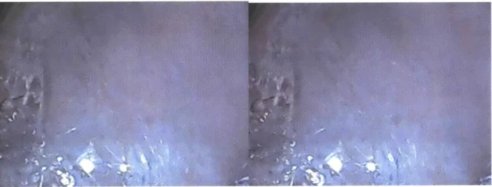
3.1.8 RESULTS OF LEAKING WITH SALINE HOT FEED
Upon inspection of the pictures, crystal can be observed gradually building as seen in Fig. 6. Upon unclamping the polycarbonate plate from the module, it was discovered that no salt was deposited on the MID membrane. Therefore, no fouling was observed. Instead, salt had deposited on the exterior surface
allowed hot liquid solution and vapor to escape the system and deposit salt on the exterior of the polycarbonate glass. This likely prevented bulk nucleation and particulate deposits on the MD membrane.
Figure 5. Before (left) and after (right) of crystal buildup on the exterior of the polycarbonate glass due to solution leaking at the junction of the hot feed and the polycarbonate plate.
3.1.9 PRESSURE DROP DUE TO NEW FILTER
The MD membrane was replaced. Silicone was reapplied to the junction connecting the hot feed with the polycarbonate plate to plug leaking. The silicone was allowed to dry for 24 hours. The 40 L tank was
emptied and refilled with 26.5 L of distilled water to clean the system of unwanted contaminants. A
metal grid was placed at the 40 L tank flow outlet to prevent the plastic bag from blocking flow. A newly arrived filter with casing was used to replace the old filter and casing to stop significant system leaking. The threads of the newly arrived filter were reinforced with Teflon tape to improve the watertight fit. The pump was started. Because this filter casing has smaller channels than the worn filter casing, smaller tubing was used to connect the new filter to the system. The smaller tubing in the system is responsible for a head loss resulting in a decrease in flow rate of roughly 0.2 GPM (0.8 LPM). This
pressure difference is considered negligible for the purposes of this experiment. Hot feed flow rate was 2.66 GPM (10 LPM).
Figure 6. Small tube flow channels for new filter.
3.1.10 LEAKING AT Low TEMPERATURE REVISITED
Leaking was discovered in tubing near the junction of the hot feed and the polycarbonate plate. Leaking would decrease internal system pressure, decrease local temperature, and allow for both water vapor and
liquid solution to escape the system in future high temperature experiments. As such, these conditions are not ideal for inciting particulate fouling. The pump was turned off. The joints at the site of tubing were tightened in order to stop the leaking, but failed in torsion. The plastic joint elements were replaced with new parts. The pump was turned on to check for leaks. Leaking was discovered at the circumference of the cutout in the polycarbonate plate through which the in-situ camera observed the MD membrane. Due to time constraints, super glue rather than silicone was applied to the circumference of the location of the in-situ camera just in front of the MD membrane because super glue solidifies in 20 minutes (as opposed to 24 hours).
3.1.11 NEW BARRIER FOR HEATER REVISITED
A new cylindrical cage was created for the heater using similar mesh grid material. The heater and the casing were placed inside a plastic bag. The plastic bad was filled with 3 L of distilled water and placed inside the 40 L tank to sufficiently submerge the heater in the system feed fluid. A metal grid was placed at the 40 L tank flow outlet to prevent the plastic bag from blocking flow. The temperature control system was turned on, and the pump was turned on. Leaking was discovered at the circumference of the cutout in the polycarbonate plate through which the in-situ camera observed the MD membrane. Leaking would decrease internal system pressure, decrease local temperature, allow for both water vapor and liquid solution to escape the system, and allow for salt buildup in the camera's vantage point in future high temperature experiments. As such, these conditions are not ideal for inciting or observing particulate fouling. The pump and the temperature control unit were turned off Silicone was applied to the circumference of the cutout in the polycarbonate plate through which the in-situ camera observed the MD membrane. The silicone was allowed to dry for 24 hours. The heater, cage, and surrounding plastic bag were removed from the 40 L tank to prevent corrosion. In the process of removing the heater, the heater came into contact with and burned a hole in the bag. The hole in the bag was patched with tape to reestablish the integrity of the solution's separation from the heater.
The pump was started. Leaking was discovered at the tubing just before the junction of the hot feed and the polycarbonate plate. The leaking produced a system loss of about 0.05 mL per minute (1 droplet per minute). This loss was considered negligible for the purposes of this experiment. A new cylindrical cage was created for the heater using similar mesh grid material. The heater and the casing were placed inside
a plastic bag. The plastic bad was filled with 3 L of distilled water and placed inside the 40 L tank to sufficiently submerge the bag in the system fluid. The temperature control system was turned on. The system was allowed to heat to a set point temperature of 70 'C after about 5 hours.
3.1.12 SECOND EXPERIMENTAL RUN WITH SALINE HOT FEED
While the system heated, 86.5 g of calcium chloride were measured out on a mass scale in increments of about 15 g and poured into a 1 L container of distilled water. Similarly, 251.2 g of sodium sulfate were measured out on a mass scale in increments of about 30 g and poured into a 1 L container of distilled water. The sodium chloride was crushed to a fine powder before pouring to minimize the amount of salt crystal formation in solution. The sodium sulfate was poured into the container gradually so as to prevent crystal nucleation in solution. The solution was stirred using an electromagnetic stirring rod until all of the salt had dissolved.
Once the system had reached the desired steady state temperature of 70 'C, programs that measure system temperature and permeate mass were started. The solution of calcium chloride was poured into the flowing water in the 40 L tank. About 10 minutes later, the sodium sulfate was poured into the flowing water in the 40 L tank. The in-situ camera was used to take pictures of the MD membrane every 5 minutes for 4 hours.
3.1.13 INCREASING SALT CONCENTRATION OF SALINE HOT FEED
No fouling was observed after the first hour. To promote particulate fouling, 50% more of each salt was added to the 40 L tank. 43.3 g of calcium chloride were measured out on a mass scale in increments of about 15 g and poured into a 1 L container of distilled water to prevent premature salt crystallization in the system. Similarly, 125.6 g of sodium sulfate were measured out on a mass scale in increments of about 30 g and poured into a 1 L container of distilled water to prevent premature salt crystallization in the system. The sodium chloride was crushed to a fine powder before pouring to minimize the amount of salt crystal formation in solution. The sodium sulfate was poured into the container gradually so as to
all of the salt had dissolved. The solution of calcium chloride was poured into the flowing water in the 40 L tank. About 10 minutes later, the sodium sulfate was poured into the flowing water in the 40 L tank.
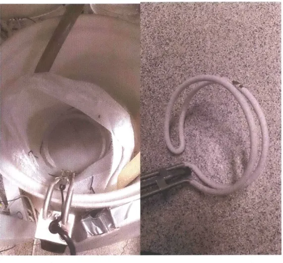
3.1.14 SALT BUILDUP ON HEATER
The in-situ camera was used to take pictures of the MD membrane every 5 minutes for the remaining 2.5
hours. After the experiment concluded, the pump was turned off, the temperature control unit was turned off, and the heater was removed from the 40 L tank. Upon inspection of the heater, it was clear that solution had infiltrated the plastic bag. Salt had crystalized around the heater. Upon inspection of the plastic bag, it was discovered that the tape used to patch a previously burned hole had loosened. As a result, no fouling was observed. Due to time constraints, the experiment was not repeated for a third time.
Figure 7. Before (left) and after (right) of the MD membrane did not reveal any fouling.
Figure 8. Salt buildup on the heater.
3.2 CAMERA SETUP
Due to low image resolution and definition, fine details in camera images were unclear. The focus of the camera was adjusted manually by turning a knob on the camera. The manual focus limited control of focus on fine details on the membrane surface. Moreover, the camera's focus was not uniform. Additionally, 200x camera magnification capabilities were insufficient to observe micropores in the hydrophobic MD membrane.
3.3 PERMEATE MASS VS. TIME
The findings from measurements of permeate mass agree with the observation that no fouling occurred in the second full experiment involving salts. As shown in Fig. 9, the system produced permeate at a constant rate of 0.5 mg/s between the 15-minute mark and the 2-hour mark. The system produced permeate at a constant rate of 11 mg/s between the 2-hour-1 5-minute mark and the 3-hour mark. The system produced permeate at a constant rate of 13 mg/s between the 3-hour mark and the 4-hour-10-minute mark. The first spike at the 15-4-hour-10-minute mark coincides with the time at which the first solution of calcium chloride was added to the system. The second spike at the 2 hour and 5 minute mark does not coincide with the addition of the second sample of either solution. Observed spikes in mass readings can be attributed to physical perturbations in the system from manual system adjustments and system management.
I
180 160 140 100 80 60 40 20 MO00 01:00:00 02:0000 03:00:00 Time (hh:tmiss) 0:00 05:00:00Figure 9. Measured permeate mass vs time for full experimental run on 5/16/2017.
25
CONCLUSIONS
Experiments were conducted with a solution of separately mixed Na2SO4 and CaCl2 in DI water and then
mixed together to form the hot feed solution. Persistent leaking in the system required continued trouble-shooting and hole patching through part replacement, silicone application, and super glue application. Due to failed efforts to prevent contact between the heater and surrounding barriers, contamination of the system resulted in catastrophic failure. Due to failed efforts to prevent contact between the heater
and the solution, premature nucleation and crystal growth occurred in solution thus preventing fouling.
Future experiments must improve precautionary efforts maintaining the system's watertight integrity, and improve efforts to distribute heat at a shallow temperature gradient throughout the solution. Additionally, future experiments should improve image quality by making use of a microscopic camera with automatic focusing or digital focus control, magnification capabilities greater that 200x (600x recommended), and appropriate stability. It is recommended that future researchers schedule trouble-shooting for the heater and relevant barriers with greater priority than all other elements of trouble shooting. Failure involving heater elements resulted in catastrophic experimental failures, caused destruction of vital parts, and required time-intensive reactionary steps. Trouble-shooting heater elements early on will allow future researchers to order potentially vital replacement parts early, and best prepare them to react to future failures. It is also recommended that experiments be planned with an allowance of ample time for troubleshooting and repeated runs ahead of deadlines.
REFERENCES
[1] David M. Warsinger, Jaichander Swaminathan, Elena Guillen-Burrieza, Hassan A. Arafat, and John H. Lienhard V. Scaling and fouling in membrane distillation for desalination applications: A review. Desalination, 356:294-313, 2014.
[2] Gisele Azimi, Yuehua Cui, Alina Sabanska, and Kripa K Varanasi. Scale-resistant surfaces:
Fundamental studies of the effect of surface energy on reducing scale formation. Applied Surface
Science, 313:591-599, 2014.
[3] Abdullah Alkhudhiri, Naif Darwish, and Nidal Hilal. Membrane distillation: A comprehensive
review. Desalination, 287:2-18, 2012.
[4] Saqib Shirazi, Che-Jen Lin, and Dong Chen. Inorganic fouling of pressure-driven membrane
processes - A critical review. Desalination, 250(1):236-248, 2010.
[5] Gisele Azimi, Yuehua Cui, Alina Sabanska, and Kripa K Varanasi. Scale-resistant surfaces:
Fundamental studies of the effect of surface energy on reducing scale formation. Applied Surface
Science, 313:591-599, 2014.
[6] Miray
Celikbilek,
Ali Ergin Ersundu, and Suheyla Aydn. Crystallization Kinetics of AmorphousMaterials. INTECH Open Access Publisher, 2012.
[7] D.E.M. Warsinger, J. Swaminathan, L. Maswadeh, and J.H. Lienhard V, "Superhydrophobic
Condenser Surfaces for Air Gap Membrane Distillation," J. Membrane Sci., online 10 June 2015, 492:578-587, 15 Oct. 2015.
[8] Marek Gryta. Effect of iron oxides scaling on the MD process performance. Desalination,
216(1-3):88-102, 2007.
27