HAL Id: tel-02269062
https://hal.univ-grenoble-alpes.fr/tel-02269062
Submitted on 22 Aug 2019
HAL is a multi-disciplinary open access archive for the deposit and dissemination of sci-entific research documents, whether they are pub-lished or not. The documents may come from teaching and research institutions in France or abroad, or from public or private research centers.
L’archive ouverte pluridisciplinaire HAL, est destinée au dépôt et à la diffusion de documents scientifiques de niveau recherche, publiés ou non, émanant des établissements d’enseignement et de recherche français ou étrangers, des laboratoires publics ou privés.
Verification of Parametric Properties
Yoann Blein
To cite this version:
Yoann Blein. ParTraP: A Language for the Specification and Runtime Verification of Parametric Properties. Software Engineering [cs.SE]. Université Grenoble Alpes, 2019. English. �tel-02269062�
THÈSE
Pour obtenir le grade de
DOCTEUR DE LA
COMMUNAUTÉ UNIVERSITÉ GRENOBLE ALPES
Spécialité : Informatique Arrêté ministériel : 25 mai 2016
Présentée par
Yoann BLEIN
Thèse dirigée par Yves LEDRU, Professeur Université Grenoble Alpes
et codirigée par Lydie DU BOUSQUET, Professeur Université Grenoble Alpes
préparée au sein du Laboratoire d'Informatique de Grenoble dans l'École Doctorale Mathématiques, Sciences et
technologies de l'information, Informatique
ParTraP : Un langage pour la spécification et
vérification à l'exécution de propriétés
paramétriques
ParTraP: A Language for the Specification
and Runtime Verification of Parametric
Properties
Thèse soutenue publiquement le 15 avril 2019, devant le jury composé de :
Monsieur YVES LEDRU
PROFESSEUR, UNIVERSITE GRENOBLE ALPES, Directeur de thèse
Madame LYDIE DU BOUSQUET
PROFESSEUR, UNIVERSITE GRENOBLE ALPES, Co-directrice de thèse
Monsieur JULIEN SIGNOLES
INGENIEUR CHERCHEUR, CEA LIST - GIF-SUR-YVETTE, Rapporteur
Madame VIRGINIE WIELS
MAITRE DE RECHERCHE, ONERA CENTRE MIDI-PYRENEES, Rapporteur
Monsieur SADDEK BENSALEM
PROFESSEUR, UNIVERSITE GRENOBLE ALPES, Président
Monsieur JEAN-MARC JEZEQUEL
PA R T R A P : A L A N G U A G E F O R T H E S P E C I F I C AT I O N A N D R U N T I M E V E R I F I C AT I O N O F PA R A M E T R I C P R O P E R T I E S
Design, Semantics and Case Study y oa n n b l e i n
© February 2019
s u p e r v i s o r s: Yves Ledru
A B S T R A C T
Runtime verification is a promising technique to improve the safety of complex systems. These systems can be instrumented to produce ex-ecution traces enabling us to observe their usage in the field. A signif-icant challenge is to provide software engineers with a simple formal language adapted to the expression of their most important require-ments. In this thesis, we focus on the verification of medical devices. We performed a thorough analysis of a worldwiused medical de-vice in order to identify those requirements, as well as the precise nature of its execution traces. In the light of this study, we propose ParTraP, a formally defined language dedicated to property speci-fication for finite traces. It is designed to be accessible to software engineers with no training in formal methods thanks to its simplicity and declarative style. The language extends the specification patterns originally proposed by Dwyer et al. with parametrized constructs, nested scopes, real-time and first-order quantification. We also pro-pose a coverage measurement technique for ParTraP, and we show that coverage information provides insights on a corpus of traces as well as a deeper understanding of temporal properties. Finally, we describe the implementation of an Integrated Development Environ-ment for ParTraP, which is available under a free and open-source license.
La vérification à l’exécution est une technique prometteuse pour amé-liorer la sûreté des systèmes complexes. Ces systèmes peuvent être instrumentés afin qu’ils produisent des traces d’exécution permettant d’observer leur utilisation dans des conditions réelles. Un défi impor-tant est de fournir aux ingénieurs logiciel un langage formel simple adapté à l’expression des exigences les plus importantes. Dans cette thèse, nous nous intéressons à la vérification de dispositifs médicaux. Nous avons effectué l’analyse approfondie d’un dispositif médical utilisé mondialement afin d’identifier les exigences les plus impor-tantes, ainsi que la nature précise des traces d’exécution qu’il produit. À partir de cette analyse, nous proposons ParTraP, un langage dé-fini formellement et dédié à la spécification de propriétés sur des traces finies. Il a été conçu pour être accessible à des ingénieurs logi-ciels non qualifiés en méthodes formelles grâce à sa simplicité et son style déclaratif. Le langage étend les patrons de spécification initia-lement proposé par Dwyer et al. avec des opérateurs paramétriques et temps-réel, des portées emboîtables, et des quantificateurs de pre-mier ordre. Nous proposons également une technique de mesure de couverture pour ParTraP, et montrons que le niveau de couverture d’une propriété temporelle permet de mieux la comprendre, ainsi que le jeu de traces sur lequel elle est évaluée. Finalement, nous dé-crivons l’implémentation d’un environnement de développement in-tégré pour ParTraP, qui est disponible sous une licence libre.
P R E FA C E
This thesis presents my research conducted in the VASCO team at Laboratoire d’Informatique de Grenoble, to pursue a PhD in Com-puter Science from the doctoral school “Mathématiques, Sciences et Technologies de l’Information, Informatique” of the Université Grenoble-Alpes. My research activities have been supervised by Yves Ledru and Lydie du Bousquet, both professors at the Université Grenoble-Alpes, and funded by the Agence Nationale de la Recherche (ANR-15-CE25- 0010).
This work led to the following publications:
[1] Yoann Blein, Arnaud Clere, Fabrice Bertrand, Yves Ledru, Roland Groz, and Lydie du Bousquet. “Improving Trace Generation and Analysis for Medical Devices.” In: 2017 IEEE International Conference on Software Quality, Reliability and Secu-rity Companion, QRS-C 2017, Prague, Czech Republic, July 25-29,
2017. IEEE, 2017, pp. 599–600. doi:10.1109/QRS-C.2017.135. [2] Yoann Blein, Yves Ledru, Lydie du Bousquet, and Roland Groz.
“Extending specification patterns for verification of paramet-ric traces.” In: Proceedings of the 6th Conference on Formal Meth-ods in Software Engineering, FormaliSE 2018, collocated with ICSE
2018, Gothenburg, Sweden, June 2, 2018. Ed. by Stefania Gnesi,
Nico Plat, Paola Spoletini, and Patrizio Pelliccione. ACM, 2018, pp. 10–19. doi:10.1145/3193992.3193998.
[3] Ansem Ben Cheikh, Yoann Blein, Salim Chehida, Germán Vega, Yves Ledru, and Lydie du Bousquet. “An Environment for the ParTraP Trace Property Language (Tool Demonstration).” In: Runtime Verification - 18th International Conference, RV 2018, Li-massol, Cyprus, November 10-13, 2018, Proceedings. Ed. by Chris-tian Colombo and Martin Leucker. Vol. 11237. Lecture Notes in Computer Science. Springer, 2018, pp. 437–446. doi:10.1007/ 978-3-030-03769-7_26.
[4] Yves Ledru, Yoann Blein, Lydie du Bousquet, Roland Groz, Ar-naud Clere, and Fabrice Bertrand. “Requirements for a Trace Property Language for Medical Devices.” In: 2018 IEEE/ACM International Workshop on Software Engineering in Healthcare Sys-tems, SEHS@ICSE 2018, Gothenburg, Sweden, May 28, 2018. ACM, 2018, pp. 30–33. url:http://ieeexplore.ieee.org/document/ 8452638.
A C K N O W L E D G M E N T S
First of all, I would like to thank the members of my PhD thesis jury for the time they have taken to examine my work, for their meaning-ful comments and questions, and for participating in the defense. I would also like to thank my two PhD advisors, Yves Ledru and Lydie du Bousquet, for the remarkable amount of time they took to teach me the practice of research, and to help me improve my work. During this time, they have always been patient and kind, for which I am immensely grateful. They were also here to support me during the difficult yet rewarding experience that a PhD can be.
I also thank Arnaud Clère and Fabrice Bertrand for their availability, their helpful contributions, and for sharing their expertise.
A special thank to my close friends, Simon and Hugo, who were also PhD students at the time. Whether they were about our ongoing research, about our experiences as PhD students, or flat-out pedantry, our endless discussions were always a pleasure. I will miss them. Finally, I deeply thank my mother who has always supported my decisions and believed in me accomplishing them.
C O N T E N T S
1 i n t r o d u c t i o n 1
1.1 Context . . . 1
1.2 Thesis Statement . . . 3
1.3 Contributions . . . 4
2 c o n t e x t: an industrial case study 7 2.1 Presentation ofTKA . . . 8
2.2 Verification and Validation Constraints for Medical De-vices . . . 10
2.3 Blue Ortho Methodology forTKADevelopment . . . . 11
2.3.1 User Level: From Intended Use to Validation . . 12
2.3.2 Technical Level: From Design to Verification . . 12
2.3.3 Implementation Level: From Development to Unit Testing . . . 13
2.4 States and Traces . . . 13
2.4.1 Hierarchical Finite State Machine . . . 13
2.4.2 Execution Traces . . . 13
2.5 Post-Market Surveillance . . . 15
2.5.1 Misuse Surveillance . . . 15
2.5.2 Usage Studies . . . 16
2.6 The Need for Automated Trace Analysis . . . 17
2.6.1 Why Trace Analysis . . . 17
2.6.2 Limitations of the Current Approaches . . . 18
2.7 Towards Automated Trace Verification . . . 19
2.7.1 A Structured Tracing Library . . . 19
2.7.2 A Language for Trace Verification . . . 19
3 r e q u i r e m e n t s a na ly s i s f o r t k a 21 3.1 Studied Requirements . . . 21
3.1.1 Inappropriate Sources of Requirements . . . 21
3.1.2 Relevant and Representative Requirements . . . 24
3.2 List of Representative Properties . . . 25
3.3 Types of Properties and Their Use . . . 26
3.4 Analysis . . . 28
4 r u n t i m e v e r i f i c at i o n 31 4.1 Specification of the System Behavior . . . 31
4.2 Software Instrumentation . . . 33
4.3 Verifying Executions . . . 34
5 t e m p o r a l s p e c i f i c at i o n l a n g ua g e s 37 5.1 Overview . . . 37
5.1.1 Pattern Systems . . . 37
5.1.2 Linear Temporal Logics . . . 39
5.1.3 Finite State Machines . . . 41
5.1.4 Rule-Based Systems . . . 41
5.1.5 Hybrid . . . 41
5.1.6 Stream Computation . . . 42
5.2 Comparison and Discussion . . . 42
6 t h e pa r t r a p l a n g ua g e 47 6.1 Trace Model . . . 47 6.2 Language Features . . . 48 6.2.1 Event Descriptors . . . 48 6.2.2 Patterns . . . 50 6.2.3 Scopes . . . 52 6.2.4 Timed Variants . . . 55 6.2.5 Quantifiers . . . 55 6.2.6 Event Selection . . . 56 6.2.7 Logical Operators . . . 57
6.3 Specification Examples: TKAProperties . . . 57
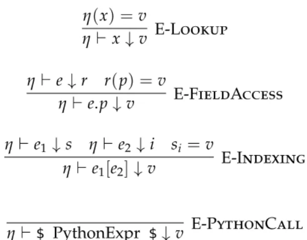
6.4 Characteristics . . . 60 7 f o r m a l d e f i n i t i o n o f pa r t r a p 63 7.1 Expression Language . . . 63 7.2 Syntax . . . 64 7.3 Semantics . . . 66 7.3.1 Preliminary Definitions . . . 66
7.3.2 Events Extraction and Time Slicing . . . 67
7.3.3 Semantic Rules . . . 68 7.3.4 Derived Constructs . . . 69 8 pa r t r a p i m p l e m e n tat i o n a n d e x p e r i m e n t s 71 8.1 Trace Format . . . 71 8.2 Command-Line Interpreter . . . 72 8.2.1 Implementation Strategies . . . 73 8.2.2 Experiments . . . 74 8.3 User Environment . . . 74 8.3.1 Tool Generation . . . 75
8.3.2 Integrated Development Environment . . . 76
9 c ov e r a g e m e a s u r e m e n t f o r pa r t r a p 79 9.1 Measuring Coverage by Case Disjunction . . . 80
9.2 Term Rewriting System . . . 81
9.2.1 Core Operators . . . 81
9.2.2 Rewrite Rules . . . 82
9.2.3 Implementation . . . 84
9.3 Coverage Examples: TKA Properties . . . 84
c o n t e n t s xi
10 c o n c l u s i o n a n d p e r s p e c t i v e s 91 10.1 Summary . . . 91 10.2 Future Research Directions . . . 92
L I S T O F F I G U R E S
Figure 2.1 Usage of the TKA product during a surgery
(photography from Blue Ortho) . . . 8
Figure 2.2 Pointer and trackers usage during the hands-on sessihands-on . . . 9
Figure 2.3 Screenshots of theTKAinterface at different steps 10 Figure 2.4 Blue Ortho’s V-Model forTKA . . . 11
Figure 2.5 ATKAgraphical component for numerical val-ues display . . . 13
Figure 2.6 Short extract of a possible instantiation of the TKAstate machine . . . 14
Figure 2.7 Excerpt of an execution trace recorded during a surgery withTKA . . . 15
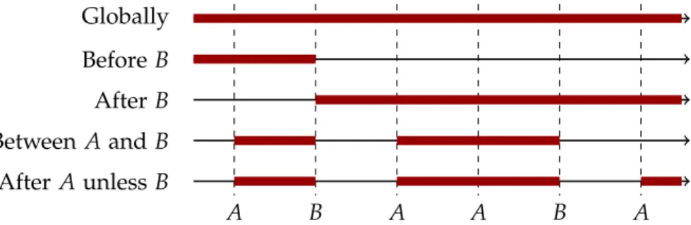
Figure 5.1 The 8 property patterns proposed by Dwyer et al. 37 Figure 5.2 Graphical representation of the 5 scopes pro-posed by Dwyer et al. . . 38
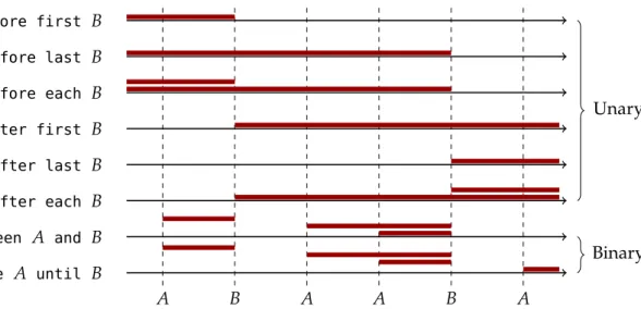
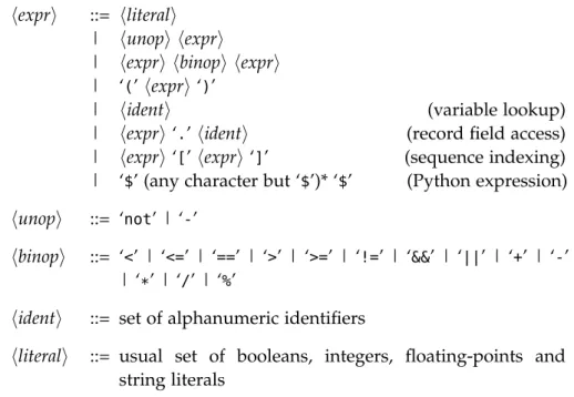
Figure 6.1 Graphical representation of ParTraP scopes . 52 Figure 7.1 Syntax of expressions . . . 63
Figure 7.2 Syntax of ParTraP . . . 65
Figure 8.1 Example ofJSONtrace . . . 72
Figure 8.2 Architecture of the ParTraP toolset . . . 75
Figure 8.3 Screen capture of the environment . . . 76
Figure 9.1 Graphical representation of the 5 valid scenar-ios in Property 12 . . . 87
L I S T O F TA B L E S Table 3.1 Classification of the 15 selected properties . . . 28
Table 5.1 Comparison of several temporal specification languages . . . 43
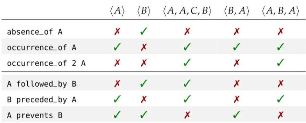
Table 6.1 Examples of pattern satisfaction for various traces . . . 50
Table 7.1 Precedence of ParTraP operators on properties 64 Table 8.1 Evaluation times for different properties (in seconds) . . . 77
A C R O N Y M S
ANR Agence Nationale de la Recherche DNF Disjunctive Normal Form EBNF Extended Backus–Naur Form FDA Food and Drug Administration FSM Finite State Machine
GUI Graphical User Interface
IDE Integrated Development Environment JSON JavaScript Object Notation
LGPL GNU Lesser General Public License LTL Linear Temporal Logic
MCPS Medical Cyber-Physical Systems TRS Term Rewriting System
1
I N T R O D U C T I O N
1.1 c o n t e x t
A new generation of medical devices emerges to support increasingly more complex medical decisions and procedures. These Medical Cyber-Physical Systems (MCPS) combine data from novel sensors and existing modalities like scanners with elaborate software processing to assist caregivers, in the same way flight management systems help a pilot flying planes. For instance, Blue Ortho’s MCPS allows performing Total Knee Arthroplasty more precisely (TKA, i.e. the placement of a femoral and tibial knee prosthesis), potentially divid-ing the number of revisions by two [67]. This is very beneficial to the patients because the replacement of a first prosthesis by another one incurs significant damage to the bones and very few patients can walk normally after a TKA revision.
Unfortunately, innovation and safety of suchMCPSis hindered by the current software verification practices of the MCPS industry. The ex-ample of the Therac-25, a radiation therapy machine which killed or injured several patients, shows that bad development practices may lead to catastrophic situations [52]. As a result of this tragedy, na-tional health agencies have reinforced their expectations on software development practices for medical devices, which are enforced with thorough audits conducted pre- and post-market. To enable the de-velopment of certifiable medical devices, several initiatives have pro-moted the use of formal methods.
Formal methods refer to mathematically based techniques for the specification, development and verification of software and hardware systems. The specifications used in formal methods are well-formed statements in a mathematical logic and the verifications are rigorous deductions in that logic. Successful deductions correspond to proofs that a system respects certain properties, such as its correctness with respect to its specification. Formal methods encompass highly diverse techniques ranging from fully automated, such as static type systems in programming languages, to completely manual, such as some of the most popular proof assistant.
Some formal methods have demonstrated their effectiveness for decades in the most safety-critical industries (e.g. defense, avionics [72], space [15], railways [33], or nuclear power plants [60]), but they failed to gain broader adoption. In the medical industry, the
maker Challenge [56] recently demonstrated that it is theoretically, if not economically, possible to perform full verification of some med-ical devices which interact in sufficiently restricted and controlled ways with their environment. However, full formal verification of new-generationMCPSswould be very difficult to achieve. This can be attributed to several factors:
• Caregivers use various combinations of medical devices and adapt procedures to fulfill the task at hand, making it difficult and costly to completely formalize, hence verify, the whole sys-tem a priori.
• Current regulations, such asISO62304[44], do not ask for proofs of safety: pre-market validation is based on development pro-cess and risk analysis verifications; post-market surveillance can be limited to informal follow-ups. Nonetheless, some regulatory administrations like the United States Food and Drug Admin-istration (FDA) are interested in evidences of safety, i.e. factual data on the actual device.
• Last but not least, a number of verification tools only target the C or Java programming languages, such as Frama-C [50] or Krakatoa [55], while theMCPS industry mainly uses C++for its combination of abstraction and performance features (C being limited to embedded medical software and Java to interoper-ability with hospital information systems). Crocker gave a short overview of the existing approaches and difficulties faced for verifying C++programs [22].
Most of the pioneering works for bringing formal methods to the MCPS field are performed by academic research groups, and signif-icant efforts need to be done in order to transfer these formal ap-proaches into industrial practice. TheMODMEDresearch project is one of those efforts, and this Ph.D. research was part of it. The project gathers a research laboratory, a medical device manufacturer and a software provided for medical devices, with the goal of improving evaluation of MCPS safety by introducing formal verification to the field. To maximize its relevance, MODMED research work is focused on the study of a worldwide usedMCPSmade available by one of the partners. Another key aspect of theMODMED approach is the use of so-called “lightweight” formal methods to introduce formal verifica-tion.
Since several years, a part of the formal methods community has pro-moted a “lightweight” approach to the use of formal methods. Based on the analysis of D. Jackson and J. Wing [45] which stated the pro-hibitive cost of full verification, the lightweight approach to formal methods advocates for:
1.2 thesis statement 3
• partial application of formal methods techniques, including specification of a subset of the system properties based on risk evaluation and cost-effectiveness,
• the choice of a language which allows automated tool sup-port, or
• the use of tools that partially check the system but actually find bugs.
By trading completeness in favor of automation, lightweight tech-niques make the use of formal methods practical and within reach of a wider audience of software engineers. Runtime verification is an example of those techniques.
Roughly speaking, runtime verification is a set of theories, techniques and tools aiming towards efficient analysis of a system’s executions and guaranteeing their correctness with respect to a specification. Practically, runtime verification consists in taking as input some sys-tem representation, performing some analysis, and yielding a verdict indicating the correctness of the system in addition to some form of feedback to the user. Runtime information must be directly obtained from the execution of the system and automatically analyzed. This ap-proach perfectly matches the previous description of lightweight for-mal method as it only partially checks the system (a single execution at a time), but does not require a full model and can be completely automated.
1.2 t h e s i s s tat e m e n t
MCPSs are powerful systems that can be easily equipped with elab-orate tracing facilities. Exploiting their execution traces and sensor data can provide us with an unbiased and precise understanding of their behavior in the field. Consequently, runtime verification seems particularly fit to the task at hand:
1. Systematic and automatic verification of execution traces can significantly improve the post-market surveillance of such sys-tems, which is usually limited to ineffective and informal follow-ups of the device users. Trace analysis brings empirical evi-dence that the system exhibits the expected behavior. Moreover, it allows to understand how the system is actually used. For instance, it could allow validating safety-related assertions on users behavior [11] or hardware longevity [70].
2. It can complement the process-based validation of medical de-vices. Dedicated tools can use models as reference for assessing the functional coverage of existing tests (manual system tests as well as automated “white-box” unitary tests). This would con-tribute to establish the safety of the system by complementing
the test report reviews, based on code coverage, with an inde-pendent measure of the requirements captured in the model and covered by tests.
Recording execution traces is already a standard practice in most in-dustrial software, but their effective exploitation requires adequate tools. A significant challenge is to provide medical software engineers with a simple formal language adapted to the expression of their most important requirements. In the field of runtime verification, sev-eral proposals — such as Dwyer’s patterns [28] — allow expressing temporal properties at a higher level than temporal logic. These pro-posals are not directly suitable for the data-rich traces found in the medical domain.
1.3 c o n t r i b u t i o n s
In this thesis, we report on the analysis of a worldwide-used MCPS for total knee arthroplasty. After presenting the verification process for this device and highlighting its limitations, we explain how trace analysis can be used at several stages of development to overcome those limitations in Chapter 2. Next, we describe our process to iden-tify requirements for a property language adapted to this MCPS in Chapter 3. After a brief presentation of runtime verification in Chap-ter 4, we show that existing temporal specification languages focus only on a specific subset of the identified requirements, and that a more practical solution can be designed in Chapter 5.
Based on the previous analysis, we propose ParTraP, a language dedicated to property specification for finite traces. Its design was driven by two objectives: allowing elegant specification of properties on traces produced by MCPSs, and being easy to apprehend by engi-neers with no training in formal methods. ParTraP uses a declarative style with a user-friendly syntax. It features intuitive temporal oper-ators derived from the ones proposed by Dwyer et al. [28], with the difference that they can be composed for increased expressiveness. The language also features first-class support for data-carrying events with arbitrarily complex data layouts. ParTraP’s semantics is fully formalized and implemented in a compiler packaged together with an Integrated Development Environment (IDE). It is available online under a free and open-source license. Chapter 6 shows an informal presentation of the language, Chapter 7 gives its formal semantics, and Chapter 8 describes itsIDEcompanion.
We also propose a technique to evaluate the coverage of properties written in ParTraP over a set of traces in Chapter 9. Despite our efforts to keep ParTraP simple, correctly specifying temporal prop-erties remains delicate. Complex propprop-erties may contain subtle cases, intricate to detect. Coverage information exposes them and the role
1.3 contributions 5
they played in the satisfaction of a property. In particular, errors in properties can be detected. We demonstrate this capability through several examples, and show that it can also help refining proper-ties and detecting malformed traces. This coverage evaluation relies on the decomposition of properties into Disjunctive Normal Form, which is itself accomplished by a Term Rewriting System specifically designed for that purpose.
Chapter 10 concludes this thesis and discusses possible research di-rections and applications for ParTraP.
2
C O N T E X T : A N I N D U S T R I A L C A S E S T U D Y
My Ph.D. research took place within the framework of the MODMED research project, funded by the Agence Nationale de la Recherche (ANR), the French national research agency. This project gathered three part-ners located in Grenoble, France:
1. MinMaxMedical, a company specialized in software for medical devices,
2. Blue Ortho, which develops medical devices, and
3. Laboratoire d’Informatique de Grenoble, a research laboratory. Its main objective was to improve the evaluation ofMCPSssafety and performance in the field by the mean of automated model-based ver-ification of execution traces. The motivations behind this strategy were threefold. First, recording executions ofMCPSsis relatively easy, thanks to their power and flexibility. Second, systematic and auto-matic verification of execution traces can significantly improve the post-market surveillance of such systems, which is usually limited to ineffective and informal follow-ups of the device users. Trace analysis brings empirical evidence that the system exhibits the expected be-havior, and it allows understanding how the system is actually used. Finally, it can complement the process-based validation of medical devices and contribute to establish their safety before reaching the market.
To ensure the relevance of its research to the field, theMODMEDproject was centered around an industrial case study. The medical device un-der study was TKA, a surgery assistant designed and developed by Blue Ortho for Exactech, a US-based implant manufacturer. The TKA product was chosen for this project because, on the one hand, it ap-pears as representative of new generation medical devices, and on the other hand, it has been used worldwide for several years. Blue Ortho already acquired more than 10 000 traces of execution resulting from real surgeries, which provide a rich raw material for the MODMED project.
In this chapter, we first presentTKA in Section 2.1. Then, Section 2.2 briefly describes the international obligations for developing medi-cal devices, and Section 2.3 details the methodology employed by Blue Ortho to meet those obligations. In Section 2.4 and Section 2.5, we describe the nature and role that execution traces currently play
in the life-cycle of TKA. Section 2.6 presents the potential benefits of trace verification for medical devices development, and how it fits in the product life-cycle. Section 2.7 concludes the chapter.
2.1 p r e s e n tat i o n o ft k a
Figure 2.1: Usage of the TKA product during a surgery (photography from
Blue Ortho)
TKA is an application to guide total knee arthroplasty surgeries, i.e. the replacement of both tibial and femoral cartilages with implants. Figure 2.1 shows TKA in use during a surgery. The system is com-posed of software, mechanical and electronic components. The station on the left includes a touchscreen and a stereo vision camera on top of it. Beside the station, the system also includes a set of trackers. They are firmly attached to the bones of the patient and their position and orientation can be detected by the camera. The camera also detects a pointer device, which is used to acquire the position of some anatom-ical points. Two trackers and the pointer device can be seen in more details in Figure 2.2. The whole system can be manipulated directly by the surgeon or their assistants through the touch screen, and us-ing the pointer device. Once the system has acquired all the necessary anatomic information, the surgeon can plan several cuts in order to place the prosthesis. The system will then help them to position cut-ting guides.
At a high level, performing a total knee arthroplasty withTKAmainly consists in the following sequence of operations during the surgery:
2.1 presentation oft k a 9
Figure 2.2: Pointer and trackers usage during the hands-on session
1. acquisition After fixing the trackers to the patient’s bones, the surgeon acquires a set of anatomic points by designating them with the pointer device. Other points require performing cer-tain movements with the patient’s leg, which are captured by the attached trackers. Once all the necessary points have been acquired, the system is able to construct a digital model of pa-tient’s anatomy. Several mechanisms and safeguards encoded in TKA software check that acquisitions are “correct” according to rules established by Blue Ortho. However, the software cannot judge whether the acquisitions correctly reflects the patient’s anatomy. Therefore, surgeons are also trained to appreciate the quality of the acquisitions themselves. Figure 2.3a shows the interface of TKA allowing to visualize some of the performed acquisitions.
2. decision By combining the constructed model of the patient’s anatomy and trackers position, TKA computes several metrics which are updated in live when the surgeon manipulates the patient. Thanks to this information, the surgeon is able to pre-cisely adjust its preoperative planning for implant size and po-sition. The interface displayed in Figure 2.3b allows the surgeon to set up and visualize their plan.
3. action The surgeon installs some cutting guides on the patient’s bones and adjusts them according to the information on screen. Thanks again to the live updating view,TKAdirects the process so that the position of cutting guides matches the plan up to a degree or a millimeter. Figure 2.3c shows the interface
corre-sponding to this step. Once the guides are setup, the surgeon proceeds to cut the bones.
(a) Acquisition (b) Planning (c) Positioning
Figure 2.3: Screenshots of theTKAinterface at different steps
Although this operation sequence appears very linear from the above description, the low-level order in which all the steps are performed is actually flexible and some of them may even be opted out. For in-stance, surgeons decide whether they want to acquire optional redun-dant anatomical points for additional confidence in the constructed digital model. The actual low-level ordering is computed at the begin-ning of a surgery according to surgeons’ preferences and their needs for the present surgery. The order in which surgeons prefer to op-erate is called a profile, and is defined by a Blue Ortho representative during an interview. This feature introduces significant complexity in the software but it is a key for the adoption of the device by surgeons, who all have a preferred way to operate.
From a technical standpoint, TKA software is entirely written in C++
and composed of about 250 classes. It runs on machines using a Mi-crosoft Windows operating system, to which the camera and screen are connected.
2.2 v e r i f i c at i o n a n d va l i d at i o n c o n s t r a i n t s f o r m e d i -c a l d e v i -c e s
Medical devices and their software are regulated by several interna-tional standards. Their development must follows a classical V-Model methodology complying with ISO13485[42], complemented with:
• an end-to-end requirements management complying with ISO 62304[44], and
• a risk analysis of the medical device complying with ISO14971 [43].
Before reaching clinics or hospitals in a country, medical devices must get certified by national or international drug agencies. The develop-ers of the medical device have to demonstrate that the development process and the product are compliant with the aforementioned
stan-2.3 blue ortho methodology fort k a d e v e l o p m e n t 11
dards. Most notably, they must justify the results of the risk analysis for each software component, and show that the test coverage of each component is appropriate for its established risk level. This audit pro-cess is quite thorough and usually lasts several months. Anecdotally, Blue Ortho reported that reviewers’ expectancies are high and that ev-ery objection or question they have must be answered with hard facts. Once the device has been certified and is used in production, the de-vice is audited again periodically, as well as for minor revisions. Medical device manufacturers are also expected to monitor all their devices in use, known as “post-market surveillance”. However, this requirement is vague and follow-ups are usually limited to informal follow-ups of the device users, often ineffective.
2.3 b l u e o r t h o m e t h o d o l o g y f o rt k a d e v e l o p m e n t
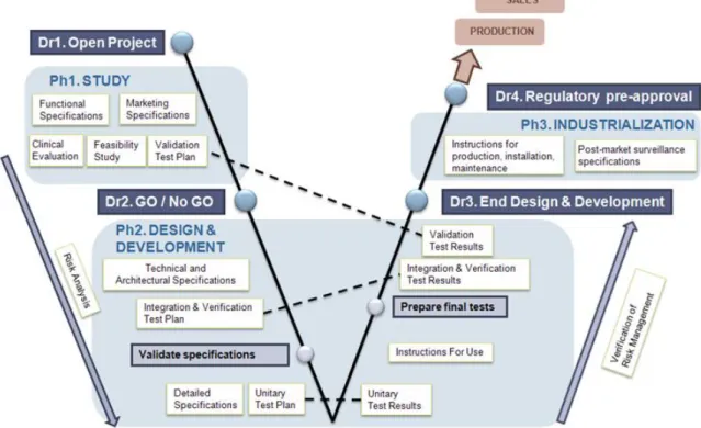
Blue Ortho followed a thorough methodology in the development of TKA, with a focus on quality beyond of what is expected from standard regulations. This methodology is based on a V-Model whose process is tweaked for the medical device industry. It is represented by the diagram in Figure 2.4, which was extracted from Blue Ortho Quality Management System. The Blue Ortho V-Model is split in 3
Figure 2.4: Blue Ortho’s V-Model forTKA
levels depicted by dashed lines. Each of them is detailed by one or several confidential documents. As they are audited by drug agencies, these documents are high quality references which describe precisely
the design and implementation of TKA’s software. From the least to the most detailed, we can name these 3 levels: User, Technical and Implementation.
2.3.1 User Level: From Intended Use to Validation
At the top-level, the design team, the development team and the qual-ity managers along with some end-users (surgeons) write a document called “Marketing Specifications”, describing the intended use of the product and the corresponding high-level user needs, along with a “Functional Specifications” document describing its components and high-level usability requirements. At the very end of the design and development procedure, the validation of the product will depend on the result of “validation tests” typically performed by surgeons on cadavers using a successfully verified device.
2.3.2 Technical Level: From Design to Verification
At the middle level, the design and development team together with the help of their engineering team write the “Technical Specifica-tions”. It is a confidential document describing the requirements on
This document is more frequently named by other medical devices manufacturers “Sofware Requirements Specification” to follow the United StatesFDA
terminology.
its software, and more specifically by detailing its technical functions, verification test plan, architectural design, interfaces, integration test plan, risk measures test plan, and technical traceability. Many of those are described through test scenarios and the “verification” of the product consists in performing all these scenarios manually and an-alyzing their results. “Technical Specifications” forTKA are 125 page-long and performing all verification tests, as required for major revi-sions of the product, takes approximately 1 person-month.
The wholeTKAsoftware is described through 32 groups named “Sys-tem Functions”. These 32 functions are further decomposed in a total of 319 test scenarios. They describe what is required to happen after each step, or at the end of a scenario. On average, there are 10 tests per function. Only 5 System Functions have more than 12 tests, and the most complex one has 46 tests. The effort necessary to test each case may greatly vary, depending on the number of initial environments. These tests focus on the system accuracy and the user workflow. Accu-racy cannot be tested with the medical device alone and is specifically tested with a specifically designed hardware test bench. Most system functions also include a test case where the tester is free to take un-specified user actions and to appreciate whether the resulting system behavior is normal. This illustrates the compromise between specify-ing tests with well-defined acceptance criteria (even informally) and the desire to verify the medical device under more situations without having time to precisely describe their inputs and outputs.
2.4 states and traces 13
2.3.3 Implementation Level: From Development to Unit Testing
At the lowest level, engineers write “Detailed Specifications” docu-ments for each software component in the form of unitary test plans. They implement the components and write unit tests for each compo-nent’s function. The nature of those components is very diverse, rang-ing from geometric computation to graphical display. For instance, the graphical component in Figure 2.5 is responsible for accurately displaying named numerical values with the appropriate unit in
var-ious languages, and tested accordingly. TKA software contains 250 Figure 2.5: ATKA
graphical component for numerical values display
C++ classes which source code also contains the unit tests. The ratio
“tests size over implementation size” can reach up to 3 depending on components. The test suite comprises more than 600 unit tests which are run automatically during several steps of the development. Unit test results are collected and verified manually before perform-ing the product verification. Beperform-ing able to run these tests and obtain repeatable test results allows Blue Ortho to manage the proliferation of user options (about 30 different screens and 60 options), and trans-lations (English, French, Spanish, German, Italian, and later Japanese, Korean, etc.). However, the limit of testing is well understood by Blue Ortho that takes test results as no more than “an evidence that the software performed well at least once”. Consequently, they put a lot of efforts in software design to improve its quality, like stati-cally tracking the many coordinate systems of geometrical primitives (anatomical axis and planes, physical instrument points, etc.) using dedicated types.
2.4 s tat e s a n d t r a c e s
2.4.1 Hierarchical Finite State Machine
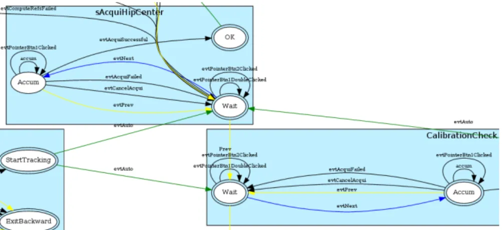
A notable example of Blue Ortho emphasis on design resulted in putting the responsibility to adaptTKAworkflow to the surgeon’s pro-file into a hierarchical finite state machine which models this work-flow and drives the whole user interface (from physical tools to graph-ical widgets). This state machine is dynamgraph-ically built according to the surgeon’s profile. The instantiated state machine is logged at the beginning of a TKA execution. Figure 2.6 shows a short extract of a possible instantiation of the state machine, with parent states in blue and child states in white. In the following, whenever we talk about the “state” of TKA, we refer to the current state of the instantiated finite state machine.
2.4.2 Execution Traces
To monitor how TKA devices are used on the market, Blue Ortho equipped them with a mechanism to record execution traces, which
Figure 2.6: Short extract of a possible instantiation of theTKAstate machine
are produced for each surgery. This mechanism was initially intro-duced to store sufficient information to understand the course of a surgery and possibly to identify failures. A trace reflects both the workflow of TKA software and of the surgery itself through a se-quence of events. The nature of these events is very diverse and includes communication with the sensors, interactions with the sur-geon, progress through the steps of the surgery, or complex compu-tation results.
TKAtraces are not particularly long: they are composed of about 3000 events on average. However, they are quite rich in data. Most of the events carry additional values, ranging from atomic values such as strings or numbers, to compound data such as 3D points or matrices. For instance, whenever the system acquires a cloud of points desig-nated by the surgeon through the pointing device, it produces a sin-gle event containing that whole set of points (about 400). Figure 2.7 shows an excerpt of such an execution trace recorded byTKA during a surgery, with interesting information highlighted. We can see that each event is time-stamped and that the aforementioned state ma-chine transitions are traced. A particular attention was paid to trace user input and sensors events because Blue Ortho wanted to be able to understand how the product would be used in the market. For instance, the last line contains the coordinates of the first point of a point cloud being accumulated.
Execution traces are also complemented with technical data such as screenshots of the graphical user interface taken at each step of the surgery, or the three-dimensional scene constructed from anatomic ac-quisitions. However, the traces contain little information about the in-ternal values of the program (variables) and its control flow (method calls). Also, raw data acquired by the sensors is completely absent. One of the objectives of the MODMEDproject is to provide the means to easily trace such information in future products, or major revisions of TKA.
2.5 post-market surveillance 15
MSG 2015.11.11-02:18:01.145 | OPEN
MSG 2015.11.11-02:18:01.145 | Version : 1.15.3 ...
MSG 2015.11.11-02:18:01.395 | [EventHandler::performStateEntry] Entering state : mainCasp MSG 2015.11.11-02:18:01.395 | [EventHandler::performStateEntry] Entering state : mainCasp.
Welcome ...
MSG 2015.11.11-02:18:02.659 | [EventHandler::performStateExit] Exiting state : mainCasp. Welcome
MSG 2015.11.11-02:18:02.846 | [EventHandler::performStateEntry] Entering state : mainCasp. Enter Patient Info
MSG 2015.11.11-02:18:11.207 | [BlueApp] Click on Btn Left at pos = (475,95) ...
MSG 2015.11.11-02:18:37.462 | [MainBlueWidget] Screen Btn Next clicked ...
MSG 2015.11.11-02:19:02.410 | [Profile::loadFromXML] file 'C:/.../Dr. XXX - ALL CUTS w ACB. bprofile' loaded successfully
...
MSG 2015.11.11-02:19:07.340 | [FoxDriver::connect] Device 166ec0dd01 connected ...
MSG 2015.11.11-02:19:43.859 | Marker Detected : 16aa1a9401, P001002 ...
MSG 2015.11.11-02:20:37.913 | [EventHandler::performStateExit] Exiting state : mainCasp. CalibrationCheck.Wait
MSG 2015.11.11-02:20:37.913 | [EventHandler::performStateEntry] Entering state : mainCasp. CalibrationCheck.Accum
MSG 2015.11.11-02:20:37.929 | [ 0] 0.0041657031046522519 64.562875356938733
11.860463388262414
Figure 2.7: Excerpt of an execution trace recorded during a surgery withTKA
Blue Ortho collects the traces of all surgeries conducted with TKA. The product is being used worldwide for several years and more than 10 000surgery traces have been collected. Currently, those traces are analyzed manually, but their increasingly large number is making that task less and less reliable.
2.5 p o s t-market surveillance
Once a medical device is certified for some market and actually used, Blue Ortho considers that analyzing the device usage in real surgeries is critical to ensure patient safety. For instance, they presented us a few studies on TKAthat were done thanks to the collected traces, but also examples of studies that could not be completed by lack of tools or methods.
2.5.1 Misuse Surveillance
As a general usability principle, Blue Ortho chooses to only block the surgeon when the action would undoubtedly have dire consequences for the patient. Consequently, it is important to study how the TKA is used in the market to detect misuses. This allows warning users
about potential problems and advising them on how to avoid these problems in next surgeries. On the other hand, it may denote usability problems that should be tackled by Blue Ortho. In any case, Blue Or-tho feels this is a very relevant activity to improve TKA safety and effectiveness.
A typical example is to verify thatTKAis used within intended operat-ing temperature range because it affects the camera accuracy.TKA soft-ware checks this prerequisite environment condition and the surgeon is warned about possible accuracy problems, but he is left responsible for using it or waiting for camera warm-up. The same requirement is checked on surgery reports that the surgeon can consult on a dedi-cated website. This is a successful example of using traces to educate users without taking on research and development resources. Unfor-tunately, this is an exception and most basic misuses are not detected resulting in user frustration, and involvement of rare and expensive research and development resources to diagnose trivial problems. For instance, although Blue Ortho stresses the fact that the camera must be placed next to the opposed leg of the one being operated, the company had to deal with situations where this requirement was not respected.
Blue Ortho also studied whether it was possible to detect the use of a leg holder based on knee and hip center distances. A leg holder is a tool to immobilize the thigh of the operated leg. Its use is incompati-ble withTKAwhich requires performing ample movements. Another study was made on 1000 traces to detect situations where some track-ers are not properly fixed onto the bones. The problem with these studies is that it is difficult to establish a threshold on hip center ges-ture amplitude or point clouds metrics, etc. and Blue Ortho feels like they lack tools to perform more studies and implement more checks on surgery traces.
2.5.2 Usage Studies
Finally, an important outcome of surgery reports is to give users and manufacturers a feedback on TKAusage. On one hand, surgeons are given access to some anatomical metrics about their surgeries (before and after). On the other hand, the manufacturer can analyze which components are actually used to optimise the set of manufactured in-struments. Research and development teams get information on the deployment of new software and hardware versions, and they can study how this affects surgeries time. For instance, Blue Ortho de-signed a second version of cutting guides for which they observed improvement in the time to position them.
2.6 the need for automated trace analysis 17
2.6 t h e n e e d f o r au t o m at e d t r a c e a na ly s i s 2.6.1 Why Trace Analysis
During its life cycle, a medical device is tested and analyzed in several contexts: development, qualification, manufacturing and exploitation. 1. the development context It corresponds to all activities that will create or modify the software or the system. They corre-spond to the initial development, but also to corrections during the maintenance phase and evolutions of the system. In the de-velopment context, traces will be produced during tests. They can be used to evaluate the correctness of the system by ensur-ing that software requirements are always satisfied.
2. the qualification context It comes after development ac-tivities. It is aimed at demonstrating the correctness of the sys-tem and validating assumptions on its environment. The qual-ification phase also involves “acceptance tests” typically per-formed by surgeons on corpses using a successfully verified medical device. During these acceptance tests, one can expect that most of the requirements are satisfied as the system passed the development stage; thus, the focus will be on checking that the execution environment behaves as assumed, and that the product is used as foreseen.
3. the manufacturing context SinceTKA is composed of soft-ware and hardsoft-ware, it involves a manufacturing phase where the system is manufactured and tested. Here the tests check the hardware for manufacturing defects. At this stage, the focus is on checking that requirements are satisfied by every man-ufactured device. While in the development and qualification contexts failure could result from software defects, in the man-ufacturing phase, the software should be correct and failures only reveal hardware defects, or incorrect execution of the tests by the tester.
4. the exploitation context It corresponds to the operation of a qualified system during a real surgery. The main activities in this context are the already mentioned post-market surveil-lance and usage studies. In this context, requirements should obviously not fail. Checking this on traces of numerous surg-eries brings additional evidence of the quality of the qualified system. Similarly to the qualification context, the most relevant checks in the exploitation context are to verify that assumptions on the execution environment were realistic, and that the prod-uct is used appropriately in real conditions. Checking the as-sumptions on the traces of real surgeries helps to detect cases where the environment of the system is not adequate. Detecting
such traces may bring explanations on why something did not proceed smoothly, or require for more robustness of the system against the failure of these properties.
To summarize, Blue Ortho carries out three types of analyzes onTKA executions throughout its life-cycle: requirement verification, assump-tions validation, and usage studies.
Except for unit testing during the development context, the first two are carried out completely manually. Obviously, this is tedious and error-prone. Usage studies are partly automated: the simplest ones are scripted and executed systematically on collected execution traces, whereas more complex studies require developing ad-hoc programs. Most, if not all, of those analyzes would benefit from being replaced – or complemented – by a more reliable and automated trace
verifica-tion framework.
2.6.2 Limitations of the Current Approaches
Blue Ortho already automated some analyses on traces. They are cur-rently using two different approaches:
1. Simple analyses are run against “surgery reports”, which are hierarchically structured syntheses ofTKA executions. Basically, those analyses are encoded as shell scripts looking for patterns in a report with XPath queries (i.e. XML queries). This approach is limited to simple analyses because surgery reports contain little information.
2. More complex analyses, such as usage studies, are run against the unstructured “technical logs”. They are programs written in Python or C++ that encode properties of interest weaved
to-gether with extraction of relevant parts from the logs. They are not resilient to changes in the log format, and they are often developed and used with a throwaway state of mind.
Besides their respective drawbacks, they are also inscrutable by engi-neers or auditors not qualified with the in-house development tech-niques.
The drawbacks of both approaches can be attributed to two factors: 1. The lack of structure in traces limits the set of tasks that can be
automated easily, and makes them not resilient to changes. 2. Analyses are encoded as ad-hoc imperative programs mixing
to-gether the logic behind the analysis and programming related tasks. Although scripts ran against surgery reports are using declarative XPath queries, they are still imperative programs. Furthermore, XPath, which was not designed to extract
infor-2.7 towards automated trace verification 19
mation out of temporal sequences of events (traces), does not exactly reflect what the analysis is about.
2.7 t o wa r d s au t o m at e d t r a c e v e r i f i c at i o n
The first issue with the current approach of Blue Ortho for trace anal-ysis, namely the fact that traces are not structured, can obviously be solved by using a structured tracing library. The second issue, i.e. hav-ing to write ad-hoc programs for each analysis, can be tackled by us-ing a language specialized to this task. The two followus-ing subsections discuss those solution respectively.
2.7.1 A Structured Tracing Library
To produce structured traces, it is necessary to 1. decide on a structure and a format to represent it, and 2. use tracing instructions provided by a library supporting the chosen structure/representation. The part of theMODMEDproject dedicated to these tasks was handled by Min-MaxMedical, and is not detailed in this thesis. In short, they designed a trace structure, several corresponding representation formats and a C++tracing library such that:
• Tracing is efficient;
• Trace points leverage a maximum of static information from the program to automatically enrich events;
• The different representation formats are isomorphic; and • The library provides the means to easily capture arbitrary data. More details are available in the associated deliverable for the MODMEDproject [20].
2.7.2 A Language for Trace Verification
Writing ad-hoc programs to verify traces is tedious and repetitive, and consequently error prone. Resulting programs are also difficult to read and maintain as the property of interest is encoded in an operational form. On the contrary, a language dedicated to trace veri-fication can offer abstraction from the underlying trace structure and to focus solely on the property intent. It can also significantly increase both readability and conciseness of specifications.
The design space for trace verification languages is vast and includes a number of trade-offs. This thesis is dedicated to finding the right one in the context of verification of modern medical devices. By “right one”, I mean a language that would both fit its use-case, i.e. trace verification in the context of modern medical devices, and be suitable for industry adoption, especially for engineers without training in formal methods.
Finding this language requires to precisely understand which types of properties are to be verified. Chapter 3 reports on the analysis of properties of interest for TKA. Then, I compare several existing lan-guages according to the results of the previous analysis in Chapter 4. Finally, we propose a formal language better suited to our needs in Chapter 6, and its associated toolset in Chapter 8.
3
R E Q U I R E M E N T S A N A LY S I S F O R T K A
In this chapter, I present the methodology employed to identify prop-erties of interest on TKA, and a comparative analysis of their most important features.
3.1 s t u d i e d r e q u i r e m e n t s
The design documents of TKA were thoroughly analysed to iden-tify the product requirements that could be verified, and 5 execu-tion traces were studied to check whether the corresponding trace properties could actually be verified. They were carefully selected by Blue Ortho as illustrative of the “expected” workflow or unusual be-haviors. Moreover, in order to target MODMEDtools to goals that are deemed important by users in the industry and facilitate their adop-tion, Blue Ortho was asked to express whether the discussed proper-ties were interesting from the industrial standpoint.
3.1.1 Inappropriate Sources of Requirements
u s e r l e v e l r e q u i r e m e n t s The requirements listed in the “Mar-keting Specifications” and “Functional Specifications” are so general that they were not deemed interesting for the MODMEDproject. Also, the Validation activity performed by end users (surgeons) seemed too focused on the intended use to present challenging cases not already tested by the Verification activity. We will see below that both the Ver-ification and Post-Market Surveillance are activities triggering user level requirements that are more interesting for the MODMEDproject. w o r k f l o w r e q u i r e m e n t s Blue Ortho invested a lot of efforts to implement the desired surgery workflow as a hierarchical state machine driving the whole Graphical User Interface (GUI). This state machine was studied in detail as it looked like a good source for trace properties and its size was unusually large for controlling a GUI. Some properties were formalized and verified using prototypes, but the result was usually showing problems with the formalization rather than problems with the software. For instance, a property stat-ing that “the user should spend at least 5 seconds in each state” has the purpose of checking that the user does not miss important steps by clicking too quickly. The property is however too broad because in the traces, two types of states have to be considered: states exposed to the user, often corresponding to clinical operations, and technical
states performing internal computations that are not exposed to the user. Many of those technical states are exited quickly by the system, falsifying the above property.
Moreover, the state machine is dynamically changed by TKA soft-ware to take into account user interactions like “camera reconnec-tion” or “redo acquisitions” that are not in the normal workflow and these changes are not totally traced in the current version (in spite of Blue Ortho goal to trace all state machine changes). Finally, the tran-sition conditions are only visible in the source code (making the state machine appearing as non-deterministic when considered alone) and duplicating them in properties represents a lot of manual work. Blue Ortho’s conclusion was that using the state machine to derive formal properties of traces would be a duplication of the effort al-ready spent on design with a low probability of detecting real prob-lems.MODMEDpartners were very sensitive to this appreciation since a major challenge of the project is the adoption of its tools by the industry.
On the other hand, Blue Ortho wanted to verify that:
1. general properties of the state machine implementation or spec-ification (e.g., no other sinks than the end of the surgery), and 2. the state machine instantiated by TKA actually respects the
sur-geon’s profile and general rules like: “dynamically added work-flows start and end in the same state of the normal workflow”.
g u i r e q u i r e m e n t s Ensuring theGUIdisplays accurate and timely information to the surgeon is an important requirement. Unfortu-nately, current traces are somewhat limited in this area. User actions are traced but reactions of theGUIlike audio feedback are not. A few screenshots are taken at each workflow step but the timely updates of GUIcomponents are not (imagine theGUIfreezes while the surgeon is adjusting cutting guide screws and cuts bones with the illusion that the guide is correctly positioned).
It would be important to be able to extract information from screen-shots to automate the verification of some explicit or implicit require-ments, such as the fact that text must be displayed correctly in all lan-guages or that anatomical orientations of schemas are correct. How-ever image processing was deemed out of scope of the project. In-stead, it was decided to first tackle this problem by providing facilities in the trace library to traceGUIbehavior without the risk of delaying GUIupdates. Certainly, it cannot fully replace image analysis and will not detect problems in system GUIcomponents.
a c c u r a c y r e q u i r e m e n t s During our discussions, we realized that accuracy requirements like “The precision of the computed hip center
3.1 studied requirements 23
is less than 1 mm” would not be verifiable on execution traces as the absolute precision requirement requires ad-hoc test benches. What can be verified using only information coming from the traces is a weaker version of this requirement: “All computed hip centers are lo-cated in a 1 mm sphere” which tells something on TKA (inconsistent measurements probably indicate a misuse or a failure of TKA) but nothing on the ground truth (the sphere may be located at the wrong position).
r e a l t i m e r e q u i r e m e n t s In theTKAstudy, we encountered few requirements on the real (wall-clock) time, and they were usually soft real-time requirements, in the sense that the time constraints may occasionally be violated without harm to the patient. Only a few hard real time requirements were found in “Technical Specifications”, such as “The system detects the new tracker in less than 10 seconds”, while other real time requirements remain elusive like “Each click leads to an immediate change of GUI” or “The position of the pointer is displayed in real time over the scheme of the bone”. The main reason for being elusive is the necessity to distinguish such “usability” requirements from critical performance requirements. In particular, drug agencies may unduly interpret the fact that trackers should be detected in less than 10 seconds as a critical performance requirement (whereas it is not) and investigate: how it was measured, how the design helps to fulfill it, etc.
u n i t t e s t s Unit tests are a way to implement some aspects of a more general requirement, so we wondered whether they would represent a relevant source of requirements. However, Blue Ortho felt like the software design patterns they employed combined with unit tests are adequate to independently test software components and did not feel the need for using new tools at the implementation level (except tests coverage tools). In practice, Blue Ortho experienced many more problems with integrated off-the-shelf hardware compo-nents than homemade software compocompo-nents.
Nonetheless, it could be interesting to see if some unit tests can be rewritten as properties since they may be easier to write with a ded-icated language, and they could be verified in conditions that the tester did not anticipate as problematic. This approach is not cur-rently applicable toTKA because its execution traces focus on captur-ing what happened in the environment and the values of intermedi-ate variables usually checked by unit tests are not traced. Replaying traces was examined as a way to use existing traces and Blue Or-tho experimented it with a prototype. However, limitations quickly appeared, such that the absence of raw input data preventing the re-computation of some data. Thus, apart from a few examples, we
did not further study test plans, described in the “Detailed Specifica-tions”, nor unit test programs.
3.1.2 Relevant and Representative Requirements
t e c h n i c a l l e v e l r e q u i r e m e n t s The requirements described in the “Technical Specifications” document were the most important source for deriving properties of interest onTKA. As a result, a list of 43requirements in 11 “functions” described in the “Technical Specifi-cations” was determined relevant based on the interest expressed by Blue Ortho and their adequacy to the challengesMODMEDaddresses. The 21 remaining functions were not considered because they were almost identical to the ones already considered. The high relevance of this document content can be explained by two factors.
First, Blue Ortho was looking for better tools to support the verifica-tion activity because:
1. it is still very labor-intensive,
2. it includes hardware components that are harder to test effec-tively, and
3. its accuracy relies on the tester experience.
Indeed, performing all the test scenarios and interpreting the results frequently require specific knowledge that is not, or cannot be fully described in the “Technical Specifications”. For instance, the require-ment that “The virtual keyboard allows to fill the form as expected” uses the expression “as expected” instead of fully describing how a key-board works. The verification activity is fully described in the “Tech-nical Specifications”, hence the relevance of the document.
Second, the verification process is described through test scenarios to be performed by the tester. They are usually composed of a sequence of actions together with an expected result. This type of scenario can be precisely formalized as a temporal property, and automatically checked on execution traces.
u s a g e s t u d i e s a n d p o s t-market surveillance Another source for finding properties was the interviews with Blue Ortho en-gineers. They explained their process and findings when confronted to bizarre situations reported by surgeons, as well as several studies they conducted in order to improve the product. They often ended up writing ad-hoc programs looking for patterns in traces, from which we extracted properties. Although they are not requirements and they do not have to be satisfied by all execution traces, it was important to account for those properties in the study. Tracking the aforementioned issues is a considerable time expense for Blue Ortho, which could benefit from tools supporting this activity.
3.2 list of representative properties 25
3.2 l i s t o f r e p r e s e n tat i v e p r o p e r t i e s
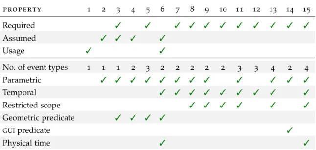
Out of all the properties I gathered as relevant, I extracted a shorter list of 15 properties that were deemed representative, based on the temporal relationships featured between events, the type of event data, and the operations performed on event data. tka properties are now listed in arbitrary order.
Property 1. The trace contains a step “redo acquisitions”.
The “redo acquisition” step allows the surgeon to correct his previ-ous acquisition. It is not part of the standard procedure flow and, therefore, interesting to detect.
Property 2. The temperature of the camera stays within a given interval. If used in proper conditions, the camera temperature should not de-viate from the range where its precision is guaranteed.
Property 3. The distance between pairs of hip centers is less than d. This property asserts that the algorithm computing the hip center is stable, i.e. gives similar results for consecutive acquisitions.
Property 4. The distance between the hip center and the knee center is greater than d.
A violation of this property could reveal an abnormal positioning of the patient or the sensors.
Property 5. If the medial malleolus is farther from the camera than the lateral one, a warning is issued.
A violation of this property may reveal that the 3D camera was in-stalled on the wrong side of the patient.
Property 6. The user never skips a screen.
The surgeon is expected to spend sufficient time to appreciate the information showed on the display before going to the next screen. Property 7. The acquisition of a point succeeds if and only if the probe is stable.
If the surgeon moves the probe tip during an acquisition, it should not be accepted.
Property 8. The protocol “redo acquisitions” only proposes already per-formed acquisitions.
The system should not offer the user to redo acquisitions that were never performed.
Property 9. Detecting a new tracker produces a dialog asking for replace-ment confirmation.
Property 10. The state TrackersConnection is unreachable until the camera is connected.
The system should not reach a state dependent on the camera until the camera is connected.
Property 11. A replaced tracker is not used until it is registered again. Property 12. The action “previous” cancels the current point cloud acqui-sition.
Acquiring a cloud of points takes a few seconds and can be cancelled. In this case, the current acquisition should not succeed.
Property 13. All the necessary trackers are seen before entering the state TrackersVisibCheck.
To proceed, the system requires a set of trackers depending on the profile in use. All these trackers should be seen at least once before entering the state TrackersVisibCheck.
Property 14. On the tracker connection screen, a tracker is shown if and only if it is necessary.
Only required trackers are shown to the user.
Property 15. In the state TrackersConnection, not detecting a single tracker for 2 minutes produces an error message.
3.3 t y p e s o f p r o p e r t i e s a n d t h e i r u s e
Trace properties are very versatile in the analysis of medical device executions. They can be used to encode the requirements of a system, but also to detect specific behaviors of the system. In this section, we propose a classification for trace properties for medical devices according to three categories: required, assumed and usage properties. r e q u i r e d p r o p e r t i e s Required properties must be ensured by the system, and more precisely by its software. tka properties cor-respond to requirements on the software. For instance, one of the requirements of the TKA software states that it should check the sta-bility of the probe before validating the acquisition of a point. It can be restated as a required property: “The acquisition of a point succeeds if and only if the probe is stable”.
Checking these properties on the traces should always succeed, oth-erwise it would reveal a failure of the software. Ideally, these prop-erties should be formally proven. This is why we refer to these as required properties. In the medical device industry, a more pragmatic approach is to provide verified traces as evidences that they are ful-filled by the product, and not full proofs.
3.3 types of properties and their use 27
a s s u m e d p r o p e r t i e s Assumed properties should be ensured by the environment of a system. They appear as assumptions on the behavior of this environment. If the environment fails to fulfill these properties, the behavior of the system may be affected. In the context of TKA, the property “The temperature of the camera stays within a given interval” is an example of assumed property. If the temperature is outside this range, the precision of the camera may be affected. Violations of assumed properties by the environment may or may not be detectable by the software. When the environment does not behave as expected, or is suspected not to, the desired response from the software is not obvious. In such a situation, TKA is designed to not stop assisting the surgery so that the surgeon remains in control, but it repetitively displays modal warnings.
Checking these properties on traces is expected to succeed because the surgeon and his team are expected to use the system in the pre-scribed conditions. If one of these properties is not satisfied, it may be an explanation for difficulties arising during the surgery and it does not necessarily reveal a defect of the system. tka assumptions on the behavior of the environment will be referred to as assumed properties. Note that properties can be both required and assumed. This happens for properties whose satisfaction depends on the environment and the software implementation. For instance, consider theTKAproperty “The distance between pairs of hip centers is less than d”. It can result from the use of a leg holder, which violates assumptions on the environ-ment, or from a wrong calculation which reveals a software failure. Since the trace does not record that a leg holder was used, a violation of this property leaves two possible causes.
u s a g e p r o p e r t i e s Some medical devices such as TKA may offer different workflows, depending on the precise nature of the inter-vention and on the surgeon’s choices. Properties can be checked to understand how the system was used.
For example, this is the case of the property “The trace contains a step ‘redo acquisitions’”. The “redo acquisition” step is triggered by the
sur-geon and may reveal that it is difficult to have all acquisitions right at the first attempt, or that the surgeon is not trained enough to use the system. Checking these properties helps understand the way a sys-tem is used, but does not reveal a particular failure of the syssys-tem or its environment. It can be exploited to identify potential evolutions of the system (e.g. efforts should be done to facilitate acquisitions). This is why we refer to such properties as usage properties.
Statistics can be computed on the number of traces satisfying a given usage property. At longer term, “quantitative usage properties” might be considered, reporting quantities instead of Boolean values