Publisher’s version / Version de l'éditeur:
Construction Technology Update, 2000-12-01
READ THESE TERMS AND CONDITIONS CAREFULLY BEFORE USING THIS WEBSITE. https://nrc-publications.canada.ca/eng/copyright
Vous avez des questions? Nous pouvons vous aider. Pour communiquer directement avec un auteur, consultez la
première page de la revue dans laquelle son article a été publié afin de trouver ses coordonnées. Si vous n’arrivez pas à les repérer, communiquez avec nous à [email protected].
Questions? Contact the NRC Publications Archive team at
[email protected]. If you wish to email the authors directly, please see the first page of the publication for their contact information.
NRC Publications Archive
Archives des publications du CNRC
For the publisher’s version, please access the DOI link below./ Pour consulter la version de l’éditeur, utilisez le lien DOI ci-dessous.
https://doi.org/10.4224/20326709
Access and use of this website and the material on it are subject to the Terms and Conditions set forth at
A method for evaluating air barrier systems and materials
Di Lenardo, B.
https://publications-cnrc.canada.ca/fra/droits
L’accès à ce site Web et l’utilisation de son contenu sont assujettis aux conditions présentées dans le site LISEZ CES CONDITIONS ATTENTIVEMENT AVANT D’UTILISER CE SITE WEB.
NRC Publications Record / Notice d'Archives des publications de CNRC:
https://nrc-publications.canada.ca/eng/view/object/?id=bb4006a0-262a-4dcd-aa52-7c70e620ccdc https://publications-cnrc.canada.ca/fra/voir/objet/?id=bb4006a0-262a-4dcd-aa52-7c70e620ccdcC o n s t r u c t i o n T e c h n o l o g y U p d a t e N o . 4 6
The air barrier system is an essential element in the performance of building envelopes. Its role in the control of air, heat and moisture movement across the building envelope was identified by the Institute for Research in Construction (IRC) more than 30 years ago.
Many performance and deterioration problems of building envelopes can be attributed to inadequate or failed air barrier systems. Although the importance of the air barrier system has been known for decades, the characteristics that it must have to perform adequately have not been clear. Recent research has allowed for the development of a test method that enables its performance to be evaluated.
1995 National Building Code Requirements
The National Building Code (NBC) defines the air barrier system as an assembly of materials installed in the building envelope to provide a continuous barrier to the movement of air. As well as being continuous, the effectiveness of the air barrier system depends on its
• air permeance
• structural strength and rigidity • durability
• buildability.
In order to constitute a ‘system’ the com-ponents of the air barrier system must be joined to each other to provide the required continuity and structural sufficiency.
The NBC requirements for the air barrier system address the control of heat, air and moisture transfer through the building envelope. Failure to achieve such control can have adverse effects on building enve-lope components, assemblies and equip-ment, and can lead to health and safety risks for occupants stemming from struc-tural damage, compromised operation of building services and life safety systems, and air quality problems.
NBC Part 9 Housing and Small Buildings Part 9 of the NBC covers houses and small buildings. The only requirement for these buildings is that the air barrier system provide “an effective barrier to air exfiltration under differential air pressure due to stack effect, mechanical systems and wind.”
by Bruno Di Lenardo
This Update explains the purpose and characteristics of the air barrier system
in the building envelope as defined by the National Building Code of Canada.
It discusses the code requirements for these systems and explains the role of the
Canadian Construction Material Centre’s evaluation criteria in determining
whether a system meets these requirements.
A Method for Evaluating
Air Barrier Systems
and Materials
Since air leakage can be a significant heat transfer mechanism, the Model National Energy Codes of Canada also have require-ments related to the air leakage of the whole building and, indirectly, the perform-ance of the air barrier system.1
2
Part 9 does not contain quantitative require-ments for allowable air leakage of either an air barrier system or the materials used to form it, or for its structural capacity and durability.
Table A-9.25.1.2.B in the NBC lists materials with air leakage rates low enough to act as the principal component of the air barrier system. For many buildings within the scope of Part 9 it is common to use a 6-mil polyethylene sheet located on the warm side of the wall as the vapour barrier. The polyethylene can also be configured to serve as the air barrier material, as long as the required continuity and structural sufficiency is provided by the system. However, the air barrier system does not necessarily have to be located toward the warm side of the assembly. If it has low water-vapour permeance and is located on the cold side of the assembly, there is an increased risk of condensation on its surface. Under these circumstances, the location of the air barrier system relative to the thermal barrier is critical. (See Construction Technology Update No. 41, Low-Permeance Materials in Building Envelopes).
NBC Part 5 Environmental Separation Part 5 of the NBC covers buildings that fall outside the scope of Part 9. Specifically, it addresses the requirements for the assem-blies and components that separate dissimi-lar environments (e.g., inside and outside) in these buildings. This part of the code more clearly characterizes an effective air barrier system:
• its materials must be adequately airtight; • it must be continuous throughout the
building envelope;
• it must be strong enough to resist air pressure loads without undue deflection and be designed to transfer these loads to the building structure;
• it must be sufficiently durable to perform for the design service life.
Part 5 stipulates that sheet- and panel-type materials that provide the “principal resistance to air leakage” must have an air leakage rate not exceeding 0.02 L/(s•m2) at 75 Pa pressure difference. The prescribed test pressure of 75 Pa is used to characterize a material property and is not intended to represent typical pressures experienced by the material in situ.
To comply with Part 5, the structural capacity of the air barrier system must be sufficient to resist 100% of the wind load for which the wall or roof structure is designed (as determined in Part 4, Structural Design), and it must be supported and attached so that this load can be transferred to the structure. As well, deflections must not affect the non-structural elements of the wall assembly when the air barrier system is subjected to wind loads of 1.5 times the specified wind load.
The air barrier system must be able to resist and transfer the full wind pressure to the building structure without damage to itself (or to other components of the wall assembly). However, the airtight material does not need to rely on its own strength to resist these structural loads. It can be supported by another material, or framing, of adequate strength and rigidity that is considered to be part of the system. In the case of a propri-etary air barrier system (i.e., a system man-ufactured and sold by a particular firm) both the airtight component and the structural components of the system, such as substrates and fastenings, must be identified and included in the evaluation of the system.
Part 5 also requires that all materials used in the building envelope, including those in the air barrier system, be compatible with adjoining materials and resistant to deterioration under the expected environ-mental loads for the intended use and geographic location.
There are no prescriptive requirements or criteria for achieving continuity in Part 5. In the case of proprietary air barrier systems, it is usually the responsibility of the proponent to demonstrate how the air barrier will bridge joints, seal penetrations and connect to other components such as windows, doors, walls and roofs.
The committee responsible for Part 5 of the NBC recognized that, ideally, the maximum air leakage rate of the complete air barrier system (including materials and joints) should be specified. However, at the time the 1995 NBC was finalized, there was insufficient knowledge of the performance of the air barrier system to permit this rate to be specified. Thus only a ‘material’ air leakage rate was specified, making it difficult to evaluate systems. The subsequent development of the CCMC technical guide for the evaluation of air barrier systems
(see below) addressed this limitation. Table A-5.4.1.2 of the NBC provides a list of recommended maximum system air leakage rates suitable for Canadian climates.2 CCMC Technical Guide for
Evaluation of Air Barrier Systems While Part 5 stipulates performance
requirements for the air barrier system, there has been no standard procedure to assess whether an assembly of materials meets the NBC requirements. This meant that when a non-standard approach to air leakage was proposed, there was no way to evaluate it.
At the request of industry,3the Canadian Construction Materials Centre (CCMC) initiated a program to gain a better under-standing of the fundamental performance requirements of an air barrier system and develop a method for evaluating the
effectiveness and durability of such systems. As part of this process, CCMC determined acceptance criteria and identified test procedures to establish whether a propri-etary system meets the intent of the code. The work resulted in a technical guide (see box on “CCMC Evaluation Process”), which could provide the basis for a CGSB standard.
The technical guide provides requirements, methods and criteria for evaluating the per-formance of proprietary air barrier systems for walls of low-rise buildings (up to three
storeys high). Its technical criteria address the air barrier system’s air leakage test char-acteristics (in the form of a test protocol for verifying compliance to the air leakage rate requirement stipulated in Part 5 of the NBC), its structural capacity, continuity, durability and buildability.
Development of Technical Guide
In developing the technical guide, CCMC determined acceptable air leakage rates for various climatic conditions and wall config-urations. These air leakage rates were established through a computer modelling program carried out by IRC researchers in conjunction with the Technical Research Center (VTT) in Finland. Next, a test procedure to measure the air leakage rate of air barrier systems was developed. This test procedure was then used to establish the air leakage rating of a system at the standard reference pressure of 75 Pa.
The model took into consideration the interrelationships of heat transfer, air movement, moisture diffusion and airborne moisture transport using real weather data. It was also able to account for the impact of changes to the configuration of a building assembly or the properties of the building components on the accumulation of moisture within the assembly. Interior relative humidities greater than 35% were not considered (such humidity levels constitute “special design”). The researchers
CCMC Evaluation Process
Section 2.5, Equivalents, of the National Building Code permits the use of products, systems and methods not specifically mentioned in the code or the standards it references if it can be shown to the satisfaction of the authority having jurisdiction that the product, system or method meets the intent of the code. This can be problematic for proponents of innovative products since (a) it can often be difficult to determine exactly what the intent of the code is and (b) there are a large number of authorities having jurisdiction in Canada that must be satisfied and they may apply different criteria.
One of the services offered by IRC’s Canadian Construction Material Centre (CCMC) is the evaluation of inno-vative products to determine whether they meet the intent of the code and, if so, under what circumstances and limitations. These evaluations constitute advice from a credible source on which local building officials can base their decisions regarding a product, system or method without usurping the official’s authority in making final decisions. CCMC evaluations are widely accepted by municipal and provincial building offi-cials in all parts of Canada.
CCMC evaluations are based on technical guides (evaluation guidelines) that are drawn up in consultation with expert advisors, including staff from IRC’s Canadian Codes Centre and research programs. Both groups play an important role in establishing code equivalency. These technical guides are in effect non-consensus standards; their advantage is that they can be developed much more rapidly than is normally possible with the usual process adhered to in the development of consensus documents such as building codes and standards. If the innova-tive product is successful and the industry wishes to pursue a consensus standard, the CCMC technical guide is offered to the appropriate standards development organization as an initial draft.
used this model to simulate various combi-nations of the overall air leakage rate of the wall and the water-vapour permeance of the outermost layer of the wall for the climates of Edmonton, Ottawa and Halifax.
Permissible air leakage rates
The maximum permissible air leakage rates (presented in Table 1) established through the modelling program and test procedure are based on two main considerations: 1. Moisture can be transported by air leakage
and condense within the building envelope assembly.
2. The accumulation of condensation is related to, among other factors, the drying potential of the wall assembly, which is in turn influenced by the water-vapour permeance of the outermost layer.
These air leakage rates are included in the CCMC technical guide, and provide the criteria that have to be met by an air barrier system submitted for evaluation.
Evaluation Process
The CCMC technical guide requires that three full-scale (2.4 m x 2.4 m) wall test specimens be evaluated in a particular sequence. The specimens are constructed according to the installation instructions provided by the system proponent to represent the field situation since the way a system is built can affect its continuity, durability and performance.
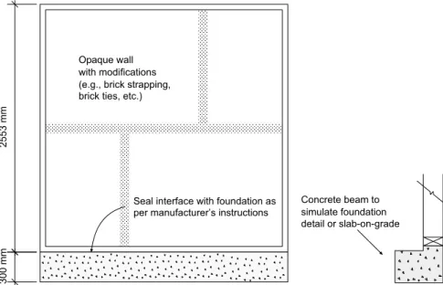
Specimen 1 represents the air barrier system within the opaque, insulated portion of the wall. Specimens 2 and 3 contain penetrations and joints and are used to verify the continuity of the system (e.g., at window, pipe, duct, concrete sill locations) sealed by the accessories that are part of the air barrier system (see Figures 1, 2 and 3).
Structural testing and requirements
All test specimens are aged structurally prior to air leakage testing. To evaluate their structural capacity, they are subjected to positive and negative pressures consisting of a one-hour sustained load, 2000 cyclic loads and one gust wind load (Figure 4). The wind loading follows a specific schedule with test pressures and cycles representative of the effects of the two or three major storms likely to be experienced by a building during its service life. The test pressures (P1, P2and P3) are determined by factoring (to account for sustained wind load, gust load and cyclic load) the (highest)
4 Construction Technology Update No. 46
Figure 1. Specimen 1. Opaque wall specimen used to
obtain air leakage data
Figure 2. Specimen 2. Wall specimen with penetrations
through the air barrier system to demonstrate continuity of system at penetrations
Table 1. Maximum Permissible Air Leakage Rates — Air Barrier System
Water-Vapour Permeance (WVP) of Maximum Permissible Outermost Uninsulated (Non-Vented) Air Leakage Rates4
Layer of the Wall Assembly L/(s•m2) at 75 Pa ng/(Pa•s•m2)
15 < WVP ≤60 0.05 60 < WVP ≤170 0.10 170 < WVP ≤800 0.15
hourly wind pressure that would be
exceeded only once in 10 years for the area where the system will be marketed.
In addition, the deflection of the air barrier system at 150 percent of the design wind pressure (specified in Part 5 of the NBC) is recorded in this test because it is considered useful information for designers.
Air leakage rate testing and requirements
After structural testing, the air leakage of the three specimens is measured at a number of pressure differ-ences and the air leakage rate at 75 Pa determined by fitting a straight line through the data points. This air leakage rate for the system is considered to have satis-fied the CCMC criteria only if the leakage of Specimen 1 is less than the relevant value in Table 1 and Specimens 2 and 3 are no more than 10% leakier than the opaque specimen (Specimen 1). This requirement takes into account the fact that it is more difficult for an assem-bly with joints to be con-structed with the same degree of airtightness as one without joints.
Durability testing and requirements
In addition to developing air leakage and structural criteria, a durability proto-col was established. The durability of an air barrier system depends on its compatibility with adjacent materials and the environ-mental loads to which it is subjected over its service life. The CCMC protocol takes into account such issues as exposure to ultraviolet light (UV) during construction and deterioration from aging. The climatic factors that affect durability include temperature, moisture, solar radiation, electrochemical factors, and biological agents. The service life of an assembly can be extended if it is possible to carry out repairs in an economical fashion, which usually depends on the accessibility of the air barrier system. Most air barrier systems, however, are not readily accessible.
Figure 3. Specimen 3. Wall specimen with connections to other building
elements to demonstrate continuity of air barrier system at interface (e.g., opaque wall with foundation)
“Construction Technology Updates” is a series of technical articles containing practical information distilled from recent construction research.
For more information, contact Institute for Research in Construction, National Research Council of Canada, Ottawa K1A 0R6
Telephone: (613) 993-2607; Facsimile: (613) 952-7673; Internet: http://irc.nrc-cnrc.gc.ca © 2000
National Research Council of Canada December 2000
ISSN 1206-1220
There is no universal durability protocol that applies to all possible materials or combinations of materials. Hence, the CCMC evaluation of the durability of mate-rials used in an air barrier system is made on a case-by-case basis. Using accelerated-aging tests to determine UV degradation and heat aging, acceptance criteria for air barrier materials that form the principal plane of airtightness have been established. These criteria are based on retention of 85% of the original strength and an increase of no more than 10% in air permeance.
Other requirements
The specimen tests are only one part of the evaluation process. In addition, CCMC reviews the proponent’s quality assurance program, obtains material samples from the manufacturing facility, considers the delivery system to the field (supply and installation), and ensures that the test specimens are prepared as they would be in the field. All aspects of the system are assessed relative to the criteria established in the technical guide.
CCMC then writes an evaluation report, which includes limitations on the use of the product — for example, the maximum acceptable interior humidity level for which the product can be used. As well, the report stipulates necessary system details such as the components and accessories, installation tolerances and other features to ensure that construction in the field replicates the evaluated system. Conclusion
Experience has shown that an effective air barrier system is essential to achieve acceptable performance in modern buildings. Quantification of the characteristics these systems must have plus CCMC’s development of an appropriate test procedure means that manufacturers, designers and builders can now determine whether an air barrier system meets the requirements of the 1995 National Building Code.
Further Information
For more information on the development of the CCMC test protocol and evaluation criteria, see IRC’s publication Air Barrier
Systems for Walls of Low-Rise Buildings: Performance and Assessment. The
publica-tion also discusses the intent of the NBC requirements and the relationship between the vapour barrier and the air barrier system. For CCMC evaluations of specific air barrier materials and proprietary systems, consult CCMC’s Registry of Product Evaluations. Footnotes
1. It is important to note the difference between whole-building airtightness tests and the permissible air leakage rates measured by the CCMC technical guide tests. Whole-building airtightness tests include the air leakage through windows and doors and are normally conducted in tandem with estimates of energy loss. The air leakage rate evaluated by the CCMC technical guide is the leakage through the opaque, insulated portion of the wall, as intended by the NBC.
2. These air leakage rates were first suggested in the Institute for Research in Construction (IRC) Building Science Insight ’86, “An Air Barrier for the Building Envelope.”
3. This work was funded by a consortium of manufacturers, NRC’s Industrial Research Assistance Program (IRAP) (through the Canadian Home Builders’ Association), and the Canadian Codes Centre.
4. These air leakage rates were determined with a 60 ng/(Pa•s•m2) vapour barrier on the warm side
and interior conditions of 21°C and 35% RH.
Bruno Di Lenardo is an evaluation officer with
the Canadian Construction Materials Centre (CCMC) of the National Research Council’s Institute for Research in Construction.