HAL Id: hal-01709736
https://hal-univ-rennes1.archives-ouvertes.fr/hal-01709736
Submitted on 27 Apr 2018HAL is a multi-disciplinary open access
archive for the deposit and dissemination of sci-entific research documents, whether they are pub-lished or not. The documents may come from teaching and research institutions in France or abroad, or from public or private research centers.
L’archive ouverte pluridisciplinaire HAL, est destinée au dépôt et à la diffusion de documents scientifiques de niveau recherche, publiés ou non, émanant des établissements d’enseignement et de recherche français ou étrangers, des laboratoires publics ou privés.
Localized atomic segregation in the spalled area of a
Zr50Cu40Al10 bulk metallic glasses induced by
laser-shock experiment
B. Jodar, D. Loison, Y. Yokoyama, E. Lescoute, M. Nivard, L. Berthe,
Jean-Christophe Sangleboeuf
To cite this version:
B. Jodar, D. Loison, Y. Yokoyama, E. Lescoute, M. Nivard, et al.. Localized atomic segregation in the spalled area of a Zr50Cu40Al10 bulk metallic glasses induced by laser-shock experiment. Journal of Physics D: Applied Physics, IOP Publishing, 2018, 51 (6), pp.065304. �10.1088/1361-6463/aaa322�. �hal-01709736�
Localized Atomic Segregation in the Spalled Area of a
Zr
50Cu
40Al
10Bulk Metallic Glasses Induced by Laser-shock
Experiment.
B. Jodar,1, ∗ D. Loison,1, † Y. Yokoyama,2 E. Lescoute,3
M. Nivard,1 L. Berthe,4 and J.-C. Sangleboeuf1
1Institute of Physics Rennes, UMR CNRS 6251, Rennes, France. 2Institute for Material Research, Tohoku University, Sendai, Japan.
3CEA/DAM/DIF, Arpajon, France. 4PIMM, UMR CNRS 8006, Paris, France
Abstract
Abstract. Laser-shock experiments were performed on a ternary Zr50Cu40Al10Bulk Metallic Glass. Spalling process was studied through post-mortem analyses conducted on recovered sample and spall. Scanning Electron Microscopy magnification of fracture surfaces revealed the presence of a peculiar feature known as cup-cone. Cups are found on sample fracture surface while cones are observed on spall. Two distinct regions can be observed on cups and cones: a smooth viscous-like in the center and a flat one with large vein-pattern in periphery. Energie Dispersive Spectroscopy measurements conducted on these features emphasized atomic distribution discrepancies both on sample and spall. We propose a mechanism for the initiation and the growth of these features but also a process for atomic segregation during spallation. Cup and cones would originate from cracks arising from shear bands formation (softened paths). These shear bands result from a quadrupolar-shaped atomic disorder engendered around an initiation site by shock wave propagation. This disorder turns into shear band when tensile front reaches spallation plane. During the separation process, temperature gain induced by shock wave and shear bands generation decreases material viscosity leading to higher atomic mobility. Once in a liquid-like form, atomic clusters migrate and segregate due to inertial effects originating from particle velocity variation (interaction of release waves). As a result, a high rate of copper is found in sample cups and high zirconium concentration is found on spall cones.
∗ Corresponding author: benjamin.jodar@univ-rennes1.fr † Additionnal contact: didier.loison@univ-rennes1.fr
I. INTRODUCTION
Unique and intriguing properties of amorphous alloys have nourished several scientific minds during the past decades. Since their discovery in 1960 by Klement et al[1] and their development in bulk glass-form[2], extensive works have been provided on their synthesis, glass forming ability and structure design[3] related to various icosahedral configurations distributions into an amorphous medium depending on the composition. Regarding the mechanical behavior, substantial studies were reported on deformation mechanisms based mostly on the free volume and Shear Transformation Zone (STZ) theories. Cao et al [22] used molecular dynamics to correlate the evolution of icosahedral structures under quasi-static loading conditions of a binary Cu-Zr Bulk Metallic Glass (BMG) to the localized shear flow process. Maas et al studied experimentally at low strain rates (10−3s−1) the influence of temperature on the shear bands propagation [23] and velocity [24] to determine how the local structure, that is very temperature sensitive, governs the shear band formation and propagation. Thurneer et al [25] performed compression at strain rate between 10−4s−1 and 10−3 s−1 experiments on several compositions of a ternary ZrCuAl BMG at various sub-ambient temperatures to measure the activation energy for shear band propagation and determine how it is linked to atomic bonding.
In contrast, only few studies were published on the dynamic behavior of BMG. Few equations of states (EOS) and Hugoniot curves were reported by Martin et al on a Zr57N b5Cu15.4N i12.6Al10 using single and bi-stage gas guns for pressures up to 122 GP a
[8], by Togo et al on a Zr55Al10N i5Cu30 also by plate-impact experiments for pressure
range lower than 45 GP a [9] and Xi et al on a Zr51T i5N i10Cu25Al9 up to 110 GP a [10].
From these studies, BMG revealed several phases transitions that are composition depen-dent. The dynamic elasto-plastic transition was previously studied by Turneaure et al on a Zr56.7Cu15.3N i12.5N b5.0Al10.0Y0.5 [11, 12] were the Hugoniot Elastic Limit (HEL) was
measured to be around 7 GP a. The shock wave instability related to pressure just above the HEL highlighted a strain-softening response that is well known in static to be a char-acteristic response upon loadings exceeding the elastic domain. Smirnov et al and Luo et al also reported the HEL of a Zr55AlN iCu [14] and a Zr51T i5N i10Cu25Al9 [15] BMGs
respectively to be around 4.5 GP a and 8.9 GP a. Arman et al used molecular dynamic simulations to follow the evolution of icosahedral structures on a binary Cu46Zr54 BMG
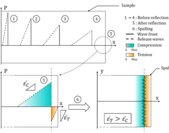
FIG. 1. Illustration of a shock wave propagation. Once generated, shock waves induced by laser become triangular (1). During propagation, release waves spread and peak pressure decays with travelled distance (1)→(4). Behind shock front, motion is provided to matter. When arriving at free-surface, shock wave turns into releases waves and pressure drops by the interaction of incident and reflected release waves. Subsequent strain and stress states are no longer compressed but tensed, directly impacting strain rate and inducing loading asymmetry within specimen. Matter separation (spalling) occurs when the dynamic tensile threshold of the material is reached, resulting in the ejection of matter (spall) (6).
for pressures range around the elasto-plastic transition to determine how some icosahedral configurations contribute to strain-softening [13] The dynamic tensile limits with strain rate in range of 104 s−1 to 106 s−1 were also reported to be in range of 2 − 4 GP a by several authors [16, 18, 19] for various Zr-based BMG depending on the compositions. Spalling process induced by planar shock and resulting fracture surfaces were also studied. Zhuang et al [16] and Yang et al [17] performed Scanning Electron Microscopy on recovered target that showed shear band on the cross section and vein-pattern on the fracture surface. Light emission was observed by Sun et al during spallation [20]. Escobedo et al [19] and Lu et al [21] also reported vein-pattern on fracture surface that also contained cup-cones formations.
For decades, laser-shock has been used to study spallation in metals [26–28] and glass [29] but also to study the mixed-mod shock wave loading at high strain rate on polymers [30]. Loadings induced by nanoseconds laser plasma can be reached up to 102 GP a with high strain rate (106 to 109 s−1). This technique with soft low density gel (∼ 0.9 g.cm−3)
allows sample and spall recovery for post-mortem analysis [31].The generated loading shape is triangular (1) as illustrated in Fig. 1. When reaching the rear surface, the shock wave is reflected into a release wave (5). The meeting of the incident and reflected releases engenders an inverted pressure front. Ahead of this front, the specimen is still under compression, while tension is observed behind (close to the free surface). It is essential to notice that the strain rate in compression differs from the one in tension, due to release waves spread. Once the dynamic tensile threshold of the material is reached, spallation occurs, leading to matter separation and ejection (6). Finally, to avoid edge effects in laser shock induced spallation, thin samples are machined to ensure uniaxial strain state.
In this paper, we study spallation at high strain rates and high pressures of a Zr50Cu40Al10
BMG using shock produced by laser. Especially, this paper deals with the formation of cup-cone features observed on recovered sample and spall. A discussion focuses on atomic segregation phenomena observed in fracture areas. First part introduces the experimental setup and methods. The second part reports post-mortem observations and measurements. In the last part, results are discussed.
II. EXPERIMENTAL SETUP
A single master ingot of ternary Zr50Cu40Al10 BMG was prepared by arc-melting
mix-tures of high purity Zr, Cu and Al under an argon atmosphere. The Zr crystal rod used here contains an oxygen concentration less than 0.05 atomic percent to avoid crystallization during casting process. The master ingot was cast using the tilt-casting method [32] into a 10 mm diameter rod and 45 mm long. As reported by Yokoyama et al [32], this technique reduces the formation of cold shuts that act as crack-initiation sites. According to initial properties, the density of the Zr50Cu40Al10 BMG rod was measured by the Archimedes
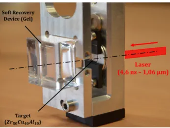
method using purified water and was found to be 6.809 ± 0.006 g.cm−3. The cast structure was also controlled by Optical Microscopy (OM) and Scanning Electron Microscopy (SEM) and the phase was characterized by X-ray diffractometry exhibiting no Bragg peaks of any crystalline phase. The ultrasonic echography technique was used to obtain Poisson ratios, Young’s and shear modulus which were found to be correspondingly equal to 0.369 ± 0.02, 89.3 ± 1 GP a and 32.6 ± 1 GP a. The final target was cut from this single master ingot and polished into a 215 µm thickness slice with a 1 µm flatness controlled by confocal
FIG. 2. Photography of the sample holder with the soft recovery device used for collecting ejectas. The complete system is set in a secondary vacuum chamber (10−3 P a is achieved) to avoid laser breakdown with air. In this situation, laser is irradiating the front face of the sample (not visible here) from the right.
profilometry.
Laser shock experiments were performed on the LULI2000 facility (UMR 7605, Ecole Polytechnique, Palaiseau, France). Laser provides a 4.6 ns duration high power square pulse at 1.06 µm-wavelength focused onto the specimen surface (spot diameter of 2.9 mm). Samples are set in a secondary vacuum chamber (10−3 P a is achieved) to avoid laser break-down with air. Provided energy is 800 J maximum resulting in laser intensities up to 2.60 T W .cm−2. Spalls ejected from target free-surface were collected into a soft recovery device. The experimental setup is displayed in Fig. 2. Post-mortem observations and analysis were performed on recovered fracture surfaces both on sample and spall by a Scanning Elec-tron Microscopy (SEM) and atomic content was probed by Energy Dispersive Spectroscopy (EDS) on the ScanMat facility (UMS 2001, Rennes, France). Atomic distribution profiles were established in several positions, i.e. in the form of measurements lines made of 200 points with a spatial resolution of 1 µm3 for each points, to follow the evolution of atomic distribution according to position in cup and cones.
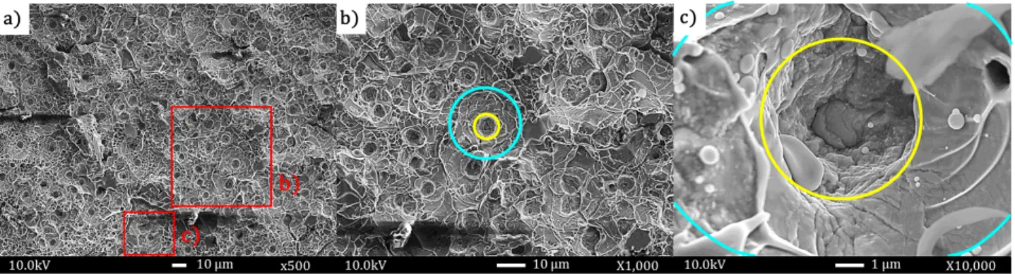
FIG. 3. SEM pictures of recovered sample. Magnifications in picture (a) (squares in red line) reveal a complex fracture surface with cups. Pictures (b) and (c) exhibit two distinct areas on cups: a smooth central area (yellow circle) and a flat outlying one (blue circle). On magnification (c) melted droplets can be distinguished.
III. RESULTS
In the Fig. 3 are displayed the typical central spalled area of a 215 µm thick sample (a) irradiated by a 2.45 T W .cm−2 intensity equivalent to a ∼ 60 GP a pressure obtained by laser-matter interaction simulations using one dimensional Lagrangian code ESTHER [33]. Its corresponding recovered spall is showed in Fig. 4 (a). First, one may distin-guish on both surfaces the presence of multiple objects, referred as cup-cones. Several authors also reported such characteristic pattern in case of plate-impact experiments [19] in a Zr56.7Cu15.3N i12.5N b5.0Al10.0Y0.5 and [21] in a Zr50Cu40Al10 BMG. Main differences
between these studies and present one regard the number, the size, the morphologies but also the location of cup-cones on spall or sample. Reported cup-cones diameters were on average ten times larger and ten time less numerous for a same area than the one showed here. Lu et al [21] reported smoother cup and cones surfaces. Recovered spall and sample surfaces differ one another respectively from the presence of cups on sample and cones on spall. However, in previous studies spalls were not recovered so that direct confrontation is not possible.
At cup-cones scale, cups emphasize a smooth and viscous-like central region (Fig. 3 (b) and (c), circles in yellow lines). Flat peripheral rings with large vein-pattern can be distinguished (Fig. 3 (b) and (c), circles in blue lines). This vein-pattern is usually observed on fracture surfaces in metallic glasses and results from instabilities in the liquid-like layer
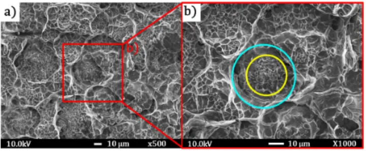
FIG. 4. SEM images of recovered spall. Fracture surface is here made of multiple cones (a). Magnification of image (a) (red square) also emphasizes in picture (b) two distinct regions on cones (similarly to cups). The smooth central area is depicted by the yellow circle and the flat area by the blue circle.
that forms during shear banding [5]. Small molten droplets can also be observed (Fig. 3 (c)) mostly in the outlying region, suggesting viscosity drop (or melting). On the contrary, cones appear clearly grainier in the central area (Fig. 4 (b), yellow circle) with fewer or no droplets. The characteristic vein pattern is here thinner than observed on cups central area. Outlying rings with large vein-patterns are sometimes observed on the bottom of cones (Fig. 4 (b), blue circle). According to Deibler et al [34], these various vein pattern sizes can be attributed to a viscosity discrepancy, where a large pattern is synonym of low viscosity, and thin pattern size to high viscosity. This apparent viscosity difference may be explained by Pampillo work [35] that provided evidences of structural disordering effect within shear bands. Most specifically, it suggested that chemical potential may be altered relatively to the bulk within the bands. In addition, it was reported by Leamy et al [36] that the flow and fracture surface process of metallic glasses in quasi-static tension show a smooth and a veined regions, similar to the two distinct areas observed both in cups and cones.
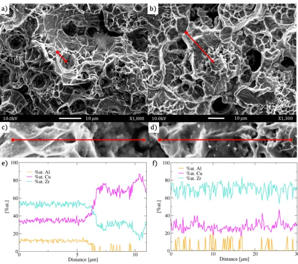
At atomic scale, EDS measurements on surfaces of cups (Fig. 5 (a) - red line) and cones (Fig. 5 (b) - red line) revealed atomic composition discrepancies in comparison with original one (Zr: 50%, Cu: 40%, Al: 10%). Altogether, 50 cups and 50 cones were probed. According to position, atomic distribution in cups (Fig. 5 (e)) and cones (Fig. 5 (f)) varies strongly. By taking account of EDS accuracy (±5%), cups appear rich in copper (Zr: ∼25%, Cu: ∼70%, Al: ∼5%) while cones are rich in zirconium (Zr: ∼70%, Cu: ∼25%, Al: ∼5%). Once outside of these features, atomic content tend to the initial rate, as depicted by Fig. 5 (e).
FIG. 5. EDS measurements of atomic distribution on cup-cones fracture surface. SEM magni-fications of sample cups (a) cones on recovered spall (b) with the probed positions (red lines). Magnifications of probed cup and cone are depicted by red lines in (c) and (d) respectively. The atomic distribution of Zr, Cu and Al depending on the position is displayed for a cup (e) and a cone (f). Cups seem to be rich in copper and poor in zirconium. Its the opposite for cones that are rich in Zr and lack of Cu. Aluminum content remains approximatively constant. Outside of the cup-cone feature, the initial composition rate is found.
IV. DISCUSSION
In metallic glasses, several studies with quasi-static loadings have provided key elements relative to its plasticity and were regrouped as a deformation map proposed by Schuh et al [4]. It is now well established that metallic glasses exhibit two regimes of plastic flows: homogeneous at high temperature and low strain rate, inhomogeneous at room temperature and high strain rate that is associated with shear bands. In this last domain, plasticity and
yielding are controlled by the initiation, the propagation and the evolution of shear bands that usually lead to failure.
In the present study, i.e. in a dynamic loading situation, strain rate is very high and temperature remains an opened question. Nonetheless, according to shock wave nature (that is strongly discontinuous), it is presumably reasonable to consider that plastic flow under shock is inhomogeneous. This in mind, initiation and propagation of cup-cones correlated with a process for atomic segregation will be discussed according to the shock wave theory but also results reported by quasi-static studies on metallic glasses.
A. Cup-Cone initiation and propagation
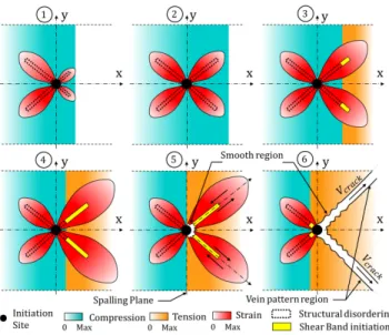
If one considers a peculiar site from which plasticity can be initiated Fig. 6 (1), when the shock wave (schematized by the blue front traveling from left to right) interacts with this site, a surrounding displacement field is induced. This local atomic displacement is larger than the one of the surrounding matrix leading to local shearing. This region of local atomic displacement and shearing has been referred in the literature as Shear Transformation [37] or Shear Transformation Zone (STZ) [38] and is assumed to be responsible for plasticity triggering. Experimental [39] and numerical [40] studies emphasized the quadrupolar char-acter of the created strain field (red areas in Fig. 6) which decays with the distance from the STZ center to the surrounding matrix (Fig. 6 (1)). Greer et al [5] proposed a two-stage scenario for shear band initiation. Once a STZ is activated (first stage) the atomic structure is disordered and atoms gain mobility.
At that point, shear strain is small and temperature raise not substantial. Hence, it forms a softened path for sliding and shear to concentrate (second stage). Since matter is softened along a privileged path, large plastic strain accumulates and localizes to form a shear band. From this localization, significant local heating results thanks to thermodynamics equation. In the present case, an initiation site is firstly activated by the arrival of the compression front and it engenders atomic disorder in a quadrupolar way, as is illustrated by steps (1)→(2) in Fig. 6. Since there is no clear evidence that cup-cones originate from STZ triggering, we rather consider any sort of sites from which shear strain may concentrate. The shock- and release waves rarefaction turning the compression into tension triggers the second stage where shear bands initiates (3)→(4). Once the spallation plane is reached, shear
FIG. 6. Schematic representation of sites initiation kinetic during shock wave propagation and reflection leading to cup-cone pattern generation. In compression phase (1)→(2), shock wave induces a displacement field that disorders atomic structure locally and activates an initiation site. Matter is softened along a band. After rarefaction, tension occurs and large plastic strain accumulates within disordered band and engenders the formation of shear bands (3)→4). At spallation plane, matter starts sliding and crack follow softened paths resulting from shear bands complete formation (5). Then a cup and cone feature is created. During sliding, temperature evolution modifies viscosity within bands so that two distinct areas can be observed on fracture surface: smooth and vein-pattern (6).
bands on the right are fully formed and sliding begins (5). Finally, when crack initiates, it propagates along softened paths described by fully developed shear bands on the right side. In addition, in the central spot area the strain state is uniaxial (due to initial loading conditions). From this uniaxial strain state and the quadrupolar form of shear concentration results the formation of cups on samples and cones on spall. According to smooth and vein-pattern areas observed both on cups and cones, one may consider the temperature evolution during sliding. While sliding, temperature may rise until possibly reaching melting point. At early stage of sliding, temperature is lower (high viscosity) than at later stages (low viscosity). Therefore, it conducts to the formation of two distinct areas on cup and cones fracture surface.
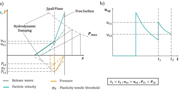
FIG. 7. Illustrations of shock wave propagation and reflection inducing pressure and particle velocity changes. In schema (a) are plotted particle velocity and pressure versus position. In schema (b) is plotted the particle velocity at spall plane during time.
B. Atomic segregation process
Atomic segregation pointed out by EDS measurements may be the result of a segregation that takes place during shear banding events. Thermodynamically, shock wave is considered as an adiabatic transformation that induces a jump of pressure and a decrease in volume resulting in a gain of free energy and temperature. Then localized plasticity responsible for cups and cones formation from initiation sites (metallurgical defect, free volume or STZ) also contribute to temperature and free energy elevation. This temperature rise (or free energy) is responsible for the drop of viscosity (glass transition or melting) allowing atomic mobility within a softened local neighborhood. Once the matter is locally in a liquid-like state along with the particle motion provided by shock wave, atoms could migrate. Since our material is made of various compounds possessing different masses (Zr: 91u, Cu: 63u, Al: 27u) inertial effects could emerge.
For an identical particle velocity, Zr atoms possess more kinetics energy than Cu and Al. Hence, segregation would take place during a phase of velocity decrease, where Cu and Al atoms would decelerate more rapidly than Zr atoms. To understand how such a scenario could happen, one may refer to Fig. 7 illustrating the variation of pressure and particle velocity during reflection and overlapping.
In early stages, matter is being compressed by the shock wave propagation that induces pressure, temperature and velocity jump. Once shock wave reaches the free-surface, reflec-tion occurs and the particle velocity rises (more or less doubled) while pressure drops to zero and temperature decreases (but stay higher than initial one). By overlapping at spal-lation plane, incident and reflected releases modify substantially particle velocity. Hence, the particle velocity increases at a velocity ut1 and tensile stresses result from overlapping.
Assuming a stress level above a tensile threshold σT (relative to plasticity activation, i.e.
shear band initiation), localization and viscosity drop take place soon after t1 and promote
migration. Taking account of hydrodynamic damping and release waves spreading, particle velocity decreases to ut2 at t2. As a result, the particle velocity ut2 at t2 is below ut1 at t1.
In short, after reaching σT the current viscosity drops (cf section IV A) and particle velocity
rises to ut1 resulting in a motion of atomic clusters. A little while after, particle velocity
decreases to ut2 and inertial effects forecast to happen due to atomic mass differences: Cu
and Al are slowed and Zr atoms continue on their path. This hypothesis is sufficient to understand why high Zr and Cu rate are respectively found on spall and sample fracture surfaces but not enough to explain aluminum constant rate on both surfaces.
According to Molecular Dynamic simulations of Cheng et al [41] on a Zr47Cu46Al7
show-ing Partial Differential Functions (PDF) for these compounds, Cu-Al and Zr-Al are the strongest bonds. Then Cu-Zr, Cu-Cu and finally Zr-Zr bonds are the weakest. Assum-ing that Cu-Al and Zr-Al are highly energetic compared to other bonds and that cracks propagate along paths minimizing energy, one may suggest that during separation crack would neglect as much as possible these bonds areas. Thus, only Cu-Cu, Zr-Zr and Cu-Zr bonds remain. Since Al atoms are the lighter but also strongly bonded to Cu and Zr, our results seem to suggest that crack split mostly Cu-Zr bonds during or after the segregation phenomenon.
As regards morphology, the composition segregation is possibly responsible for the cups and cones aspects. Zirconium possesses the highest melting temperature of the three: TZr
= 2130 K, TCu = 1350 K, TAl = 933 K. Furthermore, Yokoyama et al [42] showed that
Zr-rich ternary ZrCuAl (for a fixed value of Al) possess highest melting temperatures. Hence for a fixed temperature, areas highly concentrated in zirconium will show a higher viscosity than Cu-rich areas. This is clearly in agreement with our observation but also with the correlation of vein pattern size and viscosity level exposed by Deibler et al [34].
V. CONCLUSION
In summary, spalling process induced by laser has been studied on a Zr50Cu40Al10BMG.
Post-mortem analyses were conducted on recovered sample and spall. Scanning Electron Microscopy images revealed the presence of cups (on sample) and cones (on spall) features with various morphological aspects. Two distinct regions can be observed both on cups and cones: a smooth viscous-like in the center and a flat one with large vein-pattern in periphery. Energy Dispersive Spectroscopy measurements performed on fracture surface exhibited an atomic segregation that could take place during spallation. Cups appear rich in copper while cones are rich in zirconium. Outside of these features the initial composition rate is found. Atomic migration and segregation took place at spallation plane into the shear band initi-ation. On one hand, viscosity drop resulting from temperature increase and atomic disorder would favor atomic mobility. On the other hand, shock- and release waves propagation and interaction engender particle velocity variations. These two aspects promote atomic segregation through inertial effects.
The initiation and the propagation of cups and cones result from shear bands initiation and asymmetrical loading conditions at spalling plane induced by shock wave rarefaction. shear bands initiation originates from a quadrupolar-shaped atomic disorder firstly engen-dered by the compression front that would turn into shear bands when tensile front reaches spallation plane. During the separation process, crack arises from shear bands (softened paths) and creates cups and cones features.
VI. ACKNOWLEDGMENTS
The authors express their gratitude to all the LULI and SCANMAT staffs for technical support. The access to the LULI facility was provided through the Institute Laser Plasma (ILP, FR2707). This work was supported by DGA and ARED grants.
[1] W. Klement, R. Willens, and P. Duwez, Nature 187, 869 (1960). [2] A. Inoue, Acta Materialia 48, 279 (2000).
[4] C. A. Schuh, T. C. Hufnagel, and U. Ramamurty, Acta Materialia 55, 4067 (2007). [5] A. L. Greer, Y. Q. Cheng, and E. Ma, Mat. Sci. Eng. R 74, 71 (2013).
[6] B. Sun and W. Wang, Progr. Mech. Sci 74, 211 (2015).
[7] T. Hufnagel, C. Schuh, and M. Falk, Acta Materialia 109, 375 (2016).
[8] M. Martin, T. Sekine, T. Kobayashi, L. Kecskes, and N. Thadhani, Metal. Mater. Trans. A 38A, 2689 (2007).
[9] H. Togo, Y. Zhang, Y. Kawamura, and T. Mashimo, Mater. Sci. Eng. A 449–451, 264 (2007). [10] F. Xi, Y. Yu, C. Dai, Y. Zhang, and L. Cai, J. Appl. Phys. 108, 083537 (2010).
[11] S. Turneaure, J. Winey, and Y. Gupta, Appl. Phys. Letters 84, No 10, 1692 (2004). [12] S. Turneaure, J. Winey, and Y. Gupta, J. Appl. Phys. 100, 063522 (2006).
[13] B. Arman, S.-N. Luo, T. Germann, and T. C¸ a˘gin, Phys. Rev. B 81, 144201 (2010).
[14] I. Smirnov, S. Atroshenko, Y. Sudenkov, N. Morozov, W. Zheng, N. Naumova, and J. Shen, AIP Conf. Proc 1426, 1121 (2012).
[15] B. Luo, G. Wang, F. Tan, J. Zhao, C. Liu, and C. Sun, AIP Advances 5, 067161 (2015). [16] S. Zhuang, J. Lu, and G. Ravichandran, Appl. Phys. Letters 80, No 24, 4522 (2002). [17] C. Yang, R. Liu, Z. Zhan, L. Sun, and W. Wang, Mater. Sci. Eng. A 426, 298 (2006). [18] F. Yuan, V. Prakash, and J. Lewandowski, Mech. Materials 41, 886 (2009).
[19] J. Escobedo and Y. Gupta, J. Appl. Phys 107, 123502 (2010).
[20] B.-R. Sun, Z.-J. Zhan, B. Liang, R.-J. Zhang, and W.-K. Wang, Chin. Phys. Letters 28, No 9, 096102 (2011).
[21] L. Lu, W. Wang, M. Zhu, X. Gong, and S. Luo, Mater. Sci. Eng. A 651, 848 (2016). [22] A. Cao, Y. Cheng, and E. Ma, Acta Materialia 57, 5146 (2009).
[23] R. Maaß, D. Klaum¨unzer, and J. L¨offler, Acta Materialia 59, 3205 (2011).
[24] R. Maaß, D. Klaum¨unzer, G. Villard, P. Derlet, and J. L¨offler, Appl. Phys. Letters 100, 071904 (2012).
[25] P. Thurnheer, R. Maaß, K. laws, S. Pogatscher, and J. L¨offler, Acta Materialia 96, 428 (2015). [26] F. Cottet and M. Boustie, J. Appl. Phys. 66, 4067 (1989).
[27] M. Boustie and F. Cottet, J. Appl. Phys. 69, 7533 (1991).
[28] L. Lu, W. Wang, M. Zhu, X. Gong, and S. Luo, Mater. Sci. Eng. A 651, 848 (2016). [29] T. de Ress´eguier and F. Cottet, J. de Phys. IV 4, 629 (1994).
[31] E. Lescoute, T. D. Ress´eguier, J.-M. Chevalier, M. Boustie, J.-P. Cuq-Lelandais, and L. Berthe, Appl. Phys. Letters 95, 211905 (2009).
[32] Y. Yokoyama, A. Kobayashi, K. Fuhaura, and A. Inoue, Mat. Transactions 43:3, 571 (2002). [33] J. Colombier, P. Combis, F. Bonneau, R. L. Harzic, and E. Audouard, Phys. Rev. B 71,
165406 (2005).
[34] L. Deibler and J. Lewandowski, Mater. Sci. Eng. A 538, 259 (2012). [35] C. Pampillo, Scrip. Metall. 6, 915 (1972).
[36] H. Leamy, H. Chen, and T. Wang, Mater. Trans. 3, 699 (1972). [37] A. Argon, Acta Metall. 27, 47 (1979).
[38] M. Falk and J. Langer, Phys. Rev. E 57, No 6, 7192 (1998). [39] P. Schall, D. Weitz, and F. Spaepen, Science 318, 1895 (2007).
[40] A. Tanguy, F. Leonforte, and J.-L. Barrat, Eur. Phys. J. E 20, 355 (2006). [41] Y. Cheng, E. ma, and H. Sheng, Phys. Rev. Lett. 102, 245501 (2009).
[42] Y. Yokoyama, T. Ishikawa, J. T. Okada, Y. Watanabe, S. Nanao, and A. Inoue, J. Non-Crys. Solids 355, 317 (2009).