
Adaptation of CAIRO Meeting
Environment Toward Military
Collaboration Efforts
ByLuke Tan-Hsin Fu
Submitted to the Department of Electrical Engineering and Computer Science in Partial Fulfillment of the Requirements for the Degrees of
Bachelor of Science in Electrical Engineering and Computer Science and Master of Engineering in Electrical Engineering and Computer Science
at the Massachusetts Institute of Technology
MASSAi
May 24, 1999
Copyright @ 1999 Luke Tan-Hsin Fu. All Rights Reserved.
The author hereby grants to M.I.T. permission to reproduce and distribute publicly paper and electronic copies of this thesis
and to grant others the right to do so.
Author
C-)
NIApproved bN
Certified by
Accepted by
Department of Electrical Engineering and Computer Science May 24, 1999
7- /9 7
John J. Turkovich Charles Stark Draper Laboratory 1 Supervisor
Pemosky Pena-Mora _-Assistgnt Professor of Civil and Environmental Engineering
spervisor
\4'rthur C. Smith Chairman, Department Committee on Graduate Theses
Adaptation of CAIRO Meeting
Environment Toward Military
Collaboration Efforts
ByLuke Tan-Hsin Fu
Submitted to the
Department of Electrical Engineering and Computer Science
May 24, 1999
In Partial Fulfillment of the Requirements for the Degrees of Bachelor of Science in Electrical Engineering and Computer Science and Master of Engineering in Electrical Engineering and Computer Science
Abstract
During the course of tactical operations for military missions, many types of collaboration among individuals take place to assess situations, plan missions, and monitor the execution of operations. The process of coordination not only requires concurrent control in the placement and movement of units in a shared space but also concurrent control in multiple shared views that represent the situation. A prototype system was developed by taking two tactical planning applications and incorporating them into the collaboration model employed by CAIRO (Collaborative Agent Interaction control and synchROnization). The main focus of this research lies in the formalization of an architecture that supports military collaboration scenarios. This architecture lays the groundwork for development of a robust collaboration system that incorporates distributed databases.
Thesis Supervisor: Feniosky Pena-Mora
Title: Assistant Professor of Civil and Environmental Engineering
Technical Supervisor: John J. Turkovich
ACKNOWLEDGMENT May 24, 1999
This thesis was prepared at The Charles Stark Draper Laboratory, Inc., under IR&D Project 18570.
Publication of this thesis does not constitute approval by Draper or the sponsoring agency of the findings or conclusions contained herein. It is published for the exchange and stimulation of ideas.
Permission is hereby granted by the Author to the Massachusetts Institute of Technology to reproduce any or all of this thesis.
(author's signature)
First and foremost, I would like to thank Feniosky Pena-Mora for the assistance and encouragement he has provided me over the past year. I truly appreciate the confidence he had in me, a total stranger to him, in supporting me for this research position. In my one year under his tutelage, I have learned a great amount in the field of collaboration technology.
I am also extremely grateful to all of the individuals at Draper Laboratory who have assisted me during my learning process and made my stay here an enjoyable one: Milt Adams, Peter Scheidler, Mike Hutchins, Charlie Strauss, Tom Wells, and Harold Andrews. Of course, I am especially thankful to my supervisor, John Turkovich, for all of his insights, suggestions, and general compassion. Also, thank you, John, for taking such careful consideration in reviewing my thesis. I have never seen someone read a document so meticulously, and I applaud that.
Finally, I would like to express my gratitude to my family, who have supported me and provided me with guidance throughout my life. I would also like to thank my sister here at MIT, May Tse, for all the Almond Jello she made me during my thesis breaks. Last but not least, I am extremely grateful to all of my friends that have taken part in my trials and tribulations throughout my college years. Special thanks to my friends Robert Lin and Anne Park for getting me through this last term in my times of need. And even more thanks to my roommate Norman Tsao for staying up with me on the last night and to my masseuse Stefani Okasaki for saving my bad back.
Luke T. Fu May 1999
Contents
1.0 Introduction ... 10
1.1 Importance of This Research... 10
1.2 Objectives of This Research... 11
1.3 H ypothesis of This Research... 13
1.4 Benefits of This Research ... 14
2.0 Background... 15
2.1 The CA IRO System ... 15
2.1.1 The Architecture... 16 2.1.1.1 Collaboration M anager ... 16 2.1.1.1.1 M edia Drivers ... 17 2.1.1.1.2 M essage Server ... 18 2.1.1.2 Forum Server ... 18 2.1.1.2.1 Chairm an M eeting ... 19 2.1.1.2.2 Freestyle M eeting... 19 2.1.1.2.3 Lecture M eeting... 20 2.1.1.3 N am e Server ... 20 2.1.2 The Features... 20 2.1.2.1 The Interface... 21
2.1.2.2 The Status Panel ... 23
2.1.2.3 The M enus... 23
2.1.2.4 Side-Talk ... 25
2.1.2.5 The A genda Tool... 27
2.1.2.6 The A gent ... 27
2.2 M ilitary Applications ... 29
2.2.1 Geospatial View ... 29
2.2.2 Tem poral View ... 30
2.3 Sum m ary... 32
3.0 M ethodology... 33
3.1 Literature Review ... 33
3.1.1 M eeting Protocols ... 34
3.1.2 Cross-Platform Com patibility... 35
3.1.3 D atabase Integration... 35
3.2 Im plem entation ... 36
3.2.1 Fam iliarization with the CA IRO system ... 36
3.2.2 D evelopm ent of a Prototype ... 36
3.3 Results ... 37
3.3.1 D efinition of Requirem ents ... 37
3.4 Sum m ary... 38
4.0 Literature Review ... 39
4.1 M eeting Protocols ... 39
4.1.1 University of Illinois at Chicago Research ... 39
4.1.2 DiCE ... 41
4.1.2.1 Establishing a Conference ... 41
4.1.2.2 Controlling the Progress of a Conference ... 43
4.1.2.3 The Architecture... 43
4.1.2.3.1 Collaboration M anagem ent... 44
4.1.2.3.2 M edia Transmission Control... 45
4.1.2.3.3 User Interface... 45
4.1.3 Angelo System ... 46
4.1.4 M ITRE Research... 47
4.2 Cross-Platform Compatibility ... 49
4.2.1 Java Collaborative Environm ent... 49
4.2.2 SHASTRA... 51
4.2.3 Problem s with Personal Digital Assistants ... 52
4.2.3.1 Resource Lim itations ... 52
4.2.3.1.1 Display Lim itations... 53
4.2.3.1.2 Memory and Computational Power Limitations 55 4.2.3.2 Network Connectivity... 55
4.3 Database Integration ... 56
4.3.1 SHASTRA... 56
4.3.2 Synchronous Collaboration Environm ent... 57
4.3.3 M -RAM System ... 58
4.4 Sum m ary... ... 59
5.0 Im plem entation... 61
5.1 Initial CAIRO M odifications ... 61
5.1.1 Expressions ... 62
5.1.2 M ain Room ... 63
5.1.3 Casual Contact ... 64
5.2 Development of the Prototype... 65
5.2.1 Tem poral View Integration ... 66
5.2.2 Geospatial View Integration... 66
5.3 Sum m ary... ... 67
6.0 Results ...- -..-.. ---... 69
6.1 Database Notification vs. Event-Passing ... 69
6.1.1 Definitions... 70
6.1.2 Comparison of Issues ... 71
6.2 Requirem ents ... ... .. 71
6.2.1 M eeting Protocol... 71
6.2.1.1 M eeting Styles ... 71
6.2.1.2 Com m and Hierarchy... 72
6.2.2 Cross-Platform Com patibility... 74
6.3 Proposed Architecture... 76 6.3.1 The Architecture... 76 6.3.1.1 Participant... 77 6.3.1.2 Application... 77 6.3.1.4 Session Server... 78 6.3.1.4 Nam e Server... 78
6.3.1.5 Dom ain Databases ... 79
6.3.2 Possible Resource Allocations... 79
6.3.2.1 Sessions Using Independent Resources ... 81
6.3.2.2 Sessions Using Shared Resources... 84
6.3.2.3 Hierarchical Sessions... 86
6.3.2.4 Contingency M eetings ... 88
6.4 m ... 91
7.0 Conclusion... 92
List of Figures
Figure 2-1. Current CAIRO Architecture [Hussein 1995] ... 16
Figure 2-2. CAIRO Collaboration Manager Interface... 17
Figure 2-3. Forum Server Interface... 19
Figure 2-4. Name Server Interface... 20
Figure 2-5. Hallway of Meetings ... 21
Figure 2-6. Status Panel... 22
Figure 2-7. M enus... 24
Figure 2-8. Side-T alk ... 26
Figure 2-9. The A genda Tool... 27
Figure 2-10. The CAIRO Agent ... 28
Figure 2-11. Geospatial View Interface ... 30
Figure 2-12. Temporal View Interface... 31
Figure 3-1. Three Dimensions of Design Consideration ... 34
Figure 4-1. DiCE Architecture [Vin, et. al. 1993]... 44
Figure 4-2. Example Air Campaign Planning Scenario [Maybury 1997]... 48
Figure 4-3. JCE System Architecture [Abdel-Wahab, et. al. 1997]... 50
Figure 4-4. SHASTRA Application Architecture [Anupam & Bajaj 1993]... 52
Figure 4-5. Replacing Table with Formatted Text [Lauff & Gellersen 1997]... 54
Figure 4-6. Brokered Connection and Communication [Bajaj, et. al. 1995] ... 56
Figure 4-7. SCE System Architecture [Park, et. al. 1996]... 57
Figure 5-1. Snapshot of Expressions Tool ... 62
Figure 5-2. The M ain Room ... 64
Figure 5-3. Casual C ontact ... 65
Figure 6-1. Basic Structure of Command Hierarchy ... 73
Figure 6-2. Proposed Architecture ... 77
Figure 6-3. Initial State of Sessions Using Independent Resources... 82
Figure 6-4. Information Flow for Sessions Using Independent Resources... 84
Figure 6-5. Initial State of Sessions Using Shared Resources ... 85
Figure 6-6. Information Flow for Sessions Using Shared Resources ... 86
Figure 6-7. Architectural Representation of a Collaboration Hierarchy ... 87
Figure 6-8. Architectural Representation of Versioning ... 89
List of Tables
Table 5-1. List of Acknowledged Emoticons... 63 Table 6-1.Comparison of Event-Passing and Database Notification Models on Selected
Issu es... 7 0 Table 6-2. D atabase Dim ensions ... 80 Table 6-3. Affected Databases for Sessions Using Independent Resources ... 81 Table 6-4. Affected Databases for Sessions Using Shared Resources... 85
Chapter 1
1.0 Introduction
As technology moves rapidly into the world of networks and distributed environments, the government is looking forward to the wealth of opportunities that are being uncovered with this new form of communication. By combining the computing power of today's processors with real-time data transmission, virtual collaboration forums over distributed networks will become a powerful method of planning and design. Although there are presently legitimate concerns with bandwidth limitations and security issues with this emerging technology, by the time the virtual environment is implemented, these problems will most likely have been resolved [Ethos 1999, ZDNet
1999].
1.1 Importance of This Research
Situation assessment, planning, and execution monitoring of military missions are necessary to insure success. None of these functions can be conducted by a single individual. Command staffs must work together as highly disciplined, collaborating teams to coordinate missions successfully. Teams collaborate most effectively when they meet together in the same room [Lipnack & Stamps 1997]. This way, they can actively share information concerning their ideas, experiences, and opinions in various forms of media. Furthermore, individuals evoke qualitative attitudes such as agreement,
uncertainty, questioning, and so forth about the information they see through the use of gesturing and the use of audible, visual, and physical cues.
Networked computers provide a new opportunity for conducting these meetings. The numbers, kinds, and sizes of computer networks are increasing. These networks are being established to send electronic mail, transfer files, and even conduct video teleconferencing sessions. These three activities are already helping to increase communication among individuals. However, much more can be done to enhance the collaboration experience. Some forms of information that team members may exchange during collaboration sessions include text, maps, imagery, and charts. The ability to communicate using all of these forms of data can provide further insight to missions. Computers provide a mechanism through which these types of data can be distributed in an electronic format.
1.2 Objectives of This Research
The Collaborative Agent Interaction control and synchROnization (CAIRO) system is a distributed meeting environment that was developed at the Massachusetts Institute of Technology specifically for civil engineering project development [Benjamin 1998]. This system was created as part of the Da Vinci initiative whose goal is to "explore computer support mechanisms for enhancing distributed engineering design change negotiation" [Pena-Mora, et. al. 1996]. One of the primary goals of the CAIRO endeavor is to add structure to the collaboration process in the virtual space by defining various protocols of interaction that are commonplace in the physical space. The term "physical space" refers to the tangible world where individuals meet with one another face-to-face. On the other hand, "virtual space" represents the artificial environment that can be created and reached through computers. The functions of the virtual environment typically imitate the functions of the real world. In this respect, meeting protocols common to the physical world that control meetings are replaced by computer code that
Imagine a scenario in which different collaboration control strategies are employed during different phases of mission planning. In the initial phases, participants may want to adopt a "brainstorming" control structure, which allows them to interact simultaneously without restrictions. However, as a plan solidifies, a chairman control strategy, where individuals may only express their opinion after acknowledgement by the chairman, may be better suited to dealing with changing details. Finally, once a mission plan has been determined, staffs can brief the plan to their commanders about the plan using a lecture style meeting protocol. If these types of meeting rules can be replicated on the computer, computer collaboration efforts can be more effective.
The CAIRO initiative has taken the meeting protocols mentioned above and implemented them in its distributed meeting environment. Its collaboration scheme is based on an event-passing paradigm [Hussein 1997] to coordinate interactions among participants. This original CAIRO system contains no mechanism to utilize data from databases. The new collaboration system is designed incorporate both the passive nature of databases as a means of storing persistent information and also their active nature to notify subscribing users of information changes. This research looks at how to apply the database notification scheme into the CAIRO collaboration architecture. This new notification model, using an underlying distributed database structure, replaces the original CAIRO event-passing model. Many of the features presently using flat files will also be stored in the database to take full advantage of the new database design. Moreover, CAIRO will assume the role of a meeting facilitator using an information policy that defines and controls the flow of information among databases. This information policy not only defines the protocols for the meeting but also the availability of information to participants.
A working prototype is intended to demonstrate the collaboration enabling capabilities of the CAIRO meeting environment within the context of two different tactical planning applications: the Geospatial view and the Temporal view. This prototype will employ the event-passing model, which is central to the original CAIRO system. A sample scenario will be created to simulate the types of situations that may
occur during a mission planning meeting. These sample scenarios are intended to provide insight to the various kinds of interaction that need to be managed during collaborations. From this example, an architecture that incorporates the intended underlying database design is developed.
Ultimately, repeated iterations on this initial prototype and the architecture will be performed to refine the system into the desired product. New control structures and information policies will evolve as necessary to meet the military's demands. Furthermore, the architecture is expected to enable additional application views as they
evolve to be assimilated with relative ease.
From the work described above, a robust collaboration system is shaped, allowing for tactical mission planning to occur both among distributed units and within independent isolated units. In other words, participants may choose to work as part of a collaborative group or alone in their own private space. The completed system enables full hierarchical group structuring, agenda building, meeting control structures, and a detailed information policy to facilitate this interaction process.
1.3 Hypothesis of This Research
By developing and using a prototype of a military collaboration system, experience can be obtained for generating a roadmap for next generation systems. Based on the advantages and disadvantages of the prototype, a new set of requirements can be developed that define needed changes. This study produces a blueprint that documents the design path for a next generation system. Future developers can then follow this blueprint in creating the next version of the system.
The architecture for the new collaboration system will retain the important features of the current CAIRO system. In particular, CAIRO possesses many features that relate interaction norms in a meeting to a virtual environment. However, the ability to access databases needs to be incorporated to allow for storage and notification.
1.4 Benefits of This Research
The successful development of this collaboration system will greatly enhance the effectiveness of military missions where members of command staffs and expert advisors cannot all physically meet at the same location. First of all, this new system will enable completely distributed meetings to occur. Military staff can thus undertake situation assessment, planning, and execution monitoring without transporting all the staff members to one central location. Staff members will be able to collaborate with other staff members from locations wherever their physical presence is most valuable. Thus, dealing with unexpected issues from remote locations will become easier. In addition, it will be feasible for associates to participate in multiple meeting sessions simultaneously. This way, staff members and experts can contribute their value to many more organizations than they have in the past. Time, monetary resources, and lack of involvement do not have to be compromised.
As aforementioned, electronic information can be more easily encrypted to prevent third parties from acquiring important mission objectives. Furthermore, the realm of data representation is greatly augmented through the use of computers. Computers have the capability of displaying information in a variety of modes and contexts. All of these benefits lead to more comprehensive collaboration experiences for command staffs.
Chapter 2
2.0 Background
As stated in Chapter 1, the focus of this research is to develop a working prototype of a collaborative military planning system. This system integrates stand-alone military applications that have been developed at the Draper Laboratory with an existing collaboration system, CAIRO, developed at the Massachusetts Institute of Technology. However, to even begin considering an integration of two separate systems, one must first understand the underlying concepts behind each of the tools. A deep understanding of the issues that had to be considered in building the final product is also required. In this chapter, overviews of the CAIRO collaboration system built at MIT and the military applications built at Draper are provided.
2.1 The CAIRO System
The CAIRO system was developed in the Civil and Environmental Engineering department at the Massachusetts Institute of Technology as a tool to help engineers collaborate remotely to plan large engineering projects [Benjamin 1998, Hussein 1997]. It has functionality similar to a regular chat daemon; however, it has extra functionality that sets it apart from the typical chat rooms one may find on the Internet.
2.1.1 The Architecture
The distributed architecture of the CAIRO system is built upon the concept of client/server technology. Figure 2-1 illustrates an instance of the CAIRO system architecture. In this representation, there are four participants (a, b, c, and d) in the discourse. The design consists of three main elements: the Collaboration Manager, the Forum Server, and the Name Server. The following sections explain the roles of these constituents.
AGENT AGENT
'a 1' Participant (a) Participant (b) 'n a
£ --- ~ ~ ~- , Legend
X Media Driver
MSG MS ID Video Media Driver
Audio Media Driver Media Synchronization MSG and Transmission
A NAME SERVER BF-_
AGET rCollaboration Manager
AGENT
0----L
LS
Forum and Name ServersMSGMS-S-* Media Transmission Forum Control - -- --- Directory Service -- --- --- Drcoyeve Participant (c) Participant (d)
Figure 2-1. Current CAIRO Architecture [Hussein 1995]
2.1.1.1 Collaboration Manager
The collaboration manager is comprised of a number of media drivers and a message server. It also possesses a Graphical User Interface (GUI) that allows the user to easily navigate the system (see Figure 2-2). Encapsulated within the interface are numerous other tools, menus, and visual analogies that facilitate collaboration among participants. The interface and its features are discussed in Section 2.1.2.
iACT 1ID Desripti on E arly 5 trt Elarly Finish "Duoration
BASBJ I oncrete Foundatinr Walls NOV 15 19965 NOV 29 1 995,
CIA7 10 Em,- tructural Frame DiEC 9 1995 JAN 14 11391 2 BA7 Erect ~rairwpII and Elevato FEB 20 1997 APR P 1997 3 BAS1 0 ,t Mecharo' ci and Bin.ctr1 FEB 15 199T7 HAE R 9 197 N :.
N1arch
Figure 2-2. CAIRO Collaboration Manager Interface
2.1.1.1.1 Media Drivers
The term "media driver" describes a set of applications that users employ to transfer various forms of data to other users. The original version of CAIRO consists of a set of drivers that are specifically geared towards engineering project development. These drivers, which can also be seen in Figure 2-2, include a text driver, a whiteboard, a scheduler, and a design rationale and implementation tool (not pictured). The text driver permits the exchange of text messages among the clients so that they can communicate through the use of written language. The whiteboard provides a shared workspace that simulates an actual physical whiteboard that may be found in an office setting. This driver allows members to communicate information in the form of sketches or drawings. It is also capable of loading images and transmitting them to other participants. The
1:21:19 S.
scheduling tool includes an interface that describes a plan in the context of time. It lets users create and modify a schedule in a group setting. Lastly, the design rationale and implementation tool enables participants to collaborate about design issues of an engineering project. The availability of these tools greatly augments the ability to convey
specific engineering ideas from one person to another.
2.1.1.1.2 Message Server
This server handles all transmission of information between users and keeps track of membership in forums. The term "forum" is defined in Section 2.1.1.2. Messages that are exchanged between various participants in a forum are all in the form of TCP/IP datagrams. Each participant has his/her own handler that interprets those incoming messages and routes them to the appropriate drivers.
2.1.1.2 Forum Server
A forum is defined as "a structured group of participants involved in a collaborative effort" [Hussein 1995]. In this document, the terms "forum", "meeting",
"engagement", "conference", "session", and "collaboration instance" are used interchangeably, and all refer to this same definition. The forum server forms an analogy to the actual, physical meeting space. It keeps track of all of the individuals involved in a specific meeting and their current state (see Figure 2-3). A member of a forum may be in one of three states: active (logged in and listening), speaking (has control of the floor), or non-active (not logged in). In addition, the Forum Server maintains a log of events that occur within the forum for playback purposes. Thus, a user can go to specific entries on the agenda and replay the events that took place during that agenda item. The playback of the recorded log is only seen by the individual who requested the replay and is not saved in the event log.
Conferene Type Chairman
Members Actvty
[email protected] (LISTEN) [email protected] (LISTEN)
Figure 2-3. Forum Server Interface
The forum server also has the responsibility of regulating floor control, one of the most important features in CAIRO. Three different meeting styles are presently defined: chairman, freestyle, and lecture. Each of these styles exercises a set of controls to regulate when and to whom users can speak.
2.1.1.2.1 Chairman Meeting
The chairman meeting style within CAIRO is modeled after the real world chairman meeting. In this meeting strategy, one participant is designated by some prior decision to be the chairman of the engagement. This person is then given authority to determine who gets control of the floor. The chairman himself can take control of the floor as he/she wishes. However, other members of the meeting must request permission from the chair to speak. The chair then decides whether he/she will grant permission to the requestor. These actions are performed using the menus described in Section 2.1.2.3.
2.1.1.2.2 Freestyle Meeting
The freestyle meeting style has an informal composition. Unlike the chairman style, no one is in charge of the meeting. Instead, members are allowed to take the floor and speak of their own accord. This style of meeting is common for brainstorming sessions in order to keep the conference proceeding smoothly. People can speak freely as ideas flow into their minds, and thus, can contribute ideas without the constraint of obtaining permission from another individual.
2.1.1.2.3 Lecture Meeting
The lecture meeting style is, as can be inferred by its name, analogous to a lecture or classroom setting. In this case, the lecturer assumes a role similar to the chairman in the chairman strategy. However, primary communication is directed to the lecturer and no communication takes place between participants in the lecture.
2.1.1.3 Name Server
The Name Server centrally manages a global directory for the CAIRO system. This server catalogs a variety of information that can be retrieved by any user. This information includes the name, location, and status of each participant. Likewise, it retains knowledge about the forum's name, location, and status. When a user logs into the CAIRO system, the Name Server can provide information to the user such as the other individuals who are logged into the system and what forums are available to the user. Unbeknownst to the user, information about the Internet address of the other participants and the forums are sent to the client as well. Figure 2-4 exhibits the name server interface where the list of forums and users online are displayed.
Foruns People
PJoint roblem (OFF) [email protected] (ON) [email protected] (ON)
Figure 2-4. Name Server Interface
2.1.2 The Features
CAIRO possesses many resourceful features that produce an enriching collaboration experience. These features are what distinguish the CAIRO meeting environment from other collaboration systems, such as video teleconferencing, on the market today. The next few sections describe the features in more detail.
2.1.2.1 The Interface
One of the intended advantages of the CAIRO meeting environment compared to other collaboration systems available in the marketplace is that CAIRO provides a number of visual analogies to actual physical meeting spaces. As an example, the image of the table visible in Figure 2-2 can take on two different shapes. The round version cues the viewer that the meeting he/she is participating in is a freestyle meeting. In contrast, a rectangular shaped table denotes a meeting with a chairman. These visual analogies have dual concepts in the physical world that may be familiar to the typical individuals. As another example, the status panel located in the upper half of the main collaboration window in Figure 2-2 contributes information about whether a participant is speaking, being addressed, or being requested. This feature is described more fully in Section 2.1.2.2.
Figure 2-5. Hallway of Meetings
Figure 2-5 demonstrates a third instance of the intended richness of the visual medium. In this window, the analogy of a hallway is used to represent the choice of meetings that are available at a particular instance in time. Each door represents a separate meeting and has a title describing the meeting over it. At the left and right sides of the image lie extensions to the hallway through which users can to reach more rooms. Once a user finds the room that he/she would like to join, he/she simply clicks on the corresponding door. It then opens as shown in Figure 2-5. An open door signifies that a room has been entered. Therefore, this doorway represents an entry to our virtual meeting.
Red
Yellow
K
Figure 2-6. Status Panel
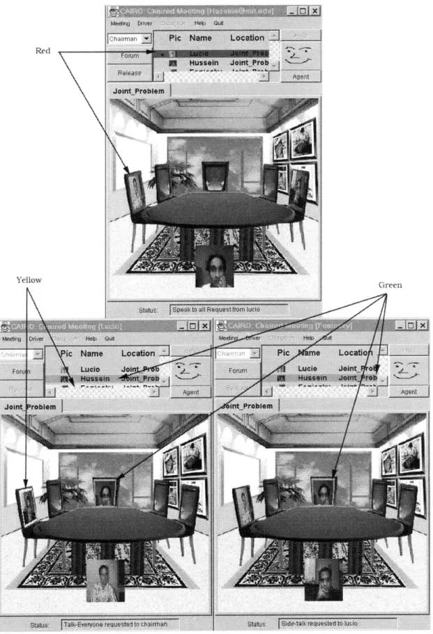
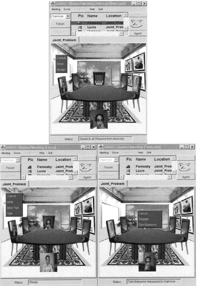
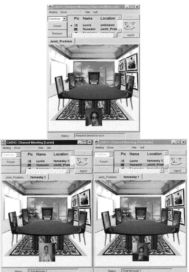
For each of the next three figures (Figures 2-6 through 2-8), the users are identified by name as Lucio, Feniosky, and Hussein. These names are used to refer to these users in the rest of this chapter. Hussein's interface resides in the top window while Lucio and Feniosky are in the bottom left and right windows respectively. Their names also appear in the title bar of each window. The rectangular table in this snapshot intends to convey that a chairman style meeting is in progress. Both Feniosky and Lucio's windows show Hussein as the chairman. Hussein's photo also appears at the far end of the table to signify his status within the meeting. Hussein, in contrast, sees no one at the other end of the table.
2.1.2.2 The Status Panel
Figure 2-6 exhibits one example of the abundance of information that can be conveyed to the user through the status panel. At first glance, one may think that the status panel only shows the name and location of a user. However, much more information is concealed in this panel. In this screenshot, the Feniosky client, at the bottom left, has gained permission to speak to the entire group. The state of the meeting can be determined by a quick glance at the status panel. The green highlight on Hussein's name and picture in the windows of Feniosky and Lucio signal that Hussein presently has control of the floor. Similarly, on the Hussein's screen, the dots next to the names of Feniosky (cannot be seen due to size of status panel) and Lucio tell him that he is speaking to the other two participants. The red highlights seen in Hussein's interface around both Lucio's name and image signal to Hussein that Lucio has requested permission to speak. In this scenario, Hussein is the chairman, so he receives all requests to speak. Finally, the yellow highlights that appear around Feniosky's name and image in Lucio's window signal to Lucio that Feniosky is requesting a side-talk with him.
2.1.2.3 The Menus
CAIRO provides a series of pop-up menus for users to moderate the collaboration process. For example, if a user wishes to get permission to speak to the whole group,
he/she can click on the table, which in turn generates a menu with three options as illustrated in Figure 2-7. In this example, Feniosky has activated the table menu on his window. The table menu gives Feniosky the opportunity to send a request to the chairman of the meeting, Hussein, by clicking on the "Talk-Everyone" option.
Lucio, on the lower left, has exercised the side-talk menu by clicking on another participant's image. The "Talk" and "Side-Talk" options both send requests to speak to the selected user. However, the "Talk" option, if accepted, only establishes a direct link between the two users within the context of the meeting. On the other hand, the "Side-Talk" menu item causes a new collaboration instance to be initiated. The Side-Talk feature is explained in more detail in Section 2.1.2.4. The "Invite" feature is only enabled when a side-talk instance is active. It allows participants within a Side-Talk to bring other collaborators into the Side-Talk. Finally, a user can respond to a request from another participant by clicking on that participant's image as Hussein is doing at the top. This click of the mouse generates yet another menu that allows him to either accept or deny the request. These menus attempt to simplify communication by reducing the protocol between participants to mouse clicks.
2.1.2.4 Side-Talk
In Figure 2-8, a Side-Talk is in progress between Feniosky and Lucio. In the main image panel, notice that their interfaces contain an extra tab labeled "feniosky 1". This tab, consisting of the side-talk initiator's name and an ordinal number, represents a Side-Talk. The number is incremented for each side-talk that is initiated, thus allowing for one person to initiate and participate in multiple Side-Talk instances simultaneously. In this case, information disseminated in this folder tab is only transferred between Feniosky and Lucio. Hussein sees none of their conversation and is completely unaware that this side conversation is taking place. This feature allows a subgroup of a conference to speak privately during a meeting. One can conceive a scenario in which a subcommittee is formed to discuss a side issue. In this case, the side-talk function could be used for the purpose of the subcommittee. Lastly, participants of the Side-Talk can switch between
CAIR cI Chaid MiS
tabs, and by doing so, can alternate their participation between the main meeting and the sidebar conversation.
2.1.2.5 The Agenda Tool
The agenda tool identifies the order of a meeting. As in a physical meeting, the agenda contains an outline of topics to be discussed. The agenda in CAIRO works in conjunction with the forum to control the flow of a meeting. The agenda recognizes the duration of each agenda item. CAIRO also provides an agenda wizard tool that can be run to interactively create an agenda for a meeting. This wizard has a graphical user interface that guides users through the steps in generating a schedule for a meeting. The agenda tool, presented in Figure 2-9, is simply comprised of a window that has a timer to keep track of the time spent on an agenda item and a view of the items in the agenda. The panels, from left to right, identify the name of the agenda item, the person in charge, and the style of meeting.
Agenda Display [husseingmit.edu] B gM
Time: 00:01:13 a3
introductions KarimHussein Chairman ExpIoration of Joint Alternativ Lucio Soielman Free Style Select A Joint Alternative Feniosky Pena-Mora Chairman
Conclusion Karim Hussein Chairman
View Nx R Close
Figure 2-9. The Agenda Tool
2.1.2.6 The Agent
The CAIRO agent is one of the integral components that differentiates CAIRO from other collaboration systems. The agent is a program that monitors the actions of the users, residing with the moderator of the meeting. The agent procures information from the interactions among users and tries to make intelligent suggestions to the moderator that may increase efficiency in the meeting proceedings. Currently, the CAIRO agent
possesses only limited functionality, focusing on the agenda, certain textual cues, and request activity.
During a meeting, if the time allotted for an agenda item has expired, the agent will prompt the moderator to continue to the next agenda item. In this case, the agent is a passive timer for the user. The client can choose to accept the suggestion or reject it depending on how he/she feels the meeting is proceeding. However, the agent still serves as a reminder that keeps the participants on topic and in-line with their meeting agenda.
The agent also reacts to certain textual phrases that are sent and received through the text driver. It parses the text that is being delivered for specific key words. For example, if the agent sees a word such as "explain", it may suggest to the moderator that he/she change the meeting style to a lecture control strategy. If the word "discuss" were used, then the agent would suggest that the freestyle meeting strategy be employed. Again, the user can then decide whether to accept the suggestion or not.
Figure 2-10. The CAIRO Agent
Finally, the agent also responds to actions that are being taken by the users. If the agent notices that a lot of requests to speak are being made by the participants, then it may recommend that a freestyle meeting strategy be applied. This way, the meeting may run more smoothly if users do not have to constantly request permission to speak. Figure 2-10 shows a sample view of the CAIRO agent.
2.2 Military Applications
Two main applications that are being developed within the context of tactical mission planning are named the Geospatial View [Strauss 1999] and the Temporal View [Hutchins 1999]. These applications are being developed separately as simple standalone programs that allow situation assessment, planning, and execution monitoring to take place independently on a single workstation. These tools were added as new application drivers within CAIRO during the implementation phase.
2.2.1 Geospatial View
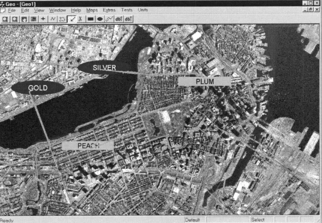
The Geospatial View presents the tactical node mission problems from a spatial perspective. Figure 2-11 illustrates this view with annotations on imagery. The tool possesses the following functionality:
0 Allow users to load in maps and imagery from a database and bring them into the view port. These images can consist of actual satellite imagery as shown in Figure 2-11. Of course, there exists the ability to zoom in and out of an image and to pan through various points on the map.
* Locations may be pinpointed and marked using designated code names. The shape of these location markers also provides information about the status of the area of interest.
* These locations can be linked by paths determined by the user that depict routes to be taken by units. The application also provides a route editor that permits detailed adjustments to routes through a zoomed in view.
o Times can also be specified for locations and checkpoints along each path. An animation tool can be used to observe how various units move with respect to time. In this way, a complete mission plan depicting the spatial arrangement of
units and their movements can be created. Snapshots of the spatial relationship of all points of interest can be generated for specific moments in time.
Figure 2-11. Geospatial View Interface
Although this overview does not cover the full functionality of the Geospatial View application or plans for additional features, it does cover its primary functionality in its current state. This summary intends to provide the reader with an impression of the range of utility that accompanies this application.
2.2.2 Temporal View
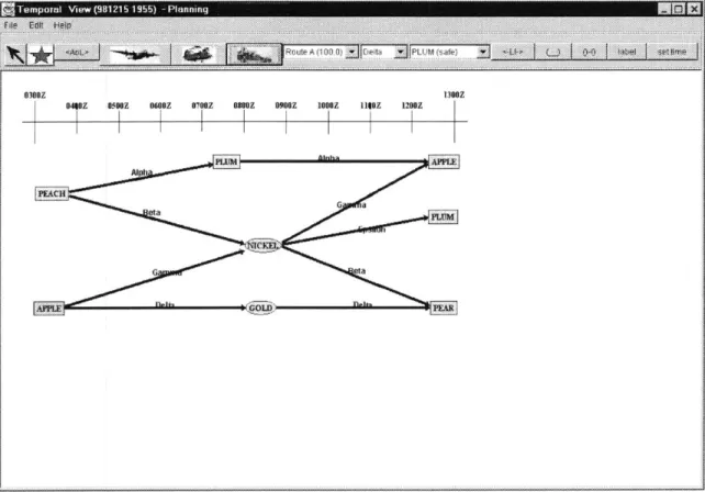
On the other hand, the Temporal View, displayed in Figure 2-12, approaches the planning issue from a fourth dimension, time. This view allows one to create a visual schedule that uses the locations and movements along routes described in the Geospatial View. The functionality attributed to the Temporal View application include:
* A timeline that runs along the top of the application view currently specifies an eleven-hour duration of time. As of now, this timeline remains static but in future revisions, it can be edited and customized for each particular mission.
... .. t
HouteSa A4 (100.0) Ilpt '.D L (
I
settas050Z 0600Z 67HZ hMZ 0900Z 1000Z 11602 1200Z
I I I I I I I
I I I I I I I
1300Z
Figure 2-12. Temporal View Interface
* Rectangles and ellipses indicate various locations.
* Directed lines between rectangles and/or ellipses specify movements from one location to another. Currently, the choice of transportation modes is static, but in the future, other forms of transportation should be loadable from the database.
* Annotations along directed lines identify units by code name as well. 0300Z
The Temporal View application provides a tactical node planning view from the perspective of the time dimension. It allows a glut of information to be passed to users in a visually descriptive schedule format.
2.3 Summary
This chapter presents a brief overview of the three systems that are to be integrated. The important features of each of the systems are explored and sample screenshots are offered to provide the reader with some familiarity with the interfaces. Knowledge of the systems and their capabilities was necessary for any attempt at integration.
Chapter 3
3.0 Methodology
For any substantial research effort, an approach outlining the steps leading to the eventual goal is vital to its success. In this chapter, the main considerations of this study are elucidated. The research process is comprised of a literature review, an integration of various systems, and the subsequent results along with their relationship to the final objective are described.
3.1 Literature Review
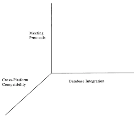
Three practical considerations dominate the design of a new collaboration system. These concepts are represented in Figure 3-1 as the axes of a three dimensional space. They are:
1. Meeting Protocols
2. Cross-Platform Compatibility
3. Database Integration
To gain a better understanding of how current technologies approach these concepts, a review of other systems developed within the context of these three dimensions was conducted. Each of the systems researched was compared to what
currently exists in the CAIRO initiative. If applicable, revelations of how each complementary system can contribute to the development of a new system were elucidated as well. Those research efforts with applicable architectures are disclosed in Chapter 4 and related to the study in collaborative environments that is being conducted here. The following subsections provide further explication of the three dimensions and how they pertain to the investigation in this research.
Meeting Protocols
Cross-Platform Database Integration Compatibility
Figure 3-1. Three Dimensions of Design Consideration
3.1.1 Meeting Protocols
Meeting protocols are affected and influenced by the hierarchical command and control structures in military organizations. The overhead for conducting meetings might be drastically reduced by having computers handle a lot of the administrative tasks during meetings. For planning meetings, much of the control should probably be delegated to the participants. They shall determine who should get what information and when. However, during the execution monitoring phase where time is of critical essence, rules might be
developed to manage the routes of communication flow. Methods might have to be developed to enable rapid dissemination of information through a chain of command.
3.1.2 Cross-Platform Compatibility
With every attempt to reduce the number of different kinds of computers and operating systems available in the market, there still exists extensive heterogeneity in hardware and software. As some organizations attempt to standardize on Windows NT, others continue to advocate Unix platforms. At the same time, handheld, palmtop, and wearable computers with their own unique operating systems are beginning to permeate society. Due to the nature of military collaboration, field agents may occasionally have to be able to conduct collaboration sessions with base sites. In this case, they may be using a small hand held device that has limited resources such as memory and display ability. To deal with these less equipped systems, a textual interface may be employed to replace the regular graphical interface. A robust solution would be one where a collaboration system is generic enough to run on all existing and future hardware platforms. Thus, these design considerations should be taken into account as well.
3.1.3 Database Integration
The method of distributing data between applications will be changed from the current event-passing model to one that uses an underlying database to facilitate the communication. One of the main incentives for this transition is the unreliability of the event-passing paradigm. During a collaboration instance, for example, if a message from one client to another is somehow lost, the two views will no longer be synchronized. Over time, this error may be propagated to produce contaminated results.
The system depends on the overall reliability of its network. With an event-passing paradigm, lost information cannot be retrieved at a central repository because it simply does not exist. To permit resynchronization after reconnection, a database is introduced. Each participant's view is synchronized with the information in the database. When an individual loses his/her connection to the database, the changes that were made
during the lapse in communication are reflected as soon as the client is reconnected to the system. In addition, the database is a site where data can be stored. The existence of an underlying database enables data to persist from one session to another. Multiple databases may retain duplicate copies of information such that if one database is destroyed, the information lost in one database can be recovered from another. However, protocol for database interaction and synchronization needs to be defined.
3.2 Implementation
The integration of the Draper applications into the framework of CAIRO consisted of two phases. The goal of the first phase was to gain familiarity with the CAIRO architecture by integrating minor features from another collaboration system into the CAIRO system. The second step was to take the knowledge gained from the previous phase and apply it to the actual integration of the military tools with the CAIRO meeting environment. Both of these procedures are detailed in Chapter 5 while a brief summary is presented in the next two sections.
3.2.1 Familiarization with the CAIRO system
Before development could be initiated on either of the Draper applications, knowledge of the architectures and underlying code must be gained. To do so, some initial modifications were performed on the CAIRO system. These modifications allowed for a better understanding of the program and its implementation so that integration of the military applications could be conducted with detailed comprehension of the underlying event-passing model. To achieve this level of understanding, several new drivers were added.
3.2.2 Development of a Prototype
After completing the modifications described in the previous section, a prototype system that allows distributed collaboration between clients for mission planning
purposes was implemented. The Temporal and Geospatial View applications were integrated within the context of the CAIRO system, taking advantage of the predefined event-passing paradigm provided by CAIRO. This prototype served as a first iteration upon the distributed collaborative system toward the target system. It provides a solid framework upon which new modifications and versions of the program may be built. Furthermore, this prototype can then be used to study the types of interactions that may occur and provide insight on how to deal with them.
3.3 Results
After the hands-on implementation phase, the research assumed a more introspective nature. Based on the conclusions from the literature review and the prototype, a set of requirements that are to be met by a new collaboration system was determined. Then, the architecture of a new database collaborative system was designed conforming to the aforementioned requirements. These results are explored in Chapter 6.
3.3.1 Definition of Requirements
Upon completion of the prototype, an evaluation of its functionality was conducted. This evaluation led to a set of requirements upon which an architecture was designed. In addition, a study of the advantages and disadvantages of the event-passing model compared to a database notification model is found in Section 6.1. This assessment elucidates the need to change toward a collaboration design using a database framework. In particular, the focus of the requirements revolves around the three dimensions outlined earlier in this chapter.
3.3.2 Formalization of an Architecture
Based upon the requirements outlined from the results of Section 3.5, a preliminary architecture for the new military collaboration system was designed. This architecture is built upon a distributed database structure. Several different collaboration
scenarios within a military context are discussed in relation to the new architecture. These scenarios provide a comprehensive review of how the system responds to certain circumstances and aims to confirm the robustness of the design.
3.4 Summary
The eventual architectural design, employing a database notification paradigm, was generated by following the process described in this chapter. The methodology practiced here is comprised of three main stages. First, a review of previous studies in the collaboration arena was conducted. Then, a rudimentary prototype was built using the collaboration framework of the CAIRO system with the Draper military applications. Finally, a database architecture was designed that supports distributed collaboration efforts for situation assessment, mission planning, and execution monitoring.
Chapter 4
4.0 Literature Review
In this section, several other complementary collaboration systems are examined which tackle one or more of the following issues: meeting protocols, platform compatibility, and database integration. Following each synopsis is a brief analysis of the system compared with CAIRO and the objectives of this research project.
4.1 Meeting Protocols
In the following subsections, research from the University of Illinois at Chicago, IBM T.J. Watson Research Center, MIT, and MITRE are presented. These systems describe protocol concepts that span meeting control structures, software agents, and command hierarchies.
4.1.1
University of Illinois at Chicago Research
Research at the University of Illinois at Chicago's Department of Electrical Engineering and Computer Science looks at the concept of collaboration using the World Wide Web [Chang, et. al. 1997]. The results of their study centered on four central ideas. The next few paragraphs expound upon their ideas and how they pertain to the research conducted in this document.
Their first finding is that a collaboration system should be Web-based. Although CAIRO does not operate specifically as a Web-based application in the conventional sense (as an applet within a web browser), the underlying communication technology in fact takes full advantage of Internet capabilities through the use of the TCP/IP network protocol to deliver and receive messages within the system. Security measures built into web browsers such as Netscape Navigator place restrictions upon message transmission, so the effort to create an applet in CAIRO had to be abandoned in lieu of an independent application.
Secondly, the Chicago research group contends that such a system must be supported in a multimedia environment. Currently, CAIRO allows for text and visual communication between individuals. Full audio and video streaming capabilities will eventually be added to CAIRO to augment the collaboration process. This functionality can create a more natural environment for communication to occur in a vastly electronic setting.
In this study, it was also determined that a virtual conferencing environment would have to possess a set of "floor control rules" similar to Robert's Rules of Order [Robert 1996]. Robert's Rules of Order are a set of guidelines that describe the general rules of parliamentary procedure. They describe a methodology of how members of a deliberative assembly can speak and vote. In CAIRO, there have already been these different rules of order defined with the capability of adding more as needed. These meeting styles, as discussed earlier, control who is allowed to speak when and to whom. In addition, the paper [Chang, et. al. 1997] points out that the rules should be modified to account for asynchronous collaboration efforts. This area has not been fully explored in the CAIRO initiative and could be a great source of improvement in the technology.
Lastly, the authors [Chang, et. al. 1997] state that a formal language for defining meetings needs to be studied. They present the concept of a Meeting Declaration Language (MDL). This original language allows users to describe the rules and operations that are to be followed in a meeting. Much like a programming language, a compiler is then used to process a user's input and create the protocols and structure for
the meeting. CAIRO approaches this problem from a user's perspective. Instead of developing a new language for defining meetings, CAIRO simply employs an easy to follow interface that steps the user through various setup options. This simple program then applies the user's choices to initiate a forum and an agenda for that meeting.
4.1.2 DiCE
At IBM T.J. Watson Research Center, a study is being conducted on methods of collaboration management [Vin, et. al. 1993]. Their research serves as a foundation for the Distributed Collaborative Environment (DiCE) being developed at their facility. Their research approach comes from a theoretical perspective. Here, the main results of their research with some description as to how CAIRO resolves each of the issues are presented. In addition, the architecture of the DiCE system is depicted with an analysis of its advantages and disadvantages.
4.1.2.1 Establishing a Conference
The essence of the paper lies in its explication of what they call "Conference Management" [Vin, et. al. 1993]. They believe that the process of establishing a conference warrants some attention. In fact, they believe it consists of three important phases:
1. Invitation and arbitration
2. Negotiation
3. Setup
Invitation and arbitration deals with the tasks that occur prior to meetings such as sending invitations for a meeting, electing one person to initiate a meeting, collecting responses of participation, and the establishment of connectivity. Presently, the CAIRO system has not effectively tackled many of these problems relating to pre-meeting
situations. A skeleton framework does exist for sending out e-mails that invite participants to a meeting. CAIRO also operates under the assumption that an arbitrator, who establishes the meeting, will be selected through prior communication using other means of notification. This feature does not exist in CAIRO. The arbitrator would then collect responses through e-mails as well. The CAIRO environment consists of an interface for creating and entering meetings, but establishment of connectivity between clients is done automatically by CAIRO's collaboration framework.
The negotiation phase refers to the stage when the operational parameters of the conference are defined. They bring forth two main problems to consider:
0 Management of heterogeneous hardware and network environments - For CAIRO, network heterogeneity is not a major concern since the networking aspects of the system are built around the TCP/IP convention. As long as a system adheres to the networking protocol of TCP/IP as most computers these days do, networking will not be a problem for users of the CAIRO system. The problem with hardware compatibility is definitely an issue, though. Presently, the only focus on hardware issues has been portability across different operating systems. More research will have to be done into the actual hardware capabilities of a system. This concept is further examined in Section 4.2.
0 Flexibility of participation in conferences - This phrase describes how a collaboration system should allow participants to decide upon their own mode of participation. Once again, CAIRO does not venture into this realm of operation. For users of the CAIRO system, the arbitrator who possesses the power to define the meeting and its requirements does most of the negotiation. However, some research in this area may be valuable.
The final stage, which the authors [Vin, et. al. 1993] present, is that of setup. The setup phase creates a system of long-term connectivity for the clients. CAIRO encapsulates much of the setup and connection of the numerous clients. Once a meeting
is entered in the CAIRO environment, the proper connections and links are created for the duration of the collaboration instance.
4.1.2.2 Controlling the Progress of a Conference
The authors touch upon the concept that conference interactions over a network may have to be coordinated in some manner. Their view is one of necessity rather than one of efficiency. They point out that applications such as shared whiteboards or concurrent editors may require some sort of access controls in case two or more users attempt to change the same data simultaneously. In their paper, they propose a simple baton-passing schema. This strategy centers upon a predefined number of batons, which represent access privileges to a particular application. A participant gains control of a baton by procuring it from the previous owner. Of course, this action requires that the owner permit the requesting participant to take control of the baton. CAIRO, on the other hand, focuses its attention on the concept of coordination within a conference. CAIRO has three defined control strategies that are expounded upon in Section 2.1.2, which are based upon the concept of tokens. Although the current version of CAIRO does not support the baton-passing method of collaboration, this strategy can easily be incorporated into the system using the token approach.
4.1.2.3 The Architecture
The software architecture for the DiCE system has been reproduced in Figure 4-1. The acronyms found in the figure are revealed in the following sections. After some preliminary analysis, one can see that the architecture parallels the CAIRO collaboration manager design in many ways. The system is composed of three main components: a collaboration management unit (CMU), media transmission control unit (MTU), and interfaces.
4.1.2.3.1 Collaboration Management
The collaboration management functionality can be further broken down into three more sections:
0 Multimedia server (MMS): The MMS provides a naming and addressing schema for agents so that invitations can be conducted by name. It is also responsible for creating a Collaboration Management Unit (CMU)
Communication Pipe
Figure 4-1. DiCE Architecture [Vin, et. al. 1993]
* Collaboration management unit (CMU): This module represents the user, performing the functions of a "schedule keeper". The CMU is in charge of generating a Conference Control Unit (CCU) for each conference that is started. The CMU and MMS together incorporate the functionality of the Name Server in the CAIRO architecture.
0 Conference control unit (CCU): The CCU exists as an analogy to an actual
conference and encapsulates the meeting structure and controls. It takes care of defining the meeting within the context of the conference and setting access privileges for the participants. Multiple instances of this module may be present since users may participate in multiple conferences simultaneously. This element mimics the role of the Forum Server within CAIRO.
4.1.2.3.2 Media Transmission Control
The Media Transmission Units (MTU) regulates the exchange of information between clients. Again, notice a similarity between this component and the Message Server in CAIRO. Although their implementations most likely differ, both elements serve the same function: directing the transmission of information from one client to another. Moreover, in the DiCE architecture, a MTU exists for each application driver whereas in CAIRO, only one Message Server exists for each client that is in charge of all communications for that client.
4.1.2.3.3 User Interface
The user interface is composed of four different interfaces at the moment. They include:
0 Collaboration Interface (CI): The Collaboration Interface acts as the go-between for the user and the underlying collaboration system. In reality, the Collaboration Interface is similar in functionality to the Collaboration Manager in CAIRO. It allows the user to place, join, and terminate conferences as well as adding and deleting applications within the conference.
e Video Interface (VI): The Video Interface is comprised of two parts: 1. Video Window, and 2. Video Control Panel. The role of the Video Window is simply to display the motion video at 30 frames/sec. It provides information about the participants in a meeting and provides a series of menu options to alter the source
![Figure 2-1. Current CAIRO Architecture [Hussein 1995]](https://thumb-eu.123doks.com/thumbv2/123doknet/13854640.445023/16.918.112.679.392.732/figure-current-cairo-architecture-hussein.webp)


![Figure 4-1. DiCE Architecture [Vin, et. al. 1993]](https://thumb-eu.123doks.com/thumbv2/123doknet/13854640.445023/44.918.209.656.429.792/figure-dice-architecture-vin-et.webp)
