The Addition of a Calender Machine to a Pyrolytic
Graphite Sheet Production Plant
by MASSACHL
Ernest
Knute Svenson
OF TB.S.E. Mechanical Engineering
Duke University, 2010
LIBI
Submitted to the Department of Mechanical Engineering in partial fulfillment of the requirements for the degree of
Master of Engineering in Manufacturing at the
MASSACHUSETTS INSTITUTE OF TECHNOLOGY
September 2014
2014 Ernest Knute Svenson
All rights reserved
The author hereby grants to MIT permission to reproduce and to
distribute publicly paper and electronic copies ofthe thesis document in whole or in part in any medium now known or hereafter created.
Signature redacted
Author:...Department of Mechanical Engineering August 15, 2014
Certified by:... ...--
Signature redacted
-.--,..
.. .VDr.
David E. HardtRalph E. & Eloise F. Cross Professor of Mechanical Engineering Thesis Advisor
Signature redacted
A ccepted by: ...
---'eebDr. David E. Hardt Ralph E. & Eloise F. Cross Professor of Mechanical Engineering, Chairman Department Committee on Graduate Students.
SETS INSTITUTE, ECHNOLOGY
The Addition of a Calender Machine to a Pyrolytic
Graphite Sheet Production Plant
by
Ernest Knute Svenson
Submitted to the Department of Mechanical Engineering In Partial Fulfillment of the Requirements for the Degree of
Master of Engineering in Manufacturing
Abstract
This thesis documents the process and challenges of adding a new calender machine to AvCarb Material Solutions' pyrolytic graphite production plant. Before the machine could be used for mass production, several experiments needed to be conducted to better understand the capabilities of the machine.
A process control procedure was designed to set up the machine to produce parts within
specification. By using a one-factor-at-a-time approach, the process capability (Cpk) ofthe calender machine can be significantly improved. Additionally, the calender machine was used to investigate the significance of common defects on the uncalendered material. Experiments show that spots that are 3 millimeters or less, scratches, and certain ripples do not cause a destructive effect on the calendered sheet; therefore, sheets with these defects can be safely passed through the quality inspection stage. Foreign object debris causes bubbles, which are destructive effects, to appear on the calendered sheet; therefore, sheets with foreign object debris should not pass inspection. However, if the foreign object debris is physically removed from the sheet before calendering, the resulting sheet will not have any destructive defects. Thus, by not rejecting uncalendered sheets with certain defects, AvCarb can improve its process yield.
Additionally, a thermal conductivity test apparatus was designed and used to determine that the calendered heat spreader is 70% more thermally conductive than its uncalendered counterpart.
Thesis Supervisor: David Hardt
Acknowledgements
I would like to take this opportunity to thank the many people for assisting me on this project and for making my year at MIT unforgettable one.
First, I would like to thank Dr. David Hardt for encouraging me to think critically and creatively and encouraging the management at AvCarb to challenge me with more critical issues. This project would not have been as interesting nor as successful without that push. I would also like to thank him and Jose Pacheco for giving me an opportunity to be a part of the MEngM program and for their guidance on all my projects over the year.
I wish to share my gratitude to Don Connors, Kathy Rutter, and the entire AvCarb team for an
amazing summer. I would especially like to thank Kathy for graciously donating much of her time sharing her expertise on the heat spreader production process and listening to wild ideas from a few MIT students. Those long conversations were the key to our progress over the summer.
I also wish to express my appreciation to my MIT colleagues at AvCarb, Chase Olle and Yugank
Chawla, for their help when I was in troubleshooting mode. It was a pleasure to bounce those wild ideas off each other.
Similarly, I would like to thank all of my classmates in the MEngM cohort for your friendship and keeping me sane during the year. All those late nights working on long reports gave me the mental fortitude to tackle this document.
Table of Contents
Chapter 1. Introduction... 11
1.1 Background and Com pany H istory... 11
1.2 Industry U se for Pyrolytic Graphite Sheets... 11
1.3 Research M otivation ... 13
1.4 Brief Background on Calendering Issues... 15
1.5 Problem Statem ent ... 16
1.6 Thesis Overview ... 17
Chapter 2. M aterials and the M anufacturing Process ... 18
2.1 Overview ... 18
2.2 Polyim ide Film ... 18
2.3 Graphite Foil Sheet... 19
2.4 Pyrolytic Graphite Sheet... 19
2.5 Overview of the M anufacturing Process... 20
2.5.1 Stacking... 20
2.5.2 Carbonization of Polyim ide Film ... 21
2.5.3 Graphitization of Polyim ide Film ... 22
2.5.4 U nstacking and Inspection... 23
2.5.5 Types of D efects ... 23
Chapter 3. Calendering ... 29
3.1 Overview ... 29
3.2 Calendering Basics... 29
3.3 M ethods of Controlling Thickness... 30
3.3.1 Force Control ... 30
3.3.2 D isplacem ent Control ... 31
3.3.3 Speed of the Rolls ... 34
3.3.4 Shape of the Rolls ... 34
3.4 Physics of the Com pression in the Calender... 36
Chapter 4. Integrating the Calender M achine ... 38
4.2 D escription of A vCarb's Calender M achine... 38
4.3 Initial Installation Steps... 38
4.3.1 D eviations in Thickness... 39
4.3.2 W rinkles... 42
4.3.3 Bubbles ... 44
4.4 Procedure for Reaching Target Thickness ... 45
Chapter 5. Thermal Conductivity Test Apparatus Design... 47
5.1 O verview ... 47
5.2 Equations of H eat Transfer ... 47
5.3 Design and Specifications of the Testing Apparatus ... 48
5.4 Setup and V alidation of the Testing A pparatus ... 52
5.5 Testing Protocol ... 53
Chapter 6. Results ... 55
6.1 Overview ... 55
6.2 Process Control Experim ent Results... 55
6.2.1 Initial Set Up ... 56
6.2.2 Fine-Tune A djustm ents... 57
6.2.3 Run Chart Experim ent ... 59
6.3 Therm al Conductivity Experim ents ... 60
6.4 D efect Significance Experim ents... 61
6.4.1 Effect on Ripples... 62
6.4.2 Effect on Spots... 63
6.4.3 Effect on Foreign Object D ebris... 65
6.4.4 Effect on Scratches ... 67
Chapter 7. Conclusion and D iscussion of Future W ork ... 69
7.1 Sum m ary of Conclusions ... 69
7.2 Future W ork ... 70
List of Figures
Figure 1: Basic schematic of the integration of the projects of the three students. ... 14
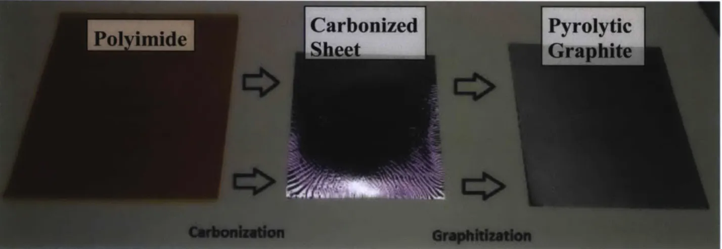
Figure 2: Progress of the raw polyimide material turning into its final graphitized product... 20
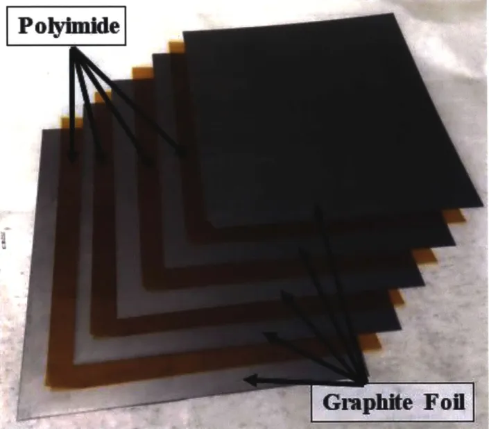
Figure 3: Sample of a stack of materials... 21
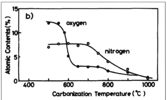
Figure 4: Changes of oxygen and nitrogen contents with carbonization temperatures [14]. ... 22
Figure 5: R ipples... 24
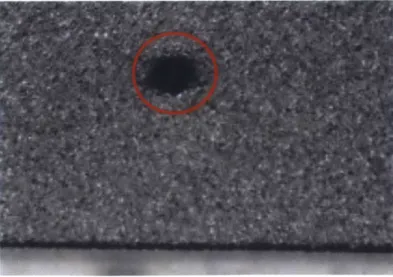
Figure 6: H ole ... 24
Figure 7: D ent ... 25
Figure 8: Spot... 25
Figure 9: Foreign Object Debris ... 26
Figure 10: Chromic Aberration... 26
Figure 11: Scratches... 27
Figure 12 : C racks... 27
Figure 13: Pictorial representation of the calender process [17] ... 30
Figure 14: Forces experienced by the top roll on a force-controlled machine where neither roll has been crow ned... 31
Figure 15: Forces experienced by the top roll on a displacement-controlled machine where neither roll has been crowned. The only forces in the nip are experienced by the sheet. ... 3 2 Figure 16: Roller misalignment [16]... 32
Figure 17: Result of a light roll force or a heavy crown [16] ... 35
Figure 18: Result of a heavy roll force or light crown [16]... 35
Figure 19: Result of a matched roll force and crown [16]... 36
Figure 20: Geometry of a sheet in a calender nip [17] ... 36
Figure 21: Measurement system with five Ames digital indicators (resolution of 2 microns)... 40
Figure 22: Mitutoyo high-accuracy digimatic micrometer (resolution of 0.1 microns)... 40
Figure 23: Results from a static nip impression test at various pressures. Note that the ends of the lines are thicker than the middle, which indicates a heavy roll force or light crown. 41 Figure 24: Example of a large wrinkle. The top of the sheet was inserted into the calender m achine first... 42
Figure 25: Two different methods to insert the heat spreader into the calender machine ... 43
Figure 26: A bubble on the post-calendered heat spreader... 44
Figure 27: Cooling loop of the thermal conductivity test apparatus... 50
Figure 28: One Side of the testing apparatus... 51
Figure 29: Thermal conductivity test setup ... 53
Figure 30: Placement of the material on the test apparatus ... 54
Figure 31: Run Chart for Thickness of Calendered Heat Spreaders... 55
Figure 32: Average thickness (top graph) and Control Parameters (bottom graph) for each trial run of the process control experiment... 58
Figure 33: Run Chart Experiment Result. 60 sheets were calendered on Day 1 and 5 sheets were calendered on Day 2. Rolls were cleaned after run 15. Control settings were not changed... 60
Figure 34: Thermal conductivity before and after calendering ... 61
Figure 35: Effect of the calender on ripples with unconverted areas ... 62
Figure 36: Effect of the calender on ripples with fully converted areas... 63
Figure 37: Effect of calender on a heavy spot ... 64
Figure 38: Effect of calender on a light spot... 64
Figure 39: Effect of calender on foreign object debris. In both cases, the foreign object debris caused bubbles to develop on the calendered material... 65
Figure 40: Effect of calender when foreign object is removed. There is no evidence of a foreign object on the calendered sheet ... 66
Figure 41: Effect of calender on scratch ... 67
List of Tables
Table 1: Average and Standard Deviation of Thickness with 45.4-mil Left Shim and 45.1 -mil R ight Shim ... 56Table 2: Average and Standard Deviation of Thickness with 44.9-mil Left Shim and 44.7-mil R ight Shim ... 57
Chapter 1. Introduction
This thesis examines how AvCarb Material Solutions, an advanced materials company, can improve the manufacturing process of its heat spreader production line as it prepares to scale up its production rate. More specifically, this thesis analyzes the addition of a calender machine to this production line and the experimental procedure that was followed to verify that heat spreaders were produced to specification. Moreover, potential improvements in production efficiency are examined by analyzing whether any defects that appear on the uncalendered heat spreader sheets still manifests themselves on the calendered sheets. And lastly, a test apparatus was built that measured the improvement in thermal conductivity of the calendered heat spreader.
1.1 Background and Company History
AvCarb Material Solutions was founded in February of 2013 when it was sold by Ballard Power Systems [1]. However, the existing factory has existed in some capacity at its Lowell, MA facility since 1964 and has manufactured a variety of advanced materials, most notably the heat shields for the Apollo space program. Currently, AvCarb specializes in carbon fiber materials for three main areas: friction applications (e.g., brake pads for automobiles), electrochemical applications (e.g., gas diffusion layers for fuel cells), and thermal applications (e.g., heat spreaders for the consumer electronics industry) [2]. The focus of this thesis is the manufacturing process of heat spreaders, or as it is more generally called, pyrolytic graphite sheets, that are thin, highly-flexible, and four times more thermally conductive than copper [2].
1.2 Industry Use for Pyrolytic Graphite Sheets
Pyrolytic graphite sheets are used predominantly in the consumer electronics industry in smartphones and ultrathin laptops for the purpose of moving heat away from
critical chips and microprocessors. As these electronic devices become smaller and thinner, a premium has been placed on the ability of these devices to shed off their waste heat in a manner that consumes less space. For large systems such as desktop computers, waste heat is removed through conduction via an aluminum or copper heat sink and by convection to the air. As the processing power on a desktop system is increased, the corresponding increase in waste heat is handled by adding a larger fan or heat sink. However, thin electronic devices do not have the luxury of extra space and cannot rely on air convection as the dominant means of internal heat transfer. If these devices cannot dissipate their waste heat in an effective manner, their critical components can be damaged. Thus, they rely on a class of advanced materials characterized by their high thermal conductivity, such as pyrolytic graphite.
Pyrolytic graphite is also used in other industries that manufacture products in which heat must to be moved through a thin space. The LED light industry relies on this material in order to run more current through its wires and keep its electronics cool for brighter lights [3]. This material is also important in the LED television industry where customer demand for increasingly thinner displays creates challenges for engineers who know that excess heat can permanently damage the image displayed on televisions. The fuel cell and battery industries also use pyrolytic graphite in order to cool their fuel cells and battery stacks, respectively [4].
In the commercial space, the overall driving factor of pyrolytic graphite sheets is the smartphone and laptop industries where thinness is a consumer premium. As the market grows for smartphones and laptops, the market for this material will grow accordingly. AvCarb is situated very well to potentially capture some of this growing market.
1.3 Research Motivation
AvCarb entered the pyrolytic graphite business in 2013 by successfully using its existing capital assets to make heat spreaders, as it is known at AvCarb. Now, AvCarb is in the process of not only scaling up its production of heat spreaders to meet the growing demand of the market but also adding a new production step to the end of its current production process in order to broaden its customer base. AvCarb's target is to produce in each month the same amount it produced in all of 2013.
There are four key steps to the production of heat spreaders: first, raw sheets of polyimide are interleaved with another material sheet called graphite foil to create a stack; second, multiple of these stacks are carbonized in a batch graphitizing furnace; third, the stacks are moved to an induction coil furnace where the raw polyimide is graphitized, creating the heat spreader product; and fourth, the heat spreader sheets are separated from the graphite foil sheets, inspected, and packaged for shipping. Recently, and particularly relevant to this thesis, AvCarb added a fifth step to its production line
-calendering, which was previously done by AvCarb's direct customer - in order to gain more control of the yield of the production process and to expand its customer base. This calendering step reduces the thickness of the heat spreader sheet via the application of pressure between two hard rolling cylinders and gives the final product its high thermal conductivity.
With such a large increase in production rate of heat spreaders, AvCarb faces a number of challenges in meeting this goal. One challenge is the long production lead time because of the time the heat spreaders spend in the two furnaces. Also, the heat spreaders share time in the furnaces with products from AvCarb's friction and electrochemical application lines. Therefore, the most effective way for AvCarb to scale-up production of its heat spreaders is to more efficiently use the time and space that is already scheduled
for heat spreader production. To accomplish this, AvCarb needs to develop a more complete understanding of how defects are formed during production, as well as methods of reducing those defects, which will increase AvCarb's production yield.
With the addition of a calender machine, AvCarb desires to automate the calendering process, which has three specific challenges: 1) integrating the machine into its existing production process; 2) ensuring that only sheets with negligible defects go through the calender machine; and 3) controlling the machine to produce heat spreader sheets at a desired thickness.
Each of these topics is explored in more detail as an individual thesis for the Masters of Engineering in Manufacturing Program at Massachusetts Institute of Technology. A group of three students worked with AvCarb Material Solutions to apply research techniques in manufacturing to these issues. Chase Olle focused on designing a material handling system that will connect the end of the AvCarb's current process with the new calender machine [5]; Yugank Chawla implemented a vision inspection system to detect the defect on the uncalendered sheets [6]; and Knute Svenson, the author of this document, focused on controlling the calender machine and determining which defects (identified by Chawla) are negligible. Figure 1 shows a basic schematic of how the combined projects of the three students will fit into a production line.
Visual inspection Ma Calendeig Sepind
PlacnantCa mStep 8:
Rewind
Figure 1 illustrates the new manufacturing process line that will be placed after the heat spreaders have been separated from the graphite foil. First, the heat spreader is picked up from a stack of finished product by a robot and moved to a vision inspection system, which scans for defects that may be missed by the previous inspectors. If the material has insignificant defects, it is placed on a polyester roll; otherwise, the material is discarded. The polyester roll transports the good material through the calender machine, where the sheets are reduced to a target thickness of 25 microns and rolled up for packaging.
The new calender production line needs to be automated because customers desire a minimal, repeatable gap between each sheet on the polyester film so that the customers' production system can reliably cut shapes in the sheets for the final end customers. The scope of the three projects was for the three students to solve issues related to the individual projects and make recommendations to AvCarb on further steps needed in order to combine the three parts.
1.4 Brief Background on Calendering Issues
At the introduction of this project, AvCarb sourced a low-cost calender machine for three reasons: 1) to obtain better control and understanding of the entire production line from raw material to final customer product; 2) to shorten the lead time to its current customer; and 3) to broaden the customer base since the calendered heat spreader has a higher value for a greater number of customers.
Before calendering was incorporated in-house, AvCarb would ship the uncalendered heat spreader material to its customer who performed the calendering step. One major issue arose with this arrangement. AvCarb's customer would sometimes reject wholesale orders of sheets because of a newly-identified defect, which has happened as much as to six months after receipt. Consequentially, all the heat spreaders produced
during those six months had to be reexamined to ensure they did not contain any of the same defects. Additionally, from the moment the heat spreaders are put into the furnace to the time they are unstacked, they cannot be examined. As a result, the first time AvCarb can know whether any defects have formed is after the product has gone through the entire production cycle. Therefore, AvCarb cannot be sure what part of the process causes certain defects.
By integrating a calender machine to its production process, AvCarb hopes to
receive immediate feedback about quality of the heat spreader sheets, which can be used to modify and improve the quality of its manufacturing process. Also, having its own calender machine gives AvCarb the freedom to experiment to determine which noticeable defects, such as a spot, on the uncalendered material are insignificant once the sheets have been calendered. If AvCarb can effectively determine which types defects become insignificant during the calender process, AvCarb can increase its yield of heat spreaders by not discarding any uncalendered heat spreaders prematurely.
1.5 Problem Statement
The main focus of this project and the thesis is the integration of the calender machine into the existing manufacturing process of heat spreaders. This thesis discusses the process of controlling the calender machine to produce heat spreaders at a thickness of 25 microns and presents the results of meeting this goal, including thickness and thermal conductivity measurements. Secondly, this thesis documents how the calender machine was used to examine whether any defects on the uncalendered sheets become insignificant upon calendering. And lastly, the thermal conductivity of the calendered and uncalendered heat spreader sheets are measured and compared.
1.6 Thesis Overview
Chapter 2 discusses the AvCarb's current manufacturing process and the materials used in the process. Chapter 3 provides detail on the physics and control settings of the calender machine. Chapter 4 describes AvCarb's current calender machine as well as the protocol used to ensure the machine produces material to specification. Chapter 5 discusses the design of a thermal conductivity measurement apparatus used to test the thermal conductivity of the heat spreader before and after calendering. Chapter 6 reviews the results of the both the process control experiment and the thermal conductivity experiment, and Chapter 7 covers the implications of these experiments and propose areas of further study.
Chapter 2. Materials and the Manufacturing Process
2.1 Overview
The first half of this chapter outlines the main materials in the production process
and includes an understanding of why those materials are used and their important material properties. The second half explores the manufacturing process performed at AvCarb to convert the raw materials into pyrolytic graphite sheets.
2.2 Polyimide Film
A polyimide film is the starting raw material that will be converted to a pyrolytic
graphite sheet. The term polyimide describes a general class of plastics that have high heat resistance and an amorphous molecular structure dominated by a backbone of hexagonal carbon rings; however, there are many different types, which are defined by their specific atomic structure and their manufacturing process. For AvCarb, this polyimide film is highly desirable as the precursor material for pyrolytic graphite because its chemical structure leads to a high carbon yield during the carbonization and graphitization process. As studies have shown, the molecular structure of the polyimide governs the structure of the final carbonized material [7]. The graphitizability of these polyimides largely depends on their in-plane orientation of their atomic bonds. Even a local difference in degree of bond orientation induces non-uniform graphitization, creating subpar graphite sheets [8].
As discussed later in the thesis, each type of polyimide can react differently in the production process of heat spreaders. More importantly, certain graphitized polyimides are less likely to generate defects as they are passed through the calender machine.
2.3 Graphite Foil Sheet
Graphite foil sheets are used between each layer of polyimide film and are a flexible sheets made using a powdered form of natural graphite. The powdered graphite flakes are treated chemically and exposed to heat, causing the flakes to expand. These flakes are then mixed with untreated graphite powder and compressed using a roller to form graphite foil sheets. These sheets are resilient, compressible, thermally stable, and have a high thermal conductivity [9].
Graphite foil provides three benefits during the pyrolytic graphite production process. First, the graphite foil separates individual polyimide films. If two polyimide films are in direct contact with each other during the carbonization stage, their surfaces will adhere and become difficult to separate. Second, the thermal conductivity of the polyimide film is low (0.37-[) [10]; therefore, the graphite foil is used to maintain thermal
mK
uniformity across the polyimide films during the heat treatment steps. Third, the graphite foil compresses the polyimide films in the stack, keeping them flat. Without this compression, the polyimide sheets will wrinkle and warp during the carbonization phase.
2.4 Pyrolytic Graphite Sheet
Pyrolytic graphite sheet are what the polyimide films are converted to after the graphitization step. These sheets are thin, lightweight, and have high in-plane thermal conductivity compared to common metals such as copper. Because of their high thermal conductivity, pyrolytic graphite sheets are used to diffuse waste heat generated in electronic devices such as CPUs, power amplifiers, cameras, and mobile phones [11].
The thermal properties of pyrolytic graphite are the result of its atomic bonds. High-energy bonds dominate the lattice in the in-plane direction resulting in very high
thermal conductivity (>1500 -) [2]. These high energy bonds are formed because of the
in-plane orientation of the starting polyimides' hexagonal rings. However, these sheets
are anisotropic and have much lower thermal conductivity (~10-w::) in the cross plane
mK
direction because of the weaker Van der Waals interactions between atoms.
2.5 Overview of the Manufacturing Process
In this section, the process of manufacturing the heat spreader is discussed, including a brief discussion of the physics and chemistry of each process. At AvCarb, the polyimide film goes through four key manufacturing steps: stacking, carbonization, graphitization, and unstacking. After these steps, the material goes through the calender machine, which is the subject of Chapter 3.
Figure 2: Progress of the raw polyimide material turning into its final graphitized product
2.5.1 Stacking
In the stacking process, workers manually interlayer the polyimide and graphite foil sheets into a stack. Workers typically wear gloves and masks during this procedure to avoid depositing foreign objects onto the polyimide film. Each stack can contain over
I
PoyImke
Figure 3: Sample of a stack of materials
2.5.2 Carbonization of Polyimide Film
Next, the stacked material is moved into the first furnace where polyimide films are carbonized, or converted into roughly 99% carbon by weight. This step occurs at temperatures above 1000'C in order to boil off non-carbon atoms, such as oxygen and nitrogen. Figure 4 shows a graph of the atomic concentration of oxygen and nitrogen on polyimide films decreasing with temperature.
-
b)
400
0
800
10
Carbordegtfon
Tempacture
VC)
Figure 4: Changes of oxygen and nitrogen contents with carbonization temperatures [141.
Next, the furnace is turned off, and the material is allowed to cool to room temperature. Then, a vacuum exhaust duct is used to evacuate residual toxic gases, such as hydrogen cyanide (HCN) that have formed during production. Then, the stacks are moved to the induction furnace room where the graphitization step happens. The carbonized material (see Figure 3) is shiny, fairly rigid, and has a granular, glass-like carbon structure [12].
2.5.3 Graphitization of Polyimide Film
In the graphitization step, the material is moved to an induction coil furnace, where it is heat treated in excess of 2500'C under atmospheric pressure in an inert gas environment and held at temperature [13]. This heat treatment step rearranges the molecules of the carbonized sheets into highly-crystalline and highly-oriented structures
by changing the bonding pattern of the carbon atoms. The resulting graphite films are
After graphitization is complete, the furnace is shut off and is allowed to cool to room temperature. Then, the material is moved to the unstacking area. The thickness of the graphitized sheet increases by 50% over the carbonized material and the length and width of the sheet increases by 9-18% as a result of the wrinkles on the carbonized sheet flattening out during graphitization [14].
2.5.4 Unstacking and Inspection
After the material is moved into the unstacking room, workers manually separate the pyrolytic graphite sheets from the graphite foils into separate stacks. As the workers unstack the sheets, they inspect the quality of both the graphite foil and the pyrolytic graphite sheet. Graphite foil free of defects is placed into one stack to be reused for the next production cycle; graphite foil with defects is placed in another stack to be discarded. Each graphite foil sheet can be reused many times before it becomes too brittle or weak. The pyrolytic graphite sheet is also separated into two piles: one of good material (those with minimal visual defects) and one of bad material (those with a visual defect, such as ripples, spots, and chromic aberration).
Then, the workers take thickness measurements of representative samples at different depths of the stack (equally spaced from top to bottom) to ensure the pyrolytic graphite sheets meets their thickness specification. The target thickness specification for the material at this stage is between 60 and 90 microns.
Finally, the pyrolytic graphite sheets are wrapped, vacuum-sealed, and shipped to AvCarb's customer, who will calender the sheets, which is the subject of Chapter 3.
2.5.5 Types of Defects
In AvCarb's visual inspection phase, the workers generally look for eight common types of visual defects that can be detected with the human eye.
1. Ripples - A wave-like pattern found on the edges of a sheet caused by creases that
form during the carbonization step. In certain cases, ripples can persist through the graphitization step. If ripples have depth or protrude more than two millimeters from the edge, the sheet is discarded.
Figure 5: Ripples
2. Holes - A perforation through a sheet caused by hard particles trapped inside of
the stack of material during the carbonization and graphitization steps. In some cases, the particle can puncture the sheet, leaving a hole. If visible light can been seen through a hole, the sheet is discarded.
Figure 6: Hole
during heat treatment, then the particle can create dents on sheets stacked above that sheet. The area of the dent is fully converted to graphite but is slightly thicker than the surrounding sheet. Sheets with dents are discarded.
Figure 7: Dent
4. Spots - Tiny circular dots that appear on the product. Unlike dents, these dots represent unconverted material, which means that the local surface was not fully converted to graphite. Spots are usually the result of particulate matter that has deposited on the polyimide film during heat treatment. Spots usually have no thickness difference with the rest of the sheet. A sheet is acceptable as long as it has less than a certain number of spots smaller than 3 mm in diameter.
5. Foreign Object Debris - Irregular shaped defects that occasionally contain a particle embedded in the center. These particles come from graphite flakes breaking off during the heat treatment process and leave an elongated mark on the surface of a sheet. Any sheet with foreign object debris is discarded.
Figure 9: Foreign Object Debris
6. Chromic Aberration - A large area of not fully converted material, which forms an
area of discoloration on the surface. This defect may be the result of impurities within the graphite foil. Chromic aberration can also be detected with a thickness gauge since the area of unconverted material will be thicker than the converted areas. Any sheet with chromic aberration is discarded.
7. Scratches -Line marks on the surface caused by either human factors or the heat
treatment process. When the polyimide shrinks and expands during the carbonization and graphitization process, small defects on the graphite foil can scratch the surface of the polyimide. Similarly, if a worker does not carefully lift the graphite foil from the finished product but instead slides the foil away, he or she will cause a scratch on the material. Scratches are generally not acceptable; however, if the scratch is small and faint enough, the sheet may be acceptable.
Figure 11: Scratches
8. Cracks - Small tears on the edges of a sheet that are the result of improper handling.
If a sheet is torn, then the sheet must be discarded. Also, if a sheet is not laid flat
in the stack at the start of the heat treatment process, a crease will form.
The exact criteria for what is and is not an acceptable defect is a subjective guideline based on an agreement between AvCarb and its customer, and AvCarb's customer learns about acceptable defects from its downstream customer. Thus, the final authority on the acceptability of defects is the end customer. However, the motivation for AvCarb's customer is to not waste valuable production time on material with questionable defects, so the customer is unwilling to experiment with these questionable defects and errs on the side of caution when labelling defects (see Chawla for more information on the identification and acceptability of defects [6]).
However, with its recently-purchased calender machine, AvCarb can afford to conduct trials to see the effects of the calender machine on certain defects. As part of the validation stage of this project, some defects (ripples, foreign object debris, spots, and scratches) were run through the calender machine. Some defects, such as holes and cracks, already represent a destruction of the sheet and cannot be saved by the calender machine; therefore they were not tested for this project. Dents and chromic aberration were not tested since an adequate sample size was not obtained for either defect.
For this project, AvCarb had been setting aside defective sheets from its production process for this experiment. These defective sheets were categorized by their respective defect(s). Sheets with multiple defects were categorized by the rarest defect. Each defect had a sample size of more than twenty sheets; therefore, each defect category was calendered more than twenty times for repeatability purposes. Since there was not a direct line of communication to the direct end customer, who has the final say of whether a defect is acceptable or not, this experiment did not attempt to determine the acceptability of a calendered defect. However, if a defect caused a hole or a tear, then it was determined that the sheet can be rejected. The results of this experiment are found in Section 6.4.
Chapter 3. Calendering
3.1 Overview
This chapter will give a brief introduction on the topic of calendering as it relates to thin films. It details the basic physics of calendering and describes the common control methods used to modify the calendering process. These methods are important to understand in order to follow the experimental process used to bring the output of AvCarb's calender machine within specification.
3.2 Calendering Basics
A calender machine reduces the thickness and surface roughness of a paper or thin
film to a specified thickness by plastically deforming the material between two or more cylindrical rolls in order to achieve a reduced thickness (see Figure 13). Calendering is usually the final step in the manufacture of many types of paper or thin sheets and, hence, will be the final step in AvCarb's manufacturing process. Usually, as is the case for this project, the rolls can be hard and applies a higher force over a smaller area; but in other applications, such as rubber forming, the rolls are soft, which creates less pressure and a larger contact area. For the heat spreader material, the main measurable outputs of the calender machine are the thickness, the uniformity of that thickness, the presence of any defects, and the thermal conductivity.
Figure 13: Pictorial representation of the calender process [171
3.3 Methods of Controlling Thickness
In order to control the thickness output of the calender machine, a few parameters can be changed, including adjusting the downwards force applied by the rolls (force control), physically adjusting the gap between the rolls, known as the nip (displacement control), altering the rotating speed of the rolls, or modifying shape of the rolls (known as the crown). Other properties, such as web temperature, moisture content, and roll diameter, also has an effect on the final thickness [15], but these variables are not explored in this chapter.
3.3.1 Force Control
A force-controlled machine uses the roll force as the major method of adjusting the
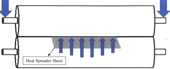
pressure distribution in the nip. Roll force is typically applied via hydraulic cylinders to the ends of the top roll. This force is transferred to any sheet inserted into the nip and plastically deforms that sheet to a smaller thickness in accordance with the mechanical properties of the material. Ideally, the pressure distribution created by this force is uniform across the entire length of the nip so that the output sheets is of uniform thickness. Figure 14 shows a schematic of the forces experienced by the top roll under force control; the arrows indicate the relative magnitudes of the forces. In the diagram,
Heat Spreader Sheet
Figure 14: Forces experienced by the top roll on a force-controlled machine where neither roll has been crowned
The final thickness of the material is a function of the starting thickness, the elastic modulus of the material, and the roll force. The higher the roll force, the greater the strain experienced by the sheet, and the thinner the output material. However, the input heat spreader material from one stack at AvCarb can vary in thickness by up to 16 microns; therefore the roll force would have to be constantly adjusted to ensure a consistent output thickness, which makes force-control not a good strategy in this case.
3.3.2 Displacement Control
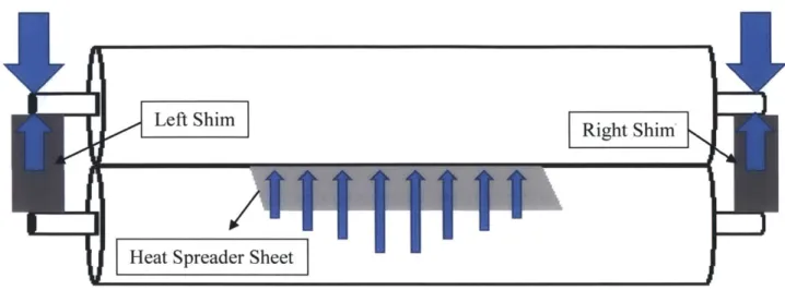
The alternative to force control is to control the displacement of the rolls to maintain a fixed nip gap. For AvCarb's calender machine, mechanical stops at each end of the rolls were used to control the displacement, and the height of these stops was adjusted with the use of shims. In this case, the shims will bear all of the hydraulic cylinder roll force as the sheet is inserted into the nip (see Figure 15). In this case, the fixed nip gap ensures the output material reaches its target thickness, and using shims helps to modulate the amount of force that is transferred to the sheet. If the input sheet is thicker, then the sheet will experience a greater force and a greater strain; if the input sheet is thinner, then the sheet experiences less of a force and less strain. Also, using different
shims on the left and right side allows small corrections to be made in the roll alignment (see Figure 16 for an exaggerated picture, [16]).
14
Left Shim
Heat Spreader Sheet
Figure 15: Forces experienced by the top roll on a displacement-controlled machine where neither roll has been crowned. The only forces in the nip are experienced by the sheet.
Location of Left Shim Location
R
= of Right ShimFigure 16: Roller misalignment [16]
For example, in Figure 16, the left side gap height is much narrower than the right side, which will result in the output material to be thinner on the left side than on the right. To correct this situation, either a taller shim must be placed on the left side, or a smaller shim must be placed on the right side. The former solution is used if the average thickness of the entire sheet is less than the target thickness; whereas the latter situation
PfrI
INot only is the gap height affected by the shims, but it is also affect by the hydraulic pressure that applies the roll force. At the typical pressures experienced in the calender machine, the shims can be modelled as two springs with a very high spring constant. That is, as the roll force is increased, the shims can compress a small yet significant amount. Usually this compression can be ignored; however, in AvCarb's case, the calender machine's output has a thickness tolerance of 4 microns. Calculations using Hooke's first law can show the significance of this compression.
FL
+
FR= kL-XL + kRXR (3.1)where k is the stiffness of the shims, x is the distance the shims compress, L means left side, and R means side. The stiffness, k, is related to the material's modulus of elasticity as thus:
ki = A1E1 (3.2)
Li
where A is the cross sectional area of the shim, E is the modulus of elasticity, and L is the length of the shim. Since both shims are made of stainless steel and force on the left side should be equal to the right side, only one side needs to be considered. Thus, the equation simplifies to:
F E (3.3)
=
XFor stainless steel, the modulus of elasticity (E) is 26.1 x 10⁶ psi, the length of the
shims is 2.38 inches. Thus, for a pressure of 285 psi, which is the low end of the calender machine's typical operating limit, each shim.will deflect 0.66 microns. On the high end of the pressure (~1280 psi), each shim can deflect approximately 2.96 microns, a difference of 2.3 microns. This difference is significant relative to the tolerance band of 4 microns;
thus, adjusting the pressure along with the shims can be used to fine adjustments to control the process output.
3.3.3 Speed of the Rolls
The speed of the rolls will determine how fast the sheet moves through the calender machine. Decreasing calender speed results in longer nip dwell times and decreased thickness of the material [17]. The speed of the rolls will also dictate how fast the polyester web system is moving through the production line and affects the material movement and visual inspection stations. The speed of the calender machine was not adjusted for this project and kept at 2 m/min.
3.3.4 Shape of the Rolls
Lastly, the crown of the rolls can have a significant effect on the output. A crown is a very slight thickness increase in the middle of the rolls that will allow the rolls to create a uniform pressure between them when they bend under load. The crown corrects for the deflection of a roll that happens with a sheet is inserted into the nip. In that case, the sheet will exert a force opposing the roll force of the calender, causing the rolls to bend away from the sheet and creating an uneven pressure distribution. A crown is cut into the roll depending on the length of the roll and the expected pressure of operation. However, the crown of the rolls is set once the roll is made and cannot be adjusted. Also, once a roll is crowned, the operational pressure cannot deviate significantly from the original target, otherwise the nip pressures will be uneven as seen in Figure 17 and Figure
18. Figure 17 shows the case where the crown is too heavy for the roll force used. In this
case, the pressure experiences in the nip will be at a maximum in the center of the roll. Material calendered under this condition will be thinner in the middle than on the left and right edges.
Figure 17: Result of a light roll force or a heavy crown [161
Figure 18 shows the case where the crown is too light for the roll force used. Here, the rolls bow out from the middle, which causes the pressure in the nip to be at a maximum near the ends of the roll. Material calendered under this condition will be thinnest near the left and right edges than in the middle.
Figure 18: Result of a heavy roll force or light crown [16]
In Figure 19, the crown of the roll matches the roll force. Here, the pressure distribution is uniform across the entire length of the nip. This is the ideal setting to ensure that the calendered material has a uniform thickness.
I
I
Figure 19: Result of a matched roll force and crown [16]
3.4 Physics of the Compression in the Calender
Figure 20 shows the geometry of what happens as the material comes into contact with hard roll. The paper starts off at a uniform thickness bin, then is reduced to bmin before it springs back to its final thickness bp. There are many models that attempt to describe and predict the output (6p) based on the other parameters in the figure [17].
Calender Ro
Empirical models developed by Chapman and Peel modelled this process as a logarithmic function of maximum pressure and pulse duration [18]. Kerekes developed another empirical model that examined the effects of nip load, roll radius, and machine speed [19]. Haglund and Robertson modified Chapman and Peel's empirical model to include a factor that accounts for the ratio of the starting density of the sheet to the maximum obtainable density in the calender nip [20]. Crotogino combined these models into a comprehensive equation [21]:
EP= A + gBi (3.4)
where E, is the permanent bulk reduction (or reduction in thickness), A is a constant, Bi is the initial bulk, and t is defined by:
p = ao + aL log L + as log S + a log R + a0e + aMM (3.5)
where ao, aL, as, aR, a6, and aM are empirical constants, L is the nip load in kN/m, S is the
machine speed in m/min, R is the roll radius in meters, 0 is the paper temperature in 0C,
Chapter 4. Integrating the Calender Machine
4.1 Overview
This chapter will discuss the integration of AvCarb's calender machine, including some of the physical specifications of the machine, the process of troubleshooting its initial setup, and methods used to eliminate common errors.
The target for the calender machine is to produce heat spreader sheets that are uniformly 25 microns thick with minimal visual defects. This chapter will also discuss the protocol followed to determine the control parameters of calender machine in order to achieve this goal.
4.2 Description of AvCarb's Calender Machine
AvCarb purchased a used calender machine for exploratory purposes. The bottom roll is stationary, and the top roll moves up and down via hydraulics, which regulates the roll force. The top and bottom rolls are connected by two gears, which enables them to rotate at the same speed. The bottom gear is driven by a chain from a speed reducing gearbox, which, in turn, is driven by a belt from a drive motor. Shims are added to the left and right stops between the two rolls. Standard AA-sized slotted shims were used for fine-tuning adjustments.
The roll force and the speed of the rolls are controlled through a touch screen mounted on the front of the calender machine.
4.3 Initial Installation Steps
power supply, and all functionalities (hydraulics, motor, lights, etc.) were tested to verify that the machine was in working order. Then, informal experiments were conducted to analyze the quality of the calendered sheet and to identify any common errors. Three main issues were identified in these early trials, 1) deviations in thickness, 2) appearance of wrinkles, and 3) appearance of bubbles. The following subsections will discuss these issues and the methods used to correct them.
4.3.1 Deviations in Thickness
The target thickness for the calendered heat spreader is 25 4 microns. Additionally, the thickness of the left and right sides of the heat spreader cannot differ
by more than 2 microns. For this project, the thickness of the heat spreaders were
measured with two separate devices: an Ames AQD-2110N-2-1/2X digital indicator (with a resolution of 2 microns, see Figure 21) and a Mitutoyo high-accuracy digimatic micrometer (with a resolution of 0.1 microns, see Figure 22). The Ames digital indicator is used to measure the thickness of samples of the uncalendered sheets during the inspection phase. The digital indicator measures the thickness at five points on the sheet: each of the four corners and the center. However, given the sensitivity of the target range of the calendered sheets, the Mitutoyo micrometer was also used for its high resolution. This device only takes one reading at a time but was used to measure the thickness of the four corners of each sheet.
Figure 21: Measurement system with five Ames digital indicators (resolution of 2 microns)
Location of Sheet
't
'm
Figure 22: Mitutoyo high-accuracy digimatic micrometer (resolution of 0.1 microns)
Any errors in thickness in the calendered heat spreader stems from the pressure profile in the nip, which is a function of the height of the shims, the roll force, and the amount of crowning in the rolls. Because this calender machine had not been directly sourced by AvCarb, data on the crowning of the rolls was not available. Thus, to detect how much the rolls were crowned, nip impression paper was used. Nip impression paper
the color change corresponds to a heavier pressure. Nip impression paper can also be used to determine the width of the pressure distribution. To set up the test, the shims were removed from the calender, and the nip impression paper was set up across the entire length of the nip. Then, the calender machine was manually operated to close the gap (without turning the rolls) and held for 5 seconds. This procedure was repeated for pressures between 350 psi and 920 psi in order to determine at which pressure was the
distribution even. The results of this experiment are shown in Figure 23.
Pressure
High Pressure Low Pressure
350 psi 500 psi 640 psi
780
psi
920
psi
Right SdFigure 23: Results from a static nip impression test at various pressures. Note that the ends of the lines are thicker than the middle, which indicates a heavy roll force or light crown.
Figure 23 shows that the roll force is non-uniform at all pressures for the given crown because the width of the red line is thicker at the ends then in the middle. Additionally, a thicker line denotes a region that experienced high contact pressure, and a thinner line denotes a region that experienced a low contact pressure. At lower pressures, the width of the line is most uniform; therefore, the pressure that matches the crown occurs at a pressure lower than 350 psi. Since 350 psi is at the low end of the calender machine's operating capability, shims were used to help even the pressure distribution in the nip. Section 4.4 will discuss the process used to determine what size shims should be used, and Section 6.2 will show the results of the process.
4.3.2 Wrinkles
Wrinkles are a destructive defect found on the sheet after it has gone through the calender machine. Usually wrinkles will form once the sheet has gone halfway through the calender. These defects appear as a branched pattern from the middle of the sheet to the end, as seen in Figure 24. A sheet that has any wrinkles is rejected.
Figure 24: Example of a large wrinkle. The top of the sheet was inserted into the calender machine first.
Wrinkles are a function of the local variations in pressure along the nip, the manner in which the material is inserted into the machine, the build-up of pyrolytic graphite flakes, and the polyimide lot of the material. Local pressure variations could cause the sheet to shear slightly. These non-uniform pressures can be examined using the aforementioned nip impression paper and corrected by adjusting the shims.
Another way of controlling the appearance of wrinkles is the insertion method used to feed material into the calender machine. Placing the sheet flat on the bottom roll
from forming as opposed to feeding the sheet directly into the nip ("direct insertion"). Figure 25 shows an image of the two methods. The roll insertion method helps ensure that the leading edge of the sheet is perfectly flat on the roll. When it is fed directly into the nip, the sheet's leading edge can buckle slightly and cause the rolls to pinch the material, creating wrinkles.
a) Direct Insertion
b) Roll Insertion
Figure 25: Two different methods to insert the heat spreader into the calender machine
A build-up of pyrolytic graphite flakes on the calender roll can cause wrinkles as
well. After many sheets have been calendered, small bits of the calendered sheets will adhere to the roll affecting its smoothness. Therefore, the rolls occasionally need to be cleaned with isopropanol to remove those flakes. The frequency of cleaning will depend on whether the sheets that have been calendered have developed wrinkles or not. The calender machine may have to be cleaned after one sheet if that sheet has a significant wrinkle, as seen in Figure 24. Finally, some sheets are more likely to develop wrinkles even if the pressure is uniform and the roll is clean. In this case, switching the starting
material to a new polyimide lot is the only solution that was discovered, but it is not certain why.
4.3.3 Bubbles
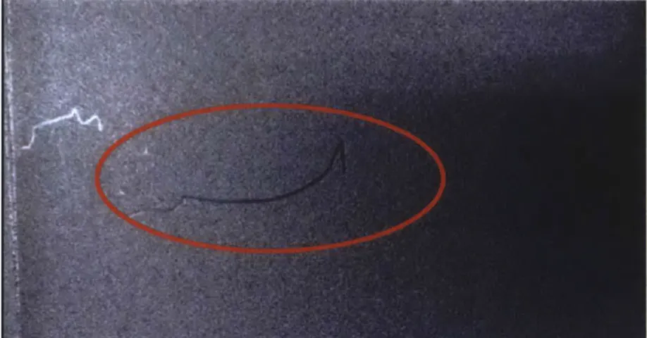
Lastly, the calendering can cause bubbles to form on the final material. A bubble
is different than spots found on the pre-calendered material, as highlighted in Section
2.5.5. These bubbles are usually approximately 2-4 mm in size and are occasionally accompanied by a faint horizontal white line (see Figure 26). These bubbles are mainly the result of foreign object debris that is deposited on the sheet's surface. Some foreign objects are noticeable, and the location of the bubble can be predicted. Other times, a bubble can appear with no identifiable foreign object. It is unclear whether the foreign object was too small to be noticed or if a small particle was deposited on the sheet just before entering the calender machine. Bubbles can be avoided by carefully inspecting both sides of the sheet for any foreign objects and removing them or cleaning the calender machine.
4.4 Procedure for Reaching Target Thickness
The goal for the calender machine is to consistently produce sheets at 25 microns with no wrinkles or bubbles. Since this calender machine will eventually be part of a continuous automation line, it must perform this task reliably without the need for small adjustments as the line is running. The great challenge is that the same control settings on the calender machine may not work from one day to the next because of macro factors such as the temperature and humidity of the room and lot-to-lot variation of the polyimide; therefore, for each new production run, the control settings may need to be changed so that the machine can continue to meet its target specifications. Essentially, the goal for this procedure is to maximize the process capability of the calender machine using a one-factor-at-a-time method. The basics of the procedure is:
1) Calender three to five sheets under a given control settings.
2) Measure the four corners of each of the calendered sheet and record the data.
3) Based on the average result of the data and knowledge of the theory of calender
machines, adjust the control settings. 4) Repeat steps 1-3 until the target is reached.
In step 3, there were many individual decisions that could be made. The first task in this procedure was to balance the thickness on the left and right side of the sheet. If the difference in thickness was greater than two microns, then shims were added to or removed from the left or right side.
Next, the average thickness of the entire sheet was examined. If the average thickness was less than 25 microns, then either the roll force was decreased or equal thickness shims were added to both sides. Which alternative is best depends on how the thickness of the middle of the sheet compares to the edges. If the middle of the sheet is noticeably thicker, then that is an indication that the roll force is too low for the crown in
the roll. Likewise, if the middle of the sheet is thinner than the edges, then the roll force should be decreased. Once the thickness was in good statistical control, wrinkles and bubbles were eliminated by rolling the sheets into the nip and cleaning the roll when needed. Section 6.2 shows the result of following this procedure.
Chapter 5. Thermal Conductivity Test Apparatus Design
5.1 Overview
The heat spreader material achieves its high thermal conductivity coefficient
(>1500 ) after the calendering step. Following the installation of the calender machine,
mK
AvCarb sought to conduct experiments that would accurately measure this increase in thermal conductivity. To facilitate this goal, a device was designed and set up under the guidelines that an existing factory worker could operate the equipment and would provide a result within a reasonable margin of error. This chapter will discuss the theory behind the testing apparatus, discuss the design, and lastly go through the procedure of conducting an experiment. Both the calendered and uncalendered sheets were tested using this device.
5.2 Equations of Heat Transfer
The basis of the design was to measure the thermal conductivity of a narrow rectangular strip of heat spreader material using a constant heat source (a power resistor) on one end and a constant temperature sink on the other end (ice water). By surrounding this basic design within a very good insulator, the heat can be assumed to travel from the source to the sink only by conduction through the rectangular strip, which follows Fourier's Law:
aQ AT (5.1)
where 2 is the rate of heat input to the material, k is the thermal conductivity of theat
material in question, AT is the temperature difference between the hot and cold sides of the material, A is the cross-sectional area of the strip, and L is the length of the material
The cross-sectional area (A) and the length (L) are easy to control (by cutting the heat spreader material to length) or to measure with a caliper. The heat source (
)
was generated by a power resistor, which converts the electric power into heat in a predictable manner using Joule's first law:p = I .V __ (5.2)
where P is the amount of electrical energy converted into heat by resistor, I is the current going through the resistor, and V is the voltage drop across the resistor. Next, Ohm's Law will determine the amount of current (I) going through a resistor given the voltage (V)
and the resistance (R):
V (5.3)
R These two equations can be combined to form:
V2 (5.4)
R
Then, Fourier's Law (Eqn. 5.1) can be altered for this application to be:
V2 AT
(5.5) = kA
-R L
Therefore, by controlling V, R, A, L and measuring AT, the thermal conductivity (k) of the material can be calculated.
5.3 Design and Specifications of the Testing Apparatus
To start the design process, two power resistors were chosen as the constant heat input and ice water as the constant temperature heat sink. The power resistors also
across the entire width of the heat spreader. The power resistors chosen were 2.5 inches wide. The heat spreader strips were cut to a width of 2 inches so that there was room for error regarding the placement of the strip on the power resistor.
Next, preliminary calculations were performed to determine the resistance of the two resistors. To start, a 12-volt constant voltage power supply was selected to supply power to the resistor. Then, using Equation 5.6 below, the resistance was determined by choosing reasonable numbers for the other variables. 1650 - was used for thermal
MK
conductivity coefficient (from specifications for pyrolytic graphite sheet); the area was calculated to be 1.27x10⁻⁶ m2 (or 2 inches by 25 microns, the target thickness of the
calendered heat spreader). The length, L, was 9 inches or approximately the full length of the heat spreader sheet, and AT was estimated to be 100'C. 2R is used in this equation instead of R for the two power resistors in the design. Using these values:
(1650 V))2inw 1o0*C (5.6)
(12 2R V)2 ( -w (1.27x10⁻⁶ M2) -(
mKi 0.267 m
the minimum resistance, R, is approximately 92 Ohms, or a heat output of 0.78 Watts from the two resistor. However, it was determined that 0.78 Watts was not enough heat to accurately perform a thermal conductivity test of one sheet. The heat transfer between the thermal insulation (which was normally at 250C) and the ice bath (0*C) overwhelmed
the heat transfer between the power resistor and the ice bath. Thus, adding multiple layers of heat spreader strips allowed for a higher heat input from the resistor because of its larger cross-sectional area. Two 10-0 resistors, which would input 7.2 Watts, were chosen based on availability. Usingiquation 5.6, it was found that ideally the stack of heat spreader strips would t to be abou 230 microns (or 9 sheets).
For the constant temperature heat sink, ice water was circulated through a copper block via vinyl tubing. Ice water can be kept at a constant 00C temperature as long as ice
exists in the water. The ice bath was placed in an insulating cooler and pumped through vinyl tubing to copper blocks by a simple aquarium water pump. Copper blocks were cut to size of approximately 1-inch x 2.5-inch x 0.5-inch, and a -inch hole was drilled down the longest length of the blocks. The copper blocks also provided a large thermal mass which prevented the block's temperature from fluctuating from 00C during the