Design of composite sway building frames for global instability
47
0
0
Texte intégral
(2) This paper presents the numerical and analytical studies carried out at Liège University, as part of above European project, with the objective to investigate the behavior of sway composite structures under static loading. Particular phenomena put into sight through different analyses are illustrated herein. The actual response of the beam-to-column composite joints may be easily integrated into the described design and analysis procedures (Jaspart 1991); this specific aspect is therefore not addressed in the paper.. Introduction Most composite structures are laterally restrained by efficient bracing systems, such as concrete cores. This practice does not favor the use of composite structures. Indeed, once concrete construction companies are involved into major parts of a building, the reason for using composite structures for subsequent parts is often questionable. Moment resisting frames offer a flexible solution to the user of the buildings, especially for the internal arrangement and the exploitation of the buildings. When sufficient stiffness and strength with regard to lateral forces are achieved, such frames offer a structural solution, which can resist lateral loads. In seismic regions, properly designed moment resisting frames are the best choice regarding the available ductility and the capacity to dissipate energy. This is stated in Eurocode 8 devoted to earthquake engineering in which high values of the behavior factor are recommended. These frames are prone to secondorder effects; the latter have to be predicted carefully because they may govern the design. First investigations in this field have been carried out; in particular, the applicability of the wind-moment method to unbraced composite frames was first examined in a Ph.D thesis submitted at Nottingham University (Hensman 1998). As far as the European codes are concerned, Eurocode 4 ENV 1994, which deals with composite construction under static loading, contains design procedures for non-sway composite buildings only and gives design rules for composite slabs, beams, columns and joints. That is why a research project on global instability of composite sway frames has been. 2.
(3) funded by the European Community for Steel and Coal (ECSC). The objective of this project was to provide background information on the behavior of such frames under static and seismic loads and to provide simplified design rules. In the meantime, the decision has been taken to extend the scope of Eurocode 4 to sway frames and first rough guidelines are presently included in the so-called Eurocode 4 prEN 1994 version (not officially published document). In the present paper, numerical investigations conducted at Liège University on composite buildings under static loading are described. Also, the applicability, to composite sway frames, of simplified analytical methods used for steel sway frames is investigated. First, the available data relative to actual sway composite buildings are briefly commented on. Then, 2-D composite sway frames are taken out in order to perform numerical investigations. A benchmark study is first realized on 2-D frames; it aims at validating the applicability of the non-linear homemade FEM software FINELG to above structures before starting numerical analyses. Then, the latter are presented. Finally, it is shown how simplified analytical methods, initially developed for steel buildings, may be applied to composite sway buildings. Obviously, the application of these design procedures to composite sway structures requires, as a preliminary step, the derivation of the beam, columns and joint properties by means of appropriate analytical procedures: -. effective beam widths in hogging and sagging regions,. -. flexural stiffness and resistance of beam and column elements, including concrete cracking effects;. -. moment-rotation curves for structural joints;. -. …. The derivation of these properties is not part of the present paper and reference will be made to Eurocode 4 for their evaluation. Problems related to concrete time-dependent effects will also not be addressed.. 3.
(4) Data on existing buildings Existing buildings in which sway effects are likely to occur under static loading have been selected. The difficulty in this task was to collect, for each building, enough data such as those on geometry, material properties and joint detailing; these ones strongly influence the global structural response. These structures are briefly described below; more details are given later on.. “Ispra” building This 3-D full-scale building has been tested in Ispra (Italy) in seismic conditions. Tests on isolated joints have been performed so as to get the actual properties of the constitutive structural joints; however, the experimental results are not yet available. Two different configurations of this structure have been considered within the project: they aimed at resisting respectively static loading and seismic loading (Demonceau & Jaspart 2002b and Braconi, Camarelli & Salvatore 2001). Only the investigations performed on the first configuration are developed herein.. “Bochum” building It is a 2-D full-scale structure tested in Bochum (Germany) under static loading (Kraus 2002). Also tests on joints in isolation have been performed but the relevant experimental results are not yet available. The structure has been designed at Liège University so as to fail by global in-plane instability (Demonceau & Jaspart 2002a) (see results presented later on).. “U.K.” building The “U.K.” building has been tested at BRE (Building Research Establishment), U.K. The test report is well documented (yield strengths, dimensions, type of loading); in particular, the behavioral curves of the structural joints are given (see Li, Moore, Nethercot & Choo 1996a and 1996b).. 4.
(5) This building is the one used for the benchmark study.. “Eisenach” building This structure is an unbraced factory building erected in Eisenach (Germany). Numerical studies have been carried out with data obtained by courtesy of ARCELOR Group (formerly ProfilARBED Division).. “Luxembourg” building This is a bank office building located in Luxembourg (Grand-Duchy of Luxembourg). Numerical studies have been carried out on this structure and relevant data have also been kindly provided by ARCELOR Group.. Validation of the FINELG software In this section, a benchmark study aimed at validating the use of several finite element software for the numerical simulation of the non-linear behavior of composite structures is briefly described. The interested reader will find more details about this benchmark study in (Demonceau & Jaspart 2003). The ECSC partners involved in the numerical studies are the following: -. RWTH Aachen (Germany) – DYNACS software;. -. Pisa University (Italy) – ADINA 7.5 software;. -. Liège University (Belgium) – FINELG software. FINELG is a geometrically and materially non-linear finite element software developed. at Liège University (M&S Department) and especially used for research purposes (FINELG user’s manual 1999). It enables to follow the behavior of a structure up to the ultimate and even beyond. The reference structure for the benchmark study is the “U.K.” building because both the detailed data and test results were available (Li, Moore, Nethercot & Choo 1996a and. 5.
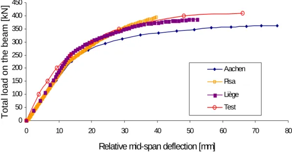
(6) 1996b). The validation is subordinated to a successful comparison of the results obtained numerically by the above partners with the ones recorded during the tests. The structure (Fig. 1) is composed of two parallel two-storey two-bay main frames (namely “Frame A” and “Frame B”) connected by secondary beams. The bare steel columns support floors consisting in composite slabs; the latter are connected by shear studs to the top flanges of the sole primary beams. Though the reports (Li, Moore, Nethercot & Choo 1996a and 1996b) are well documented, some data are nevertheless missing; therefore reasonable assumptions (Demonceau & Jaspart 2001) have been agreed on so as to ensure a complete similarity of the data used by the above partners for performing their respective numerical simulations. In Frame A, all the columns are bent about their major axis, while they are about their minor axis in Frame B. Both frames are subjected to concentrated loads F applied at one third and two thirds of each beam span (Fig. 2). Some partners carried out non–linear FEM analyses, with due account taken of second-order effects, material non-linearities (including concrete cracking) and actual responses of the constitutive joints (different according to the sign of the applied moments – hogging or sagging). Frames A and B have been modeled as plane frames and investigated separately up to collapse so as to get the ultimate load factor, the corresponding failure mode as well as load-deflection curves. More information on how frames and joints have been modeled is provided in reference (Demonceau & Jaspart 2003). Moreover a detailed comparison of the results may be found in the same reference ; as an example, the loaddeflection curves (mid-span) for the lower floor beam of Frame B are given in Fig. 3. Through this benchmark study, it is seen that the simulations conducted with different software, and especially with FINELG, show a reasonably good agreement with tests. As the ability of these software to simulate sway effects is no more to be demonstrated, their use in the following paragraphs may so be justified.. 6.
(7) Further comparative studies should obviously be performed, in which significant sway effects could be seen; but no well-documented experimental tests on frames seem to be available at present.. Numerical investigations on actual buildings Introduction Numerical investigations have been performed at Liège University using FINELG software. Four structures have been examined: the “ISPRA”, “Bochum”, “Eisenach” and “Luxembourg” buildings. A 2-D frame modeling of these structures is adopted. For each frame, the different types of analysis which have been performed are first described. Then, the results (see Majkut 2001 and Pecquet 2002) are discussed and general conclusions are drawn.. Types of analysis Different types of analysis have successively been performed for each of the selected buildings; they are briefly presented below.. Elastic critical analysis This analysis provides the elastic critical load factor λcr that corresponds to the first mode of global instability. According to Eurocode 3 (Eurocode 3 1992), this value is used through the evaluation of the λSd/λcr ratio - λSd being the design applied load factor - to determine whether a frame is laterally rigid or, in contrast, prone to sway. When this ratio is lower than 0,1, the frame is said rigid, otherwise it is sway. It is so recognized that any frame undergoes transverse displacements, but also that the overall frame behavior will not be influenced by second order sway effects as long as these displacements are rather small.. 7.
(8) First-order rigid-plastic analysis This calculation results in the first-order rigid-plastic load factor λp; the latter is often called the first-order “limit” load factor. It can be obtained easily by hand-calculation, or by using appropriate software. The FINELG software requires the use of a trick for the computation of λp because it always accounts for the second-order effects; this trick consists simply in increasing sufficiently the flexural stiffness of all the constitutive frame elements so as to avoid significant sway displacements. The first-order rigid-plastic load factor is involved for instance in the simplified design method, known as the Merchant-Rankine approach (see developments presented later on).. Second-order rigid-plastic analysis This analysis differs from the previous one by the fact that equilibrium equations are now expressed with reference to the deformed frame configuration. It gives an indication on how second-order effects develop once the first-order rigid-plastic mechanism is formed and how much they affect the post-limit resistance. Because second-order effects are without significant influence on the plastic beam mechanisms, the second-order rigid-plastic response curve will not diverge notably from the one obtained from first-order rigid-plastic analysis. In contrast, for panel and combined beam-panel plastic mechanisms, the larger the sway displacement, the more the second-order rigid-plastic load factor is reduced when gravity loads increase.. Non-linear analysis All the geometrical and material non-linearities are here considered: realistic material stress-strain curves, concrete cracking, semi-rigid and partial-strength response of the joints and second-order effects induced by frame and element geometrical imperfections. The initial deformation of the buildings is evaluated in accordance with Eurocode 4 (Eurocode 4 1992). Such an analysis enables an accurate estimation of the actual ultimate load factor λu.. 8.
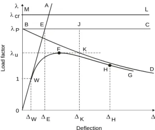
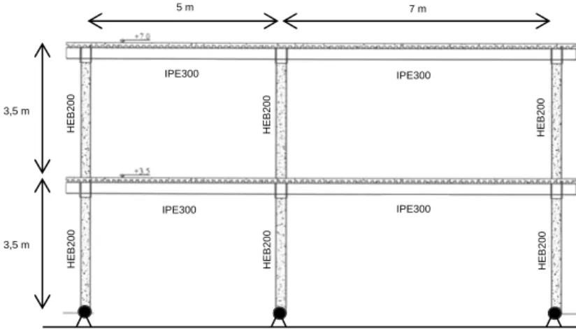
(9) Overview of the considered frame analyses In Fig. 4, the results of the different analyses described in this paragraph are qualitatively illustrated. This figure shows how the sway displacement Δ influences the value of the load factor λ got from the several types of analysis. The line “OA” corresponds to a purely elastic first-order analysis. The result of an elastic critical analysis is given by the horizontal line “ML”, the ordinate of which corresponds to the elastic critical load factor λcr. The first-order rigid-plastic analysis is represented by the curve “OBC”; when the first-order rigid-plastic load factor λp is reached (in “B”), the failure develops under constant load (“BC” line). The behavior got from the second-order rigidplastic analysis is represented by the “OBD” curve: when the rigid-plastic load factor λp is reached (in “B”), its value decreases with an increasing transverse displacement (“BD” curve). The “OFG” curve results from a non-linear analysis; it is likely to reflect the “actual” frame behavior. The ultimate load factor λu corresponds to the peak ordinate of the loaddisplacement curve (in “F”). If, at λu, the failure of the structure is due to the formation of a full plastic mechanism, the “actual” behavioral curve “OFG” obtained through the non-linear analysis and the line “OBD” relative to the second-order rigid-plastic analysis join at point “F”, in this particular case, point “F” should correspond to point “K” in Fig. 4. If a global frame instability occurs before the development of a plastic mechanism, the “actual” curve remains below the second-order rigid-plastic one “OBD” and point “F” differs from point “K”. This situation is illustrated in Fig. 4.. “Ispra” building Only the “Ispra” building designed for static loading is examined herein (see description given here above). It is 12 m long and is composed of two-storey two-bay frames that are 12 m large, 7 m high and 3 m spaced. These frames resist in-plane loading by frame action without exhibiting out-of-plane deformation because they are braced in the perpendicular direction.. 9.
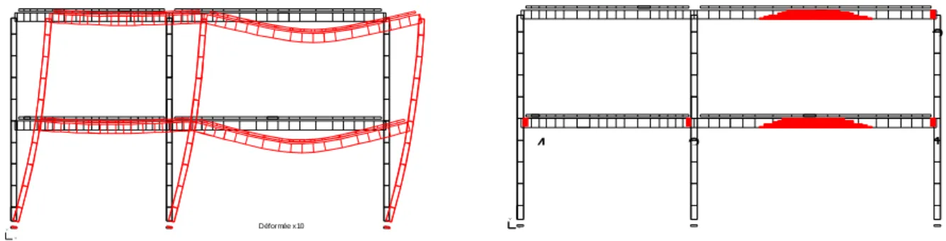
(10) The steel HEB200 columns are partially encased; the steel beams, made of IPE300 structural shapes, support reinforced concrete slabs. All the moment resistant joints develop a composite action and are classified as semi-rigid and partial-strength. The column bases are ideally pinned. One of the constitutive frames is represented here below (see Fig. 5). In addition to the self-weight of the structure, the permanent load of 1,5 kN/m2 and an imposed service load of 5 kN/m² are uniformly applied on both floors. A critical elastic analysis provides λcr = 6,494 and the ratio λSd/λcr = 0,154, with the consequence that the frame would be sway if the criterion of Eurocode 3 is generalized to composite structures. According to the first-order rigid-plastic analysis, failure corresponds to the formation of a local beam mechanism in the 7m lower right beam; it is achieved for a load factor λp = 1,843. The load-sway displacement curve obtained from a non-linear analysis is shown in Fig. 6. The ultimate load factor is λu = 1,786 while the first plastic hinge is formed at λe = 1,605. The ultimate load factor λu is not much different from the plastic load factor λp. However the respective predicted failure modes are different (Fig. 7). As the number of plastic hinges is not sufficient to develop a full plastic mechanism, failure is due to global instability and results from the progressive decrease in the sway stiffness of the frame when the plastic hinges successively develop.. “Bochum” building The “Bochum” building (Fig. 8) is a two-bay two-storey frame. The total height is 5 m and the total width is 9,8 m. Columns A and C are made of HEB260 profiles and column B of a HEB280 one. The IPE300 beams have their upper flange connected to the composite slab by means of shear studs. According to the draft European standard prEN1994-1-1, still available for confidential use only, all the joints are classified as semi-rigid and partial-strength.. 10.
(11) Due to restrictions on the experimental facilities at Bochum University, the applied actions are: - A load of 400 kN applied at the top of each column; it is supposed to represent the gravity loads transmitted by the upper storeys; - Uniform and concentrated gravity loads as indicated in Fig. 9; - Horizontal loads of 50 kN each applied at each floor level. For testing, the loading sequence was the following: all the gravity loads are first increased up to their nominal values; they are then kept constant while the horizontal loads are progressively magnified by a load factor λ till failure (see Fig. 10). This loading sequence is also the one used for the numerical analysis. The elastic critical analysis gives the load factor λcr = 9,83, so that λsd/λcr = 0,102. The latter value is just slightly larger than 0,1 with the result that it corresponds to the sway/nonsway boundary according to the Eurocode 3 criterion. A first-order rigid-plastic analysis has also been performed. When conducting hand calculations, only the following basic independent plastic mechanisms must be considered prior to their possible further combination: -. Global panel mechanism;. -. First storey panel mechanism. Plastic beam mechanisms are disregarded because the vertical loads, once applied,. are kept constant (Fig. 10). The corresponding λp values are listed in Table 1. Clearly, in accordance with the first-order rigid-plastic analysis, the failure of the structure is due to the formation of a global panel mechanism. That is in accordance with a similar FINELG computation. A non-linear analysis provides an ultimate load factor λu = 1,41 to which corresponds a top sway displacement of 85 mm (Fig. 11). A difference of 3% on λu is found with the test result. The response curve starts at an abscissa, which represents the initial out-of-plumb of. 11.
(12) the frame. The general shape of this curve, especially the descending branch in the post-limit regime, means that failure results from a global frame instability. Fig. 12 shows that the number of plastic hinges at failure is smaller than the one required to form a full plastic mechanism. As yet said previously, panel mechanisms are significantly influenced by second-order effects. A second-order rigid-plastic analysis is conducted in order to evaluate the influence of the geometrical non-linearities on the value of the first-order rigid-plastic load factor λp. The relevant results are given in Fig. 13. The descending branch of the frame response obtained from a non-linear analysis is found close to the one deduced from the second-order rigid-plastic analysis even if, as shown in Fig. 12, the corresponding failure load is not, strictly speaking, associated to a full plastic mechanism, which would need the formation of eight plastic hinges. That is due to the fact that: i) only one plastic hinge at one beam end (right handside of the left upper beam) is missing before a global panel mechanism is formed, and ii) the bending moment in this cross-section when the last hinge (the seventh) forms is only 10% lower than the plastic moment resistance of the cross section (Fig. 13). Finally, an elastic critical analysis is performed on the frame in which seven perfect plastic hinges are introduced at the beam ends and located as shown in Fig. 12. It gives an elastic critical load resultant, which amounts 95 percent of the total applied vertical loads (see Fig. 10). This last analysis confirms the above prediction that failure is due to a global frame instability, at a load level at which a partial plastic mechanism only is formed. This failure mode is also the one which has actually been observed during the test carried out in Bochum.. “Eisenach” building The “Eisenach” building is 240 m long; its width and height are respectively 54 m and 30,6 m. The three-storey three-span frames are 12 m spaced. They are subjected to wind forces in their plane and are braced in the perpendicular direction (Fig. 14).. 12.
(13) All the columns are composite. Beams at +20 m and +30,6 m levels are composed of steel trusses. At the +30,6 m level, the roof is subjected to rather small loads; therefore it is removed for the present study. For the research purposes, composite partially encased beams connected to the slabs are substituted for the beam trusses at level +20 m. The first storey, from the +8,9 m ground level, is transversally stiff and does therefore not affect the general structural behavior of the frame; for sake of simplicity, it has not been modeled. The column bases as well as the beam-to-column joints connecting the beams to the outer columns are pinned while the inner beam-to-column joints are assumed rigid. Fig. 14 shows the substitute frame with its idealized static system and corresponding loading pattern. Notation “g” is used for the permanent loads (including self-weight of the structure) and “q” for the variable loads. The elastic critical load factor λcr is 4,35 and the ratio λSd/λcr amounts 0,23; consequently, a significant influence of the second-order effects on the structural response should be expected. The first-order rigid-plastic load is reached by the formation of a local beam mechanism – in the lateral span of the first level – at a load factor λp = 1,545. The curve representing the frame behavior, which results from a non-linear analysis, is presented in Fig. 15. After the maximum load is reached, the curve goes down rapidly; that may be explained by the fact that all the plastic hinges form at the same time, so that λe = λu = 1.136 (Fig. 16). These plastic hinges enable a panel mechanism to form in the first storey – a phenomenon which is usually designated as “soft floor” – while the rest of the structure remains nearly undeformed. To get confirmation of the failure mode, two second-order rigid-plastic analyses were performed on a structure in which the first-order rigid-plastic failure mode is assumed to be either a beam mechanism – what is the case in reality – or a panel mechanism. The corresponding response curves as well as the one obtained from the non-linear analysis are shown in Fig. 17. The comparison is quite conclusive:. 13.
(14) -. Second-order sway effects do not affect the development of a beam mechanism but influence significantly the formation of a panel mechanism;. -. Failure is reached when a panel mechanism develops: the ultimate load is much lower than the one obtained based on a first-order rigid-plastic analysis. Consequently the ultimate load factor is reached where non-linear response and second-order rigidplastic “panel” response join each other.. “Luxembourg” building The building is 85,7 m long, 54 m wide and 30,6 m high. One of its constitutive frames is shown in Fig. 18. Both the beams and columns are composite. A concrete core stabilizes laterally the structure and makes the constitutive frames non-sway; however, for the research purposes, a simplified substitute frame free of central core is adopted (Fig. 18). The elastic critical load factor λcr is 5,15 and λSd/λcr = 0,194; the frame seems therefore prone to significant sway. According to the first-order rigid-plastic analysis, failure occurs when a local plastic beam mechanism is formed at a load factor λp = 1,584. The behavior of the frame predicted by a non-linear analysis is shown in Fig. 19. The ultimate load factor λu is equal to 1,21 and the one corresponding to the formation of the first plastic hinge amounts 0,99. The displacement at failure is 0,19 m, including the initial out-of-plumb. The structure fails when a panel mechanism forms in the first storey, even if the first-order rigid-plastic mechanism is a beam one. Second-order rigid-plastic analyses are performed (Fig. 20) so as to understand how the structure behaves at failure. Fig. 20 results in similar conclusions to those drawn previously for the “Eisenach” building.. Conclusions From the study of the four above composite frames, it may be concluded that the general behavioral response of such structures to static vertical and horizontal loads is quite. 14.
(15) similar to the one exhibited by steel sway frames. As a main conclusion, the application, to composite sway building frames, of practical design methods available for steel buildings may be a priori contemplated. Preliminary research works aimed at validating these statements have been initiated and the first conclusions are given in the next section.. Applicability of simplified analytical methods Introduction Several simplified analytical methods exist and some of them are proposed in Eurocode 3 (Eurocode 3 1992). The objective here is to investigate whether and how these design procedures can be generalized to composite sway frames. Two of these methods are focused on in the following paragraphs: the amplified sway moment method and the Merchant-Rankine approach. The structures used as references are those studied in the previous section. As one of the two design procedures is based on the concept of “proportional loading”, the “Bochum structure” is not further used.. Amplified sway moment method In this method, a first-order linear elastic analysis is first carried out; then, the resulting internal forces are amplified by a “sway factor” so as to ascertain for second-order sway effects. Finally, the design load resistance of the frame is derived by computing the load at which a first plastic hinge develops in the frame. This method permits a direct comparison with the elastic load factor λe evaluated numerically. The steps to be crossed when applying this elastic design procedure are as follows: -. A first-order elastic analysis is performed on the frame fitted with horizontal supports at the floor levels; it results especially in bending moment distribution and reactions at the horizontal supports;. 15.
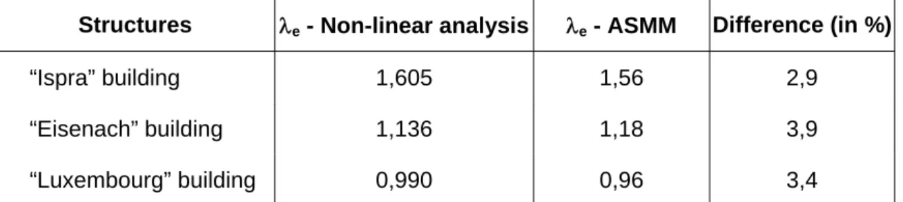
(16) -. Then, a second first-order elastic analysis is conducted on the initial frame subjected to the sole horizontal reactions obtained in the first step; the resulting bending moments are the so-called “sway moments”.. -. Approximate values of the “actual” moments result from the summing up of the moments obtained respectively in the two frame analyses, after having amplified the sole sway moments by means of the sway factor:. 1 V 1- sd Vcr. (1). where:. -. -. Vsd is the resultant of all the gravity design loads;. -. Vcr is the lowest elastic critical load associated to a global sway instability.. The maximum elastic resistance of the frame is reached as soon as the first plastic hinge forms. Above design procedure is rather simple as it only requires first-order elastic. analyses. Also the principle of superposition remains applicable, what is especially useful when having to combine loading cases. According to Eurocode 3 (Eurocode 3 1992), the amplified sway moment method is restricted to structures characterized by Vsd/Vcr ranging from 0,1 to 0,25; this condition is met in all the structures examined within the present paper. Table 2 shows how the results obtained through a full non-linear analysis (load factor λe corresponding to the formation of a first plastic hinge) compare with those got from the “Amplified Sway Moment Method” (ASMM). It may be concluded to a pretty good agreement between the two sets of results; indeed the maximum difference amounts only 3,9 %.. Merchant-Rankine approach (Maquoi & Jaspart 2001) The Merchant-Rankine method is a second-order elasto-plastic approach, which was developed for bare steel frames; it allows to assess the failure load factor through a formula. 16.
(17) that takes account of interactions between plasticity (λp) and instability (λcr) in a simplified and empirical way. A direct comparison with the ultimate load factor λu got through the numerical investigations may be achieved. The Merchant-Rankine basic formula (MR) writes:. 1 1 1 = + λ u λ cr λ p. (2.a). or:. λ*u =. λp 1+(λ p /λ cr ). >λ / p. (2.b). Should the frame be very stiff against sway displacements, then λcr is much larger than λp with the result of a low λp/λcr ratio: a minor influence of the geometric second-order effects is expectable and the ultimate load is therefore close to the first-order rigid-plastic load. In contrast, a flexible sway frame is characterised by a large value of the λp/λcr ratio. It shall collapse according to a nearly elastic buckling mode at a loading magnitude, which approaches the elastic bifurcation load. Strain hardening tends to raise plastic hinge moment resistances above the values calculated from the yield strength. Therefore most practical frames with only a few storeys in height attain a failure load at least equal to the theoretical rigid-plastic resistance. When the ratio λcr/λp is commonly greater than 10, the effects of material strain hardening more than compensate those of changes in geometry. Sometimes, additional stiffness due to cladding is sufficient to compensate such changes. To allow, in a general treatment for the minimum beneficial effects to be expected from both strain hardening and cladding, Wood suggested a slightly modified Merchant-Rankine formula (MMR):. λ*u =. λp 0.9+(λ p /λ cr ). >λ / p. (3). in the range λcr/λp ≥ 4. He recommended not to use it in practice when λcr/λp < 4 but to carry a second-order elastic-plastic analysis in this range.. 17.
(18) When λp/λcr ≤ 0.1, λu is limited to λp, what means that the frame can be designed according to the simple first-order plastic hinge theory. A clear and direct relationship may be established between this criterion and the one presented previously, which enables, according to Eurocode 3, to classify steel frames as sway (VSd / Vcr > 0,1) or rigid (VSd / Vcr ≤ 0,1). Similarly, it is seen that the limitation of the “Amplified Sway Moment Method” (ASMM) to structures with a ratio Vsd/Vcr ranging from 0,1 to 0,25 corresponds simply to the recommended field of application of the modified Merchant-Rankine formula (10 ≥ λcr/λp ≥ 4). The use of Equation (3) is commonly restricted to frames in buildings, in which: 1) The frame is braced perpendicular to its own plane; 2) The average bay width in the plane of the frame is not less then the greatest storey height; 3) The frame does not exceed 10 storeys in height; 4) The sway at each storey, due to non factored wind loading, does not exceed 1/300 of the storey height; 5) λcr/λp ≥ 4. From complementary studies carried out at Liège University (Maquoi & Jaspart 2001), the MMR approach is seen to exhibit a different degree of accuracy according to the type of failure mode resulting from a first-order rigid-plastic analysis: -. safe. for beam plastic mechanisms;. -. adequate. for combined plastic mechanisms;. -. unsafe. for panel plastic mechanisms.. As a result, the application of the MMR approach to structures exhibiting a first-order panel plastic mechanism should therefore be prohibited. In reference (Maquoi & Jaspart 2001), the scope of the MMR formula is extended to structures with semi-rigid and/or partial-strength joints and its applicability to composite steelconcrete structures is contemplated. The MMR approach cannot be applied to composite construction in a straightforward way. It has been developed for sway steel building frames where the loss of stability is related to the onset of plastic hinges. Another source of deformability exists in composite structures, concrete cracking, which develops well before the formation of the first plastic. 18.
(19) hinge. This effect, which is specific to composite construction, tends to increase the lateral deflection of the frame, amplifies consequently the second-order effects and reduces the ultimate resistance of the frames. In other words, for a same number of hinges formed at a given load level in a steel frame and in a composite frame respectively, larger sway displacements are reported in the composite one. In order to incorporate this detrimental effect into the MMR approach, it is suggested in reference (Maquoi & Jaspart 2001) to substitute the critical “uncracked” instability load factor λcr,uncracked by a “cracked” one, noted λcr,cracked. Table 3 shows how the predictions of the so amended MMR approach for composite construction (CMMR) compare with the numerically derived ultimate load factors λu. Again a rather good agreement between numerical simulations and the CMMR calculation model is obtained. The somewhat too safe character of the CMMR approach for the “Ispra” building results from the nature of the first-order rigid-plastic mechanism, which corresponds to the plastic failure of the beams.. Conclusions Through these investigations, the applicability of the “Amplified sway moment method” and “Merchant-Rankine” approaches, respectively based on elastic and plastic design philosophies, is validated. Furthermore, the straightforward extension of the Eurocode 3 criterion to distinguish between sway and rigid frames to composite buildings is found to be quite acceptable. Complementary works are however still in progress at Liège University in order to improve the Merchant-Rankine approach through a more accurate consideration of the nature of the first-order rigid-plastic mechanism.. General conclusions In the last years, the construction of taller composite buildings and larger industrial halls without wind bracing systems tends to make global instability a relevant failure mode.. 19.
(20) The present paper presents numerical investigations conducted on four composite sway frames with the objective to better understand their structural behavior till failure. As a result, the influence of plasticity on the structural response of composite sway structures and on the risk of formation of a global instability mode are pointed out. The applicability to sway composite structures of two simplified design methods developed for steel sway buildings is also discussed. The “Amplified Sway Moment Method” shows a good agreement with the numerical results and therefore it seems that it may be generalized with full confidence. Similarly the general accuracy of the slightly modified “Merchant-Rankine approach”, already highlighted in reference (Maquoi & Jaspart 2001), is shown but complementary investigations are still to be carried out in the future in order to allow it to better tackle the actual failure mode. Finally it has to be noted that some quite important aspects have been disregarded in the present study: creep and shrinkage effects in concrete, slips at the interface between the steel beam and the reinforced concrete slab, influence of theses slips on the response of the composite joints, … Further investigations are planned at Liège University and by that way it is hoped that replies will be brought to some of these still pending problems.. References Braconi A., Caramelli S. & Salvatore W. (2001). “Applicability of composite structures to sway frames – Annual report 2001.“ Report for the ECSC project 7210-PR-250, Pisa University, Italy.. Demonceau J.F. & Jaspart J.P. (2001). “Applicability of composite structures to sway frames – Technical annual report 2001.” Report for the ECSC project 7210-PR-250 “Applicability of composite structures to sway frames”, Liège University, Belgium.. 20.
(21) Demonceau J.F. &. Jaspart J.P. (2002a). “Applicability of composite structures to sway. frames. Technical annual report 2002.” Report for the ECSC project 7210-PR-250 “Applicability of composite structures to sway frames”, Liège University, Belgium.. Demonceau J.F. & Jaspart J.P. (2002b). “Design of the structure for the full scale test to be tested in Ispra – Pre-calculations at the University of Liège.” Report for the ECSC project 7210-PR-250 “Applicability of composite structures to sway frames”, Liège University, Belgium.. Demonceau J.F. & Jaspart J.P. (2003). “Validation of the FEM technique for the numerical simulation of the response of composite building frames. Common report on a Benchmark study.” Report for the ECSC project 7210-PR-250 “Applicability of composite structures to sway frames”, Liège University, Belgium.. Eurocode 3 (1992). “Design of Steel Structures. Part 1.1: General Rules and Rules for Buildings.” European Prestandard, ENV 1993-1-1, CEN, Brussels.. Eurocode 4 (1992). “Design of Composite Steel and Concrete Structures. Part 1.1: General Rules and Rules for Buildings.” European Prestandard, ENV 1994-1-1, CEN, Brussels.. FINELG User’s manual (1999). “Nonlinear finite element analysis program.” 7th up-date, Liège University and BEG Design Office, Belgium.. Hensman J. S. (1998). “Investigation of the wind-moment method for unbraced composite frames.” Ph.D. thesis, Nottingham University (U.K.).. 21.
(22) Jaspart J.P. (1991). “Study of the semi-rigidity of beam-to-column joints and its influence on the resistance and stability of steel buildings.” PhD thesis, M&S Department, Liège University, Belgium (in French).. Kraus M. (2002). “Applicability of composite structures to sway frames – Annual report 2002.” Report for the ECSC project 7210-PR-250 “Applicability of composite structures to sway frames”, Bochum University, Germany.. Li T. Q., Moore D. B., Nethercot D. A. & Choo B. S. (1996a). “The experimental behavior of a full-scale, semi-rigidly connected composite frame: overall considerations.” Journal of Constructional Steel Research, Vol. 39, pp. 167-191.. Li T. Q., Moore D. B., Nethercot D. A. & Choo B. S. (1996b). “The experimental behavior of a full-scale, semi-rigidly connected composite frame: detailed appraisal.” Journal of Constructional Steel Research, Vol. 39, pp. 193-220.. Majkut S. (2001). “Extension of Eurocode 4 to the computation of composite sway buildings.” Diploma work (2000 – 2001), M&S Department, Liège University, Belgium (in French).. Maquoi R. et Jaspart J.P. (2001). “A simple approach for the design of steel and composite frames accounting for effective overall stability.” Festschrift Prof. Richard Greiner, Graz University, Austria.. Pecquet E. (2002). “Contribution to the development of computation rules for steel-concrete sway composite buildings.” Diploma work (2001 – 2002), M&S Department, Liège University, Belgium (in French).. 22.
(23) Type of mechanism. λp. Panel mechanism (minimum obtained for global panel mechanisms). 1.82. Combined mechanism. 9.42. Table 1: Results from a first-order rigid-plastic analysis. 23.
(24) λe - Non-linear analysis. λe - ASMM. Difference (in %). “Ispra” building. 1,605. 1,56. 2,9. “Eisenach” building. 1,136. 1,18. 3,9. “Luxembourg” building. 0,990. 0,96. 3,4. Structures. Table 2: Comparison between the results of the non-linear and ASMM approaches. 24.
(25) λu - Non-linear analysis. λu – CMMR. Difference (in %). “Ispra” building. 1,790. 1,440. 19,4. “Eisenach” building. 1,138. 1,136. 0,2. “Luxembourg” building. 1,207. 1,181. 2,3. Structures. Table 3: Comparison between non-linear analyses and M-R. 25.
(26) Fig. 1: Reference structure for the benchmark study Fig. 2. Applied loading Fig. 3. Frame B: lower beam load-deflection curves Fig. 4. Graphical representation of the results obtained through the different analyses Fig. 5. Composite frame of the “Ispra” structure Fig. 6. Behavior of the “Ispra” frame Fig. 7. Structural deformed shapes and yield pattern at failure Fig. 8. General layout of the 2-D frame test Fig. 9. Loading conditions for the “Bochum” frame Fig. 10. Loading sequence Fig. 11. Top displacement – total horizontal load for the “Bochum” structure Fig. 12. Location of the plastic hinges at failure for the “Bochum” structure Fig. 13. Second-order rigid-plastic analysis for the “Bochum” structure Fig. 14. From the actual “Eisenach” structure to the substitute frame Fig. 15. Non-linear behavior of the “Eisenach” frame Fig. 16. Deformed shape and yield pattern at failure for the “Eisenach” frame Fig. 17. Second-order effects in the Eisenach frame Fig. 18. From the actual “Luxembourg” structure to the simplified substitute frame Fig. 19. Behavior of the Luxembourg frame. 26.
(27) Fig. 20. Second-order effects in the Luxembourg building. 27.
(28) 3,6 m. Frame A. 3,6 m. Frame B. 4,953 m. 4,953 m. Fig. 1: Reference structure for the benchmark study. 28.
(29) F. F. F. F. F. F. F. F. Fig. 2. Applied loading. 29.
(30) Total load on the beam [kN]. 450 400 350 300 250 200. Aachen. 150. Pisa. 100. Liège. 50. Test. 0 0. 10. 20. 30. 40. 50. 60. 70. 80. Relative mid-span deflection [mm] Fig. 3. Frame B: lower beam load-deflection curves. 30.
(31) λ M λ cr. Load factor. λP. A. B. L J. E. F. λu. C. K. D. H 1. 0. G W. ΔW ΔE. ΔK. ΔH. Δ. Deflection. Fig. 4. Graphical representation of the results obtained through the different analyses. 31.
(32) 5m. 7m. IPE300. HEB200. HEB200. HEB200. IPE300. IPE300 3,5 m. HEB200. HEB200. 3,5 m. HEB200. IPE300. Fig. 5. Composite frame of the “Ispra” structure. 32.
(33) Load factor. 2 1.8 1.6 1.4 1.2 1 0.8 0.6 0.4 0.2 0. λu= 1.786 λe = 1.605. 0. 0.02. 0.04. 0.06. 0.08. 0.1. 0.12. Transverse displacement at the top of the frame [m] Fig. 6. Behavior of the “Ispra” frame. 33.
(34) 2. 4. 3. 1. Y. Déformée x10. Y. X. X. Fig. 7. Structural deformed shapes and yield pattern at failure. 34.
(35) 2.50 m 2.49 m. 5.87 m. 3.89 m. Fig. 8. General layout of the 2-D frame test. 35.
(36) 400 kN. 400 kN 15 kN. 400 kN 15 kN. 50 kN. 3,5 kN/m. 3,5 kN/m. 50 kN. Fig. 9. Loading conditions for the “Bochum” frame. 36.
(37) Vertical loading. 1262,4 kN. λu Horizontal load factor λ Fig. 10. Loading sequence. 37.
(38) Load factor λ. λu = 1,41. 1.5 1.4 1.3 1.2 1.1 1 0.9 0.8 0.7 0.6 0.5 0.4 0.3 0.2 0.1 0 0. 0.02. 0.04. 0.06. 0.08. 0.1. 0.12. 0.14. 0.16. 0.18. 0.2. Horizontal top displacement [m]. Fig. 11. Top displacement – total horizontal load for the “Bochum” structure. 38.
(39) Fig. 12. Location of the plastic hinges at failure for the “Bochum” structure. 39.
(40) 2 1,8. λp = 1,82. Load factor. 1,6 1,4 1,2. λu = 1,41. 1 0,8. Non-linear analysis. 0,6. Second-order rigid-plastic analysis. 0,4. First-order rigid-plastic analysis. 0,2 0 0. 0,02. 0,04. 0,06. 0,08. 0,1. 0,12. 0,14. 0,16. 0,18. 0,2. Horizontal top displacement [m] Fig. 13. Second-order rigid-plastic analysis for the “Bochum” structure. 40.
(41) Fig. 14. From the actual “Eisenach” structure to the substitute frame. 41.
(42) λe = λu = 1,136. 1.2. Load factor. 1 0.8 0.6 0.4 0.2 0 0. 0.1. 0.2. 0.3. 0.4. 0.5. 0.6. 0.7. 0.8. 0.9. 1. Transverse displacement at the top of the frame [m]. Fig. 15. Non-linear behavior of the “Eisenach” frame. 42.
(43) Déformée x8. Fig. 16. Deformed shape and yield pattern at failure for the “Eisenach” frame. 43.
(44) 2 1,8 1,6. Load factor. 1,4. Second-order rigid-plastic analysis - panel mechanism Non-linear analysis Second-order rigid-plastic analysis - beam mechanism. 1,2 1 0,8 0,6 0,4 0,2 0 0. 0,1. 0,2. 0,3. 0,4. 0,5. 0,6. 0,7. 0,8. 0,9. 1. 1,1. Transverel displacement at the top of the frame [m]. Fig. 17. Second-order effects in the Eisenach frame. 44.
(45) 0m. Fig. 18. From the actual “Luxembourg” structure to the simplified substitute frame. 45.
(46) 1.4. λu = 1,21. 1.2. Load factor. 1. λe = 0.99. 0.8 0.6 0.4 0.2 0 0. 0.05. 0.1. 0.15. 0.2. 0.25. 0.3. 0.35. 0.4. 0.45. 0.5. 0.55. 0.6. Transverse displacement at the top of the frame [m] Fig. 19. Behavior of the Luxembourg frame. 46.
(47) 2.7. Second-order rigid-plastic analysis - panel mechanism Non-linear analysis Second-order rigid-plastic analysis - beam mechanism. 2.4. Load factor. 2.1 1.8 1.5 1.2 0.9 0.6 0.3 0 0. 0.05. 0.1. 0.15. 0.2. 0.25. 0.3. 0.35. 0.4. 0.45. 0.5. 0.55. 0.6. Transverse displacement at the top of the frame [m] Fig. 20. Second-order effects in the Luxembourg building. 47.
(48)
Figure


+7


Documents relatifs
The fission barriers standing in the quasi-molecular shape path have been de- termined within a generalized liquid drop model taking into account the nuclear proximity energy, the
Chapter 2 of [18] presents an introduction to the MapReduce paradigm. In particular, it includes the MapReduce algorithm for cascade joins that we en- hance with privacy
allele (allele more frequent in M. trossulus reference samples), blue dots: homozygotes for the edulis/galloprovincialis allele (allele in higher frequency in M.
In the literature, some simulators have been proposed for intraarticular needle injection. Forest et al. [5] proposed to use two identical haptic devices to achieve a simulator
Pas vijf jaar nazijn dood kon Mettes'werk het geijkte parcours van ontvangst in. Het mag niet verwonderen dat de kritiek het zwaarder kreeg dan normaal. Wat moest
Pusa benyuan jing 菩薩本緣經 (Sūtra sur les actes fondamentaux du bodhisattva) Taizi ruiying benqi jing 太子瑞應本起經 (Sūtra sur les circonstances propices à la
Etat animateur, Nouvelle Gestion Publique et GRH dans le privé: la fin de la théorie wébérienne. •
Parcours d’éducation thérapeutique des patients diabétiques de type 2 : analyse des collaborations et partage des tâches entre professionnels de santé, Médecine des Maladies
