HAL Id: hal-01774033
https://hal.archives-ouvertes.fr/hal-01774033
Submitted on 23 Apr 2018
HAL is a multi-disciplinary open access
archive for the deposit and dissemination of sci-entific research documents, whether they are pub-lished or not. The documents may come from teaching and research institutions in France or abroad, or from public or private research centers.
L’archive ouverte pluridisciplinaire HAL, est destinée au dépôt et à la diffusion de documents scientifiques de niveau recherche, publiés ou non, émanant des établissements d’enseignement et de recherche français ou étrangers, des laboratoires publics ou privés.
Tailoring the electrochemical and mechanical properties
of PEDOT : pss films for bioelectronics
Mohammed Elmahmoudy, Sahika Inal, Anne Charrier, Ilke Uguz, George
Malliaras, Sébastien Sanaur
To cite this version:
Mohammed Elmahmoudy, Sahika Inal, Anne Charrier, Ilke Uguz, George Malliaras, et al.. Tailor-ing the electrochemical and mechanical properties of PEDOT : pss films for bioelectronics. Macro-molecular Materials and Engineering, Wiley-VCH Verlag, 2017, 302 (5), �10.1002/mame.201600497�. �hal-01774033�
DOI: 10.1002/((please add manuscript number))
Article type: Full Paper
Tailoring the Electrochemical and Mechanical Properties of PEDOT: PSS
Films for Bioelectronics
Mohammed H. ElMahmoudy, Sahika Inal*, Anne Charrier, Ilke Uguz, George G. Malliaras, and Sébastien Sanaur
M. H. ElMahmoudy, Dr. S. Inal, I. Uguz, Prof. G. G. Malliaras
Department of Bioelectronics, Ecole Nationale Supérieure des Mines de Saint-Etienne, 13541 Gardanne, France
Dr. S. Inal
Biological and Environmental Science and Engineering, King Abdullah University of Science and Technology (KAUST) Thuwal, 23955-6900, Kingdom of Saudi Arabia
*Corresponding author email: sahika.inal@kaust.edu.sa Dr. A. Charrier
Aix-Marseille University, CNRS, CINAM, Marseille, France Dr. S. Sanaur
Department of Flexible Electronics, Ecole Nationale Supérieure des Mines de Saint-Etienne, 13541 Gardanne, France
Keywords: organic bioelectronics, poly(3,4-ethylenedioxythiophene): polystyrene sulfonate (PEDOT: PSS), organic electrochemical transistor, thin films, cross-linker, Young’s modulus
1. Introduction
Bioelectronics uses electrical signals to interact with biological systems. Sensors that allow for electrical read-out of important disease markers, and implants/stimulators used for the detection and treatment of pathological cellular activity are only a few examples of what this technology can offer[1–2]. In the last few decades, due to their intriguing electroactive and mechanical properties, organic electronics or -conjugated materials have been extensively explored regarding their use in bioelectronics applications[3-8]. Historically, the interest in
organic electronic materials stemmed from their soft and flexible nature which dampens the mechanical properties mismatch with tissue[7]. This less “foreign” surface enhances the signal
transfer to/from cells in vitro[9]. It also elicits a small foreign body response when used in vivo, improving the performance as well as the lifetime of the implanted device. The other
1 2 3 4 5 6 7 8 9 10 11 12 13 14 15 16 17 18 19 20 21 22 23 24 25 26 27 28 29 30 31 32 33 34 35 36 37 38 39 40 41 42 43 44 45 46 47 48 49 50 51 52 53 54 55 56 57 58 59 60 61 62
attractive feature of -conjugated materials and more particularly of conducting polymers for bioelectronics is their mixed electronic/ionic conductivity[10-12]. Mixed conductivity enables coupling between the electronic charges in the bulk of the organic films with ion fluxes in biological medium. This translates into low electrochemical impedance at the biotic interface and therefore efficient transduction as well as stimulation of biological signals. As a matter of fact, the materials research for bioelectronics strives for soft materials that exhibit low impedance.
The prototypical material of organic bioelectronics is the conducting polymer poly(3,4-ethylenedioxythiophene) (PEDOT) doped with polystyrene sulfonate (PSS). PEDOT: PSS is commercially available, water-dispersible conjugated polymer complex that can be cast into films of high hole and cation conductivity, good charge storage capacity, biocompatibility, and chemical stability. In PEDOT: PSS films, PEDOT chains accumulate in a pancake-like morphology surrounded by a PSS network[11]. While hole transport is facilitated within/among the PEDOT aggregates, the PSS phase attracts a considerable amount of water, enabling penetration and transport of ions in the film. Ion transport, and consequently electrochemical activity, benefits from such hydrated pathways. This, however, brings together the challenge of maintaining the integrity of films when exposed to an aqueous environment such as the biological tissue for in vivo applications and the cell culture media for in vitro studies.
In order to avoid delamination/disintegration of the films in aqueous environment, PEDOT: PSS dispersions are typically mixed with other chemical compounds. Some studies have reported blending the dispersion with water soluble polymers such as the polyvinyl alcohol (PVA)[13-16]. The main problem with these blends is the dramatic drop in the conductivity. For instance, when mixed with PVA at a weight ratio of 20 and 60 %, the electrical conductivity
1 2 3 4 5 6 7 8 9 10 11 12 13 14 15 16 17 18 19 20 21 22 23 24 25 26 27 28 29 30 31 32 33 34 35 36 37 38 39 40 41 42 43 44 45 46 47 48 49 50 51 52 53 54 55 56 57 58 59 60 61 62
of films dropped by 1 and 5 orders of magnitude, respectively[13]. The silane based crosslinking agent, 3-glycidoxypropyltrimethoxysilane (GOPS), on the other hand, was reported to make relatively stable PEDOT: PSS films (with conductivities up to 800 S cm-1) for a large variety of bioelectronics devices[17–24], when used at a particular concentration in
the dispersion (0.1 wt%). The epoxy group in GOPS (see the inset of Figure 1 for the chemical structure of GOPS) can react with amines, thiols, and acids, as well as interacting with itself and covalently with SiO2 substrates[25]. Although the interaction mechanism
between GOPS and PEDOT: PSS is yet unclear, XPS studies suggested that the cross-linker can polymerize in water to form a multilayered structure[26]. However, depending on its
concentration in the film, GOPS might change electronic and ionic transports as well as
mechanical properties of PEDOT: PSS, presumably due to alterations on the structure and
morphology of films. Only a few reports have touched upon the effect of GOPS concentration
on the electrical properties of the resulting films[27]. Nevertheless, it is essential to maintain the electrical performance and softness of PEDOT: PSS while improving the thin film stability in aqueous media using a stabilizer such as GOPS. This is particularly crucial for long term use of bioelectronic devices, a direct example being the organic electrochemical transistors (OECTs) which are chronically implanted into cortex to record neural activities. Balancing these needs requires a systematic synthetic work or processing related interventions which aim to improve the electrochemical properties while not impeding mechanical properties. Moreover, materials with high performance electronic properties and physical characteristics matched to those of the tissue have great potential to bring forth applications for soft electronics. Here, post-processing can provide alternative modification routes as crystalline materials exhibiting high charge mobility typically have low mechanical resilience.
In this work, we investigate the effect of GOPS content in PEDOT: PSS dispersions on the properties of films spun cast from these formulations. We find out that the concentration of
1 2 3 4 5 6 7 8 9 10 11 12 13 14 15 16 17 18 19 20 21 22 23 24 25 26 27 28 29 30 31 32 33 34 35 36 37 38 39 40 41 42 43 44 45 46 47 48 49 50 51 52 53 54 55 56 57 58 59 60 61 62
GOPS has a tremendous, yet gradual impact on the electrical, electrochemical, and mechanical properties of the PEDOT: PSS/GOPS films and that there is an optimum concentration which maximizes a particular feature of the film such as its water uptake or elasticity. The benefits of aqueous stability and mechanical strength with GOPS are to be compensated by an increase in the electrochemical impedance. Our findings suggest that a trade-off cross-linker concentration exists, which enables sufficient electrical conductivity with mechanical robustness and stability in aqueous environment.
2. Results and Discussion
2.1 Effect of the cross-linker on electrical properties
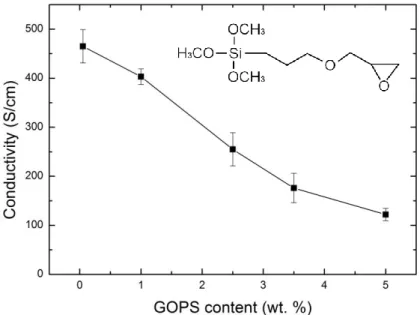
To gain insight into the effect of the cross-linker on the electrical properties of dry PEDOT: PSS films, we casted films from dispersions containing a variety of GOPS concentration (0.05, 1, 2.5, 3.5 and 5 wt%) in addition to a constant concentration of the conductivity enhancer, ethylene glycol (EG, 5 vol%) and the surfactant, dodecyl benzene sulfonic acid (DBSA, 0.002 vol%). The films were spin-cast at the same speed on four sets of substrates: Au-coated polyimide films (Au thickness: 100 µm, surface area: 96.7 mm² and 24 mm²) and glass substrates of different geometries (25 x 25 mm², 75 x 25 mm²). Figure 1 shows that GOPS content in the film affects the bulk conductivity significantly: the highest conductivity (ca. 460 S.cm-1) is observed for the film containing the least amount of GOPS (0.05 wt%),
whereas the conductivity dropped by 4 times (120 S.cm-1) with a GOPS concentration of 5 wt%. These results are in agreement with those of Zhang et al who reported a gradual decrease in the conductivity of PEDOT: PSS film (cast from a dispersion with 5 vol% glycerol and 0.5 vol% of DBSA) with an increase in GOPS concentration[27]. The Clevios PH1000 PEDOT: PSS dispersion has a polymer content of 1.15 wt%, with a PEDOT to PSS ratio of 1:2.5 (ca. 0.3 wt% PEDOT and ca. 0.8 wt% PSS). It is intriguing that although
1 2 3 4 5 6 7 8 9 10 11 12 13 14 15 16 17 18 19 20 21 22 23 24 25 26 27 28 29 30 31 32 33 34 35 36 37 38 39 40 41 42 43 44 45 46 47 48 49 50 51 52 53 54 55 56 57 58 59 60 61 62
PEDOT: PSS comprises only 18.5 wt% in the presence of 5 wt% GOPS, the conductivity of the film exceeds 100 S.cm-1.
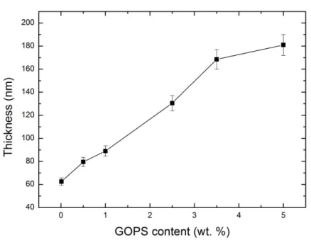
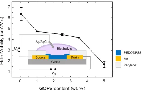
Moreover, the films processed from dispersions that contained more GOPS are thicker than the ones that had less of the cross-linker (ca. 3x difference between 0.05 wt% and 5 wt% of GOPS, Figure S1). We attribute this to an increase in the viscosity of the dispersions in the presence of GOPS. On the other hand, interactions of the cross-linker with the non-volatile additives in the dispersion might lead to an increased material content since the amount of cross-linked network in the film with respect to the PEDOT: PSS increases with GOPS content[27]. This can as well account for the observed decrease in the conductivity as a larger content of non-evaporating and non-conducting species would be present in the film[27]. However, for our case, i.e., dispersions containing EG, X-ray studies showed no evidence for EG remaining in the films[11]. We therefore attribute the decrease in electrical conductivity to a dilution effect of the conducting phase by the cross-linker. Indeed, hole mobility also decreases ca. 4 times in the range of cross-linker concentrations investigated. The mobilities were estimated by measuring OECTs prepared from PEDOT: PSS formulations of different GOPS concentrations (Figure S2 and experimental section). For instance, while the hole mobility of the 0.05 wt% GOPS-cast film is 6.4 cm2 V-1 s-1, this value drops to 1.7 cm2 V-1 s-1 for the 5 wt% GOPS-cast film. It is likely that GOPS limits the extent of aggregation of PEDOT chains by introducing crosslinks into the system. In an OECT, upon application of a positive gate voltage (VG), cations from the electrolyte are injected into the channel,
compensate the sulfonate groups of the PSS and deplete the holes of the PEDOT (See Figure S2 for a schematic of an OECT). This mechanism is measured as a decrease in the drain current (ID). The performance of an OECT is therefore evaluated as its transconductance (gm=
𝜕𝐼D
𝜕𝑉G), i.e., the extent of the modulation of the drain current with a change in gate voltage. As 1 2 3 4 5 6 7 8 9 10 11 12 13 14 15 16 17 18 19 20 21 22 23 24 25 26 27 28 29 30 31 32 33 34 35 36 37 38 39 40 41 42 43 44 45 46 47 48 49 50 51 52 53 54 55 56 57 58 59 60 61 62
the GOPS content in the channel increases, not only the channel becomes less conductive, we also measure a gradual decrease in the transconductance of OECTs (Figure 2).
2.2 Cross-linked PEDOT: PSS properties in aqueous environment
Since applications in bioelectronics necessitate an aqueous environment, it is critical to characterize the properties of the polymer film in aqueous working conditions. Using the quartz crystal microbalance dissipation (QCM-D), we quantify the swelling capability of the PEDOT: PSS/GOPS films cast on quartz crystals when exposed to DI water or an aqueous solution of NaCl. In these measurements, a decrease in the frequency (f) accompanied with an increase in dissipation (D) with the inflow of water indicates an increase in the mass of the film, i.e. swelling due to uptake of molecules. Here, the inflow of NaCl induces a further decrease in f for all samples, attributed to penetration of solvated ions in addition to the trapped water molecules. In order to quantify the swelling of the films casted from different GOPS concentrations, we treated our data both with Sauerbrey model which directly correlates the change in f to coupled mass (more appropriate for rigid films) and with Kelvin-Voigt model which is considered typically for soft films (see Experimental section). The swelling percentages estimated from these two models are summarized in Table S1. The results suggest a reduction in the swelling capacity of films with an increase in GOPS content (Figure 3a). The ability of PEDOT: PSS film to uptake water drops from 397% to 12% when GOPS concentration increases from 0.05 to 5 wt%. Using AFM to estimate the thickness of PEDOT: PSS films before and after exposure to DI water, Duc et al. reported a swelling ratio of a 40 ± 1% for a PEDOT: PSS film that contained 1 wt% of GOPS[28]. This value is well below our estimations (ca. 266%) for the same formulation. These authors also reported 660 ± 90% swelling for a PEDOT: PSS film that does not contain GOPS. Using the same technique, Stavrinidou et al. reported 155 ± 53 % of swelling for the film prepared in the absence of
1 2 3 4 5 6 7 8 9 10 11 12 13 14 15 16 17 18 19 20 21 22 23 24 25 26 27 28 29 30 31 32 33 34 35 36 37 38 39 40 41 42 43 44 45 46 47 48 49 50 51 52 53 54 55 56 57 58 59 60 61 62
GOPS and 35 ± 4 % in the presence of 1 wt% of GOPS[19]. These variations in the reported values could be due to the characterization techniques, the film/dispersion preparation, and the measurement conditions. The latter is particularly challenging to control since PEDOT: PSS films change their volume rather rapidly due to the humidity in the environment. Our results are rather meant to demonstrate the relative decrease in swelling with changing the GOPS content in PEDOT: PSS/GOPS films. For our measurements, we dried the films under vacuum over night to ensure that the film has minimal water trapped prior to its interactions with water molecules. Notably, we observed that such a dry film requires ca. two hours under constant water flow to reach a steady-state change in frequency, i.e., fully hydrated state. (Table S1). Interestingly, although the film that contained a higher GOPS content was thicker than the one that had less GOPS, its stabilization time was shorter: 30 min for 5 wt% GOPS-cast film in comparison to ca. 103 min for 1 wt% GOPS-GOPS-cast film. Taken together, the trend of stabilization time and GOPS content is consistent throughout the whole formulation series.
It is absolutely mandatory to investigate the impedance characteristics of conducting materials dedicated to bioelectronics applications. Figure 3b shows the electrochemical impedance (Z) of PEDOT:PSS/GOPS films measured at 1 kHz as a function of the cross-linker concentration. Here, since the films had different thicknesses due to variations in GOPS content (Figure S1), we normalized Z values measured at 1 kHz for a 100nm-thick film. First, the Bode plots (log
Z vs log frequency) were fit to an equivalent circuit model (RC) to extract the resistance (R)
and capacitance (C) values. Then, the capacitance was estimated for a 100 nm thick film using 𝐶′= 𝐶×100
𝑑 , where C’ is the normalized impedance and d (in nm) is the film thickness. Finally,
C’ was substituted in the impedance formula (|𝑍′| = √𝑅2+ 1
𝜔2𝐶’2 ) to estimate the normalized
impedance (𝑍′), knowing that the change in R is negligible. Our results show that 1 kHz
impedance increases indistinctly as the film contains more GOPS. This is in fact consistent
1 2 3 4 5 6 7 8 9 10 11 12 13 14 15 16 17 18 19 20 21 22 23 24 25 26 27 28 29 30 31 32 33 34 35 36 37 38 39 40 41 42 43 44 45 46 47 48 49 50 51 52 53 54 55 56 57 58 59 60 61 62
with the trend in swelling. At low GOPS concentrations, the film uptakes more water (Figure 3a), suggesting that the ions of the electrolyte can more readily penetrate and travel inside the polymer film without significant accumulation at the polymer/electrolyte interface, leading to low impedance values. Likewise, less swelling at high GOPS content impedes ionic mobility in the film, resulting in higher impedance.
Finally, we studied the effect of GOPS on the mechanical properties of PEDOT: PSS films in solution via Nano-indentation experiment using the tip of an atomic force microscope (Figure 4a). During the course of the experiment, the tip–sample distance is modulated and the subsequent interaction between the tip and the sample is monitored through the vertical displacement of the cantilever probe. Young’s modulus can be extracted from such force-distance curves using the appropriate model. In this experiment, we used a derived model of the Sneddon contact mechanics assuming a conical tip with a non-negligible radius of curvature at its apex in contact with a flat surface[29]. The applied force (F) and the indentation
(h) are related with the Young modulus (E), the Poisson ratio ( ~ 0.5), the radius of curvature
of the tip apex (R), and the half opening angle of the tip () as in the following: 𝐹 =𝜋.(1−2𝐸2){2𝑅ℎ[1 − 𝑡𝑎𝑛(𝜃)] + ℎ2𝑡𝑎𝑛(𝜃)} (1)
For each sample prepared, a series of 50 measurements was performed at different locations of the film. A typical challenge encountered for thin films is that the deformation of the film under the tip goes through continuous change by the presence of the hard substrate underlying the sample. This results in an overestimation of the Young moduli. In our case, the thickness of the films varies from 60 nm for the 0.05 wt% GOPS-cast film to 180 nm for the 5 wt% GOPS. In order to overcome challenges related to thin films, we performed the measurements at varying indentation depths. We found the Young’s modulus to drastically increase with the indentation depth, reflecting the substrate effect and that it can therefore be minimized with
1 2 3 4 5 6 7 8 9 10 11 12 13 14 15 16 17 18 19 20 21 22 23 24 25 26 27 28 29 30 31 32 33 34 35 36 37 38 39 40 41 42 43 44 45 46 47 48 49 50 51 52 53 54 55 56 57 58 59 60 61 62
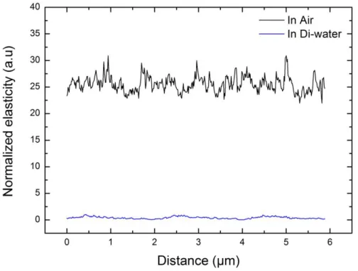
low indentation depth experiments (Figure S3). Therefore, we limited the indentations to 10 nm. The roughness of the PEDOT:PSS/GOPS films was also estimated from the AFM images taken in water (Figure S4). Samples containing 0.05 and 3.5 wt.% of GOPS exhibited an average surface roughness of 1.46 and 1.43 nm (root mean square = 1.98 and 1.81 nm) respectively. These roughness values are much smaller than the chosen indentation depth (10nm). Figure 4b shows that the Young modulus of the films increases from 90 MPa for the 0.05 wt% of GOPS to 150 MPa for the 1 wt% of GOPS. Above 2.5 wt%, the cross-linker doesn’t seem to influence the elasticity of the films (ca. 350 MPa). Moreover, we observe that the mechanical stiffness of PEDOT: PSS films decreases dramatically (by ca. 25x) in aqueous environment compared to air (Figure S5). The decrease in film stiffness in DI water is directly related to the swelling of the polymer. Our results are in agreement with those reported by Okuzaki et al (1.4 ± 0.6 GPa), and Lang et al. (1.3 ± 0.6 GPa), and by Qu et al. (2.6 ± 1.4 GPa)[30–32]. These results suggest that GOPS is a versatile additive that can be used not only to improve the aqueous stability of films but also to modify their elasticity.
As par these results, considering the use of PEDOT: PSS based OECTs for long term implantations in the brain[22], we intended to evaluate the performance of devices over several days. The OECT that was selected for this test had GOPS content that led to films with optimal water uptake, softness and conductivity: 1 wt%. Figure S6a depicts the change in the transconductance of an OECT comprising 1 wt% GOPS in the channel over 21 days, within sub-chronic period, measured in PBS. In order to obtain stable current values at day 0 (prior to the performance evaluation experiments), the devices were incubated in water overnight followed by multiple current-voltage cycles. This enabled the dissolution/diffusion of low molecular components in the film into the solution. In fact, another study reported that when gold electrodes coated with electropolymerized EDOT were soaked in a buffer for several days, the impedance of some of these electrodes raised steadily associated with decreases in
1 2 3 4 5 6 7 8 9 10 11 12 13 14 15 16 17 18 19 20 21 22 23 24 25 26 27 28 29 30 31 32 33 34 35 36 37 38 39 40 41 42 43 44 45 46 47 48 49 50 51 52 53 54 55 56 57 58 59 60 61 62
charge storage capacity. This decrease was attributed to partial delamination of the PEDOT coating in PBS [33]. Nevertheless, our devices (width = 10 µm, length = 5 µm, thickness = 275∓25 nm) showed stable transconductance values (gm= 7.3 ∓ 0.2 mS) over the course of
this study. In a separate study, we found that the devices that contain even higher (3.5 wt%) GOPS in the channel had similar performance in stability, tested over 5 days in aqueous environment (Figure S6b). Overall, the results obtained from 5 different OECTs suggest that the films cast with 1% wt of GOPS maintain their structural integrity in aqueous media and but also exhibit adequate long-term electrical performance.
3. Conclusions
In this work we investigated the electrical, swelling, electrochemical, and mechanical properties of PEDOT: PSS films modified with varying amounts of the silane based cross-linker, GOPS. As the cross-linker content increases from 0.05 to 5 wt%, we observed a drop in the bulk conductivity from ca. 530 to 120 S.cm-1, a decrease in the swelling from ca. 397% to 12%, and a relative increase in the electrochemical impedance (from ca. 15 to 20 Ohms at 1 kHz for films with thickness of 100 nm with a surface area of 96.7 mm²). The benefits of aqueous stability with GOPS are therefore to be compensated by losses in electronic transport and increase in the electrochemical impedance. Nevertheless, the presence of the cross-linker led to an increase in the mechanical strength of the films when they are hydrated (ca. 90 to 300 MPa in DI water for 0.05 and 5 wt% of GOPS in the dispersion, respectively), as these films uptake significantly less amount of water. We also emphasize the tolerance of PEDOT: PSS films to a large quantity of the cross-linker (only 18.5 wt% of PEDOT: PSS in the solution can lead to conductivity up to 100 S.cm-1). GOPS aids obtaining highly conducting films with excellent mechanical integrity in aqueous media. Moreover, devices that contain 1 wt% GOPS, which is a concentration that leads to film with high electrical conductivity with sufficient mechanical stability, exhibit steady performance over 3 weeks. These results
1 2 3 4 5 6 7 8 9 10 11 12 13 14 15 16 17 18 19 20 21 22 23 24 25 26 27 28 29 30 31 32 33 34 35 36 37 38 39 40 41 42 43 44 45 46 47 48 49 50 51 52 53 54 55 56 57 58 59 60 61 62
suggest that variations in the concentration of such a dispersion additive like GOPS can enable facile co-optimization of electrical and mechanical properties of a conducting polymer film.
4. Experimental Section
Sample Preparation: PEDOT: PSS (Clevios PH-1000 from Heraeus Holding GmbH.),
dodecyl benzene sulfonic acid (DBSA; 0.002 vol%), ethylene glycol (EG; 5 vol%) and GOPS (ranging from 0.05 to 5 wt%) were mixed, sonicated for 30 minutes at room temperature and then filtered using 1.2 µm hydrophilic syringe filters (Minisart, from Sartorius Stedim Biotech). The substrates were cleaned and exposed to plasma oxygen for 2 minutes at 100 Watts for surface activation and further cleaning. All films were spin cast at 2500 rpm for 40 sec. The films were then baked at 140°C for 1 hour. The thickness of PEDOT: PSS films was determined using a Dektak mechanical profilometer.
Electrical and Electrochemical Characterization: We measured the sheet resistance (RS in
Ω.sq-1) of PEDOT:PSS/ GOPS films cast on glass substrates using a four-point probe (Jandel
RM3-AR). Given the film thickness (d), we could calculate the resistivity (ρ = RS× d, where
ρ is resistivity in Ω.cm) from which the conductivity (1/ρ in S.cm-1) was obtained.
Electrochemical impedance spectroscopy (EIS) was performed in NaCl solution (0.1M) via an impedance spectrometer (potentiostat/galvanostat, Metrohm Autolab B.V.) with a three-electrode configuration, where the polymer-coated substrate is the working three-electrode, a Pt mesh is the counter electrode, and Ag/AgCl is used as a standard reference electrode. EIS was performed over a range of 10 kHz to 1Hz with an AC 10 mV sine wave, and a DC offset of 0 V. In order to extract capacitance (C), and the resistance, R, the spectra of films were fit to an (RC) equivalent circuit using NOVA software.
1 2 3 4 5 6 7 8 9 10 11 12 13 14 15 16 17 18 19 20 21 22 23 24 25 26 27 28 29 30 31 32 33 34 35 36 37 38 39 40 41 42 43 44 45 46 47 48 49 50 51 52 53 54 55 56 57 58 59 60 61 62
OECT fabrication and characterization: OECTs were fabricated using photolithography, as
previously described [34]. Briefly, 150 nm thick gold lines were patterned on a glass slide with S1813 photoresist, exposed to UV light using a SUSS MBJ4 contact aligner, and developed using MF-26 developer. Upon the deposition, a standard metal lift-off process in acetone was employed and gold interconnects and pads were insulated from the electrolyte by a 1.5 µm parylene C film deposited using a SCS Labcoater 2. A second sacrificial layer of parylene C was coated, patterned with AZ9260 photoresist, developed, and selectively etched by an CF6/O2 plasma using an Oxford 80 plus to define the transistor channel. Finally, PEDOT:PSS
dispersion was cast and the sacrificial layer of parylene C was peeled, and the devices were baked at 110 °C for 1 hour.
The PEDOT: PSS channel had a width/length (W/L) of 50 μm/50 μm. The transistors were operated in the common source configuration with a Ag/AgCl pellet electrode (Warner Instruments) immersed in NaCl solution (0.1M). The characterization was performed using a National Instruments PXIe-1062Q system. The gate bias was applied and controlled using a NI PXI-6289 modular instrument, and current recorded with either the NI PXI-4145 SMU or a NI PXI-4071 digital multimeter. The recorded signals were saved and analyzed using customized LabVIEW and MATLAB software. Hole mobilities were extracted using impedance matching method reported for OECTs[21].
Swelling Measurements: The swelling of the thin polymer films was investigated by quartz
crystal microbalance with dissipation set-up (QCM-D) (Q-Sense, from Biolin Scientific). PEDOT: PSS dispersions at a given GOPS concentration were spun-cast on cleaned gold-coated Q-sensors. They were then kept under vacuum overnight to ensure complete drying of
1 2 3 4 5 6 7 8 9 10 11 12 13 14 15 16 17 18 19 20 21 22 23 24 25 26 27 28 29 30 31 32 33 34 35 36 37 38 39 40 41 42 43 44 45 46 47 48 49 50 51 52 53 54 55 56 57 58 59 60 61 62
the film. Filtered DI water or aqueous NaCl solution (0.1 M) were flown over the samples at 24 ℃ at a flow rate of 50 - 100 µL.min-1 controlled by a peristaltic pump. The adsorbed mass
(∆𝑚) can be approximately estimated from ∆𝑓 using the Sauerbrey equation: ∆𝑚 = −𝐶∆𝑓𝑛
𝑛 (2)
where 𝐶 is the mass sensitivity constant (17.7 ng.cm-2 Hz at 𝑓 = 5 MHz) and ∆𝑓𝑛 is the
change in resonance frequency at 𝑛 th overtone[35]. We used the 5th overtone for our calculations. Given the initial thickness of the films, we could estimate the water uptake. Kelvin-Voigt viscoelastic model was also used (equations 3, 4, and 5) where G* is the complex shear modulus, ρ is the density (kg m-3), is the viscosity (G”/) (kg ms-1), µ is the elasticity (G’) (Pa), and δ is the thickness (m)[36].
G* = G' + jG'' = µ + j2πf (3)
Δf = f1 (n, f, ρf, µf, δf) (4)
ΔD = f2 (n, f, ρf, µf, δf) (5)
Mechanical Characterization: Young’s modulus was obtained from the force-curve
measurements that were realized by using an NTEGRA AFM system (from NT-MDT). In all experiments AFM tips (NSC35 from Mikromash) were used with typical resonant frequency of 150 kHz, spring constants ranging from 5 to 12 N.m-1 and apex radius of 8 nm as verified by scanning electronic microscopy. For each tip, the spring constant was determined using the thermal noise method after obtaining the deflection sensitivity of the cantilever by pressing the AFM tip against a hard reference silicon surface. The measurements were all performed in water after allowing the samples to hydrate for 2 hours.
Supporting Information
Supporting Information is available from the Wiley Online Library or from the author. Acknowledgements 1 2 3 4 5 6 7 8 9 10 11 12 13 14 15 16 17 18 19 20 21 22 23 24 25 26 27 28 29 30 31 32 33 34 35 36 37 38 39 40 41 42 43 44 45 46 47 48 49 50 51 52 53 54 55 56 57 58 59 60 61 62
The work was financially supported by the Agence Nationale de la Recherche (grant number: ANR-14-CE08-0006). The authors would like to also thank David C. Martin for the fruitful discussions.
Received: ((will be filled in by the editorial staff)) Revised: ((will be filled in by the editorial staff)) Published online: ((will be filled in by the editorial staff)) References
[1] Karunakaran, C., Bhargava, K. and Benjamin, R., Biosensors and bioelectronics, Elsevier, 2015, Ch 1.
[2] P. Lin, C.-W. Lin, R. Mansour, F. Gu, Biosens. Bioelectron. 2013, 47, 451. [3] G. G. Malliaras, Biochim. Biophys. Acta BBA - Gen. Subj. 2013, 1830, 4286. [4] S. Löffler, B. Libberton, A. Richter-Dahlfors, Electronics 2015, 4, 879. [5] M. Berggren, A. Richter-Dahlfors, Adv. Mater. 2007, 19, 3201.
[6] J. Rivnay, R. M. Owens, G. G. Malliaras, Chem. Mater. 2014, 26, 679.
[7] D. T. Simon, E. O. Gabrielsson, K. Tybrandt, M. Berggren, Chem. Rev. 2016, 10.1021. [8] C. Liao, M. Zhang, M. Y. Yao, T. Hua, L. Li, F. Yan, Adv. Mater. 2015, 27, 7493. [9] N. K. Guimard, N. Gomez, C. E. Schmidt, Progr. Polym. Sci. 2007, 32, 876.
[10] E. Stavrinidou, O. Winther-Jensen, B. S. Shekibi, V. Armel, J. Rivnay, E. Ismailova, S. Sanaur, G. G. Malliaras and B. Winther-Jensen, Phys. Chem. Chem. Phys., 2014,16, 2275-2279.
[11] J. Rivnay, S. Inal, B. A. Collins, M. Sessolo, E. Stavrinidou, X. Strakosas, C. Tassone, D. M. Delongchamp, G. G. Malliaras, Nat. Commun. 2016, 7, 11287.
[12] D.C. Martin and G. G. Malliaras, ChemElectroChem, 2016, 3, 686. [13] A. R. Hopkins, J. R. Reynolds, Macromolecules 2000, 33, 5221.
[14] C. Chen, A. Kine, R. D. Nelson, J. C. LaRue, Synth. Met. 2015, 206, 106.
[15] N. Liu, G. Fang, J. Wan, H. Zhou, H. Long, X. Zhao, J. Mater. Chem. 2011, 21, 18962. [16] C. Chen, J. C. LaRue, R. D. Nelson, L. Kulinsky, M. J. Madou, J. Appl. Polym. Sci. 2012, 125, 3134.
[17] D. Khodagholy, J. N. Gelinas, T. Thesen, W. Doyle, O. Devinsky, G. G. Malliaras, G. Buzsáki, Nat. Neurosci. 2015, 18, 310.
[18] D. Khodagholy, T. Doublet, M. Gurfinkel, P. Quilichini, E. Ismailova, P. Leleux, T. Herve, S. Sanaur, C. Bernard, G. G. Malliaras, Adv. Mater. 2011, 23, H268.
[19] E. Stavrinidou, P. Leleux, H. Rajaona, D. Khodagholy, J. Rivnay, M. Lindau, S. Sanaur, G. G. Malliaras, Adv. Mater. 2013, 25, 4488.
1 2 3 4 5 6 7 8 9 10 11 12 13 14 15 16 17 18 19 20 21 22 23 24 25 26 27 28 29 30 31 32 33 34 35 36 37 38 39 40 41 42 43 44 45 46 47 48 49 50 51 52 53 54 55 56 57 58 59 60 61 62
[20] J. Rivnay, P. Leleux, A. Hama, M. Ramuz, M. Huerta, G. G. Malliaras, R. M. Owens, Sci. Rep. 2015, 5, 11613.
[21] J. Rivnay, M. Ramuz, P. Leleux, A. Hama, M. Huerta, R. M. Owens, Appl. Phys. Lett. 2015, 106, 043301.
[22] D. Khodagholy, T. Doublet, P. Quilichini, M. Gurfinkel, P. Leleux, A. Ghestem, E. Ismailova, T. Hervé, S. Sanaur, C. Bernard, G. G. Malliaras, Nat. Commun. 2013, 4, 1575. [23] A. Williamson, J. Rivnay, L. Kergoat, A. Jonsson, S. Inal, I. Uguz, M. Ferro, A. Ivanov, T. A. Sjöström, D. T. Simon, M. Berggren, G. G. Malliaras, C. Bernard, Adv. Mater. 2015, 27, 3138.
[24] A. Williamson, M. Ferro, P. Leleux, E. Ismailova, A. Kaszas, T. Doublet, P. Quilichini, J. Rivnay, B. Rózsa, G. Katona, C. Bernard, G. G. Malliaras, Adv. Mater. 2015, 27, 4405.
[25] A. K. Y. Wong, U. J. Krull, Anal. Bioanal. Chem. 2005, 383, 187. [26] U. Maskos, E. M. Southern, Nucleic Acids Res. 1992, 20, 1679.
[27] S. Zhang, P. Kumar, A. S. Nouas, L. Fontaine, H. Tang, F. Cicoira, APL Mater. 2015, 3, 014911.
[28] C. Duc, A. Vlandas, G. G. Malliaras, V. Senez, Soft Matter 2016, 12, 5146-5153. [29] I. N. Sneddon, Int. J. Eng. Sci. 1965, 3, 47.
[30] H. Okuzaki, M. Ishihara, Macromol. Rapid Commun. 2003, 24, 261. [31] U. Lang, N. Naujoks, J. Dual, Synth. Met. 2009, 159, 473.
[32] J. Qu, L. Ouyang, C. Kuo, D. C. Martin, Acta Biomater. 2016, 31, 114.
[33] T. D. Y Kozai, K. Catt, Z. Du, K. Na, O. Srivannavit, R. M. Haque, J. Seymour, K. D Wise, E. Yoon, X. T. Cui, IEEE Trans Biomed Eng., 2016, 63, 111.
[34] S. Inal, J. Rivnay, P. Leleux, M. Ferro, M. Ramuz, J. C. Brendel, M. M. Schmidt, M. Thelakkat, G. G. Malliaras, Adv. Mater. 2014, 26, 7450.
[35] R. Schumacher, G. Borges, K. K. Kanazawa, Surf. Sci. 1985, 163, L621. [36] M.V. Voinova, M. Rodahl, M. Jonson, B. Kasemo, Phys. Scr. 1991, 59, 391.
1 2 3 4 5 6 7 8 9 10 11 12 13 14 15 16 17 18 19 20 21 22 23 24 25 26 27 28 29 30 31 32 33 34 35 36 37 38 39 40 41 42 43 44 45 46 47 48 49 50 51 52 53 54 55 56 57 58 59 60 61 62
Figure 1. Electrical conductivity of PEDOT: PSS films cast from dispersions with GOPS concentration of 0.05, 1, 2.5, 3.5, and 5 wt%. Error bars result from error propagation taking into account 9 measurements, and the standard deviation in film thickness determination. The chemical structure of GOPS is given in the inset to the figure.
1 2 3 4 5 6 7 8 9 10 11 12 13 14 15 16 17 18 19 20 21 22 23 24 25 26 27 28 29 30 31 32 33 34 35 36 37 38 39 40 41 42 43 44 45 46 47 48 49 50 51 52 53 54 55 56 57 58 59 60 61 62
Figure 2. The transconductance (gm= 𝜕𝐼D
𝜕𝑉G) of OECTs comprising PEDOT:PSS channels of
varying GOPS concentration. The transconductance (at VG = 0 V) was normalized with
respect to film thickness in the channel. The error bars are deduced from measurements of two identical channels (50*50 µm in length*width).
a)
b)
Figure 3. a) The relative effect of GOPS concentration in the PEDOT: PSS dispersion on the swelling capacity of the spin cast films: swelling in DI water (triangle) and aqueous NaCl solution (circles). Error bars are due to different models used to estimate the water/electrolyte
1 2 3 4 5 6 7 8 9 10 11 12 13 14 15 16 17 18 19 20 21 22 23 24 25 26 27 28 29 30 31 32 33 34 35 36 37 38 39 40 41 42 43 44 45 46 47 48 49 50 51 52 53 54 55 56 57 58 59 60 61 62
uptake and the standard deviation in film thickness determination. b) The effect of GOPS concentration in the PEDOT: PSS dispersion on the electrochemical impedance measured at 1 kHz of PEDOT: PSS/GOPS films (100 nm). Error bars result from error propagation taking into account 2 measurements.
1 2 3 4 5 6 7 8 9 10 11 12 13 14 15 16 17 18 19 20 21 22 23 24 25 26 27 28 29 30 31 32 33 34 35 36 37 38 39 40 41 42 43 44 45 46 47 48 49 50 51 52 53 54 55 56 57 58 59 60 61 62
Figure 4. a) Schematic of the AFM tip indenting PEDOT: PSS thin film b) The change in Young's modulus of PEDOT: PSS films determined in DI water as a function of GOPS content in the film.
1 2 3 4 5 6 7 8 9 10 11 12 13 14 15 16 17 18 19 20 21 22 23 24 25 26 27 28 29 30 31 32 33 34 35 36 37 38 39 40 41 42 43 44 45 46 47 48 49 50 51 52 53 54 55 56 57 58 59 60 61 62
Copyright WILEY-VCH Verlag GmbH & Co. KGaA, 69469 Weinheim, Germany, 2013.
Supporting Information
Tailoring the Electrochemical and Mechanical Properties of PEDOT:PSS films for Bioelectronics
Mohammed H. ElMahmoudy, Sahika Inal*, Anne Charrier, Ilke Uguz, George G. Malliaras and Sébastien Sanaur
Figure S1. Thickness of PEDOT: PSS films at a given spin-coating conditions (2500 rpm, 40 s) as a function of GOPS concentration in the dispersion. The error bars stand for standard deviation estimated from 3 measurements.
1 2 3 4 5 6 7 8 9 10 11 12 13 14 15 16 17 18 19 20 21 22 23 24 25 26 27 28 29 30 31 32 33 34 35 36 37 38 39 40 41 42 43 44 45 46 47 48 49 50 51 52 53 54 55 56 57 58 59 60 61 62
Figure S2. Hole mobility of PEDOT: PSS films, extracted from working OECTs, as a function of GOPS concentration in the PEDOT:PSS dispersion. The channel dimensions were 50*50 µm. Also shown is a schematic of the OECT. Cations of the electrolyte enter the channel between two gold source and drain electrodes upon application of a positive gate voltage (VG) through Ag/AgCl. This leads to a change in drain current measured at a specific
drain voltage (VD).
Table S1. Swelling ratios of PEDOT: PSS films in DI water and in NaCl solution (0.1 M) with varying GOPS content (using Sauerbrey and Kelvin-Voigt models). Standard deviation is calculated according to the swelling capacity estimated via different models.
GOPS (wt %) Swelling using Sauerbrey model (%) Swelling using Voigt model (%) Standard deviation Time to stabilize (min)
DI NaCl DI NaCl DI NaCl
0.05 283 397 364 480 58 57 66 1.0 266 386 387 497 78 86 103 2.5 113 136 224 248 79 78 61 3.5 10 17 128 130 80 83 38 5.0 2 12 127 138 89 88 31 1 2 3 4 5 6 7 8 9 10 11 12 13 14 15 16 17 18 19 20 21 22 23 24 25 26 27 28 29 30 31 32 33 34 35 36 37 38 39 40 41 42 43 44 45 46 47 48 49 50 51 52 53 54 55 56 57 58 59 60 61 62
Figure S3. Young’s modulus diverging with the indentation depth of a PEDOT: PSS film with 3.5 wt% of GOPS in the formulation. The values stabilize at indentation depth < 20 nm, which is consistent for the samples cast from dispersions with different GOPS concentrations. Red line represents an exponential fit.
a) b)
Figure S4. AFM topographical images of PEDOT: PSS/GOPS thin films comprising a) 0.05 wt. % GOPS b) 3.5 wt. % GOPS. 1 2 3 4 5 6 7 8 9 10 11 12 13 14 15 16 17 18 19 20 21 22 23 24 25 26 27 28 29 30 31 32 33 34 35 36 37 38 39 40 41 42 43 44 45 46 47 48 49 50 51 52 53 54 55 56 57 58 59 60 61 62
Figure S5. Mechanical elasticity of PEDOT:PSS (5 wt% GOPS) in air (black) and in DI water (blue) using AFM peak force tapping mode using Derjaguin– Muller–Toporov (DMT) model. a) 0 5 10 15 20 25 5,5 6,0 6,5 7,0 7,5 8,0 8,5 9,0 g m ( m S ) Time (days) 1 2 3 4 5 6 7 8 9 10 11 12 13 14 15 16 17 18 19 20 21 22 23 24 25 26 27 28 29 30 31 32 33 34 35 36 37 38 39 40 41 42 43 44 45 46 47 48 49 50 51 52 53 54 55 56 57 58 59 60 61 62
b)
Figure S6. a) The performance of an OECT (channel: PEDOT: PSS with 1 wt% GOPS) chronically submerged in sterile PBS over 21 days. The transconductance (gm) was measured
at VG = 0V. The error bars are deduced from the measurements performed with 5 different
OECTs. At day 0, each device has been cycled several times until the current values were stable, i.e., multiple current-voltage measurements were performed. Once the measurement was complete, the devices were kept in 4 °C to prevent the effects of water evaporation in the buffer on the device performance. The devices had a width of 10 µm, length of 5 µm, and a thickness of 275±25 nm. b) The gm of OECTs with channels cast from either a low (0.05
wt.%, squares) or a high (3.5 wt.%, circles) GOPS content PEDOT:PSS formulation, measured over 5 days in NaCl solution (0.1 M). The devices had a width and length of 50 µm. The transconductance was measured at VG = 0V and normalized with the thickness of the film
in the channel. These devices were cycled multiple times over 10 months.
1 2 3 4 5 6 7 8 9 10 11 12 13 14 15 16 17 18 19 20 21 22 23 24 25 26 27 28 29 30 31 32 33 34 35 36 37 38 39 40 41 42 43 44 45 46 47 48 49 50 51 52 53 54 55 56 57 58 59 60 61 62
Click here to access/download
Production Data
Figure 1.tif
Click here to access/download
Production Data
Figure 2.tif
Click here to access/download
Production Data
Figure 3a.tif
Click here to access/download
Production Data
Figure 3b.tif
Click here to access/download
Production Data
Figure 4a.tif
Click here to access/download
Production Data
Figure 4b.tif
Click here to access/download
Production Data
Figure S1.tif
Click here to access/download
Production Data
Figure S2.tif
Click here to access/download
Production Data
Figure S3.tif
Click here to access/download
Production Data
Figure S4 a.tif
Click here to access/download
Production Data
Figure S4 b.tif
Click here to access/download
Production Data
Figure S5.tif
Click here to access/download
Production Data
Figure S6 a.tif