O
pen
A
rchive
T
OULOUSE
A
rchive
O
uverte (
OATAO
)
OATAO is an open access repository that collects the work of Toulouse researchers and
makes it freely available over the web where possible.
This is an author-deposited version published in :
http://oatao.univ-toulouse.fr/
Eprints ID : 15979
To link to this article : DOI : 10.1016/j.rser.2013.12.014
URL :
http://dx.doi.org/10.1016/j.rser.2013.12.014
To cite this version :
Pardo, Pierre and Deydier, Alexandre and
Anxionnaz-Minvielle, Zoé and Rougé, Sylvie and Cabassud,
Michel and Cognet, Patrick A review on high temperature
thermochemical heat energy storage. (2014) Renewable and
Sustainable Energy Reviews, vol. 32. pp. 591-610. ISSN 1364-0321
Any correspondence concerning this service should be sent to the repository
administrator:
staff-oatao@listes-diff.inp-toulouse.fr
A review on high temperature thermochemical heat energy storage
P. Pardo
a, A. Deydier
a, Z. Anxionnaz-Minvielle
a,n, S. Rougé
a, M. Cabassud
b,c, P. Cognet
b,caCEA, LITEN, LETH, 17 rue des Martyrs, 38054 Grenoble, France
bUniversité de Toulouse; INPT, UPS, Laboratoire de Génie Chimique, 4, Allée Emile Monso, F-31432 Toulouse, France cCNRS, Laboratoire de Génie Chimique, F-31432 Toulouse, France
Keywords:
Thermal Energy Storage (TES) Thermochemical
Reversible reactions Concentrated solar plant (CSP)
a b s t r a c t
Solar thermal energy represents an increasingly attractive renewable source. However, to provide continuous availability of this energy, it must be stored. This paper presents the state of the art on high temperature (573– 1273 K) solar thermal energy storage based on chemical reactions, which seems to be the most advantageous one for long-term storage. The paper summarizes the numerical, experimental and technological studies done so far. Each system is described and the advantages and drawbacks of each reaction couple are considered.
Contents
1. Introduction . . . 591
2. Thermal energy storage: definitions . . . 592
2.1. Energy density . . . 593
2.2. Comparison of different TES systems . . . 594
3. State-of-the-art on solar thermal energy storage based on chemical reactions . . . 594
3.1. Technical disciplines and skills for developing a thermochemical TES system. . . 594
3.2. Hydrogen systems: metallic hydrides . . . 594
3.3. Carbonate systems . . . 595
3.3.1. Calcite calcination/carbonation . . . 595
3.3.2. Cerrusite calcination/carbonation . . . 597
3.4. Hydroxide systems . . . 597
3.4.1. Hydration/dehydration of magnesium oxide . . . 597
3.4.2. Hydration/dehydration of calcium oxide . . . 599
3.5. The REDOX system . . . 600
3.5.1. Oxidation/decomposition of barium peroxide . . . 600
3.5.2. Other oxidation/decomposition peroxide couples . . . 601
3.6. Ammonia system . . . 602
3.6.1. The ammonium hydrogen sulfate system. . . 603
3.6.2. Dissociation/synthesis of NH3. . . 603
3.7. Organic systems. . . 604
3.7.1. Methane reforming . . . 604
3.7.2. Cyclohexane dehydrogenation – benzene hydrogenation . . . 605
3.7.3. Thermal dissociation of sulfur trioxide . . . 608
3.8. Summary of case studies. . . 608
4. Conclusion . . . 608
References . . . 608
http://dx.doi.org/10.1016/j.rser.2013.12.014
n
Corresponding author.
1. Introduction
The use of renewable energy is essential today to decrease the consumption of fossil resources and to decrease the pro-duction of carbon dioxide partly responsible for the greenhouse effect [1]. Solar energy constitutes an attractive source of energy because it is both free and endless. It can be converted into electricity by means of a concentrated solar plant (CSP) composed of four elements: a concentrator, a receiver, a trans-port media system and a power conversion machine. However, the major drawback of this energy is its intermittence. One solution is to develop thermal energy storage (TES) systems, which will store heat during the sunshine periods and release it during the periods of weak or no solar irradiation. A CSP equipped with a TES system would continuously supply elec-tricity. Thus, the development of an efficient and cost-effective TES system is crucial for the future of this technology.
At the moment, three kinds of TES systems are known: the sensible heat storage, the latent heat storage and the thermo-chemical heat storage[1,2]. Sensible heat storage systems are the most mature technologies. They have been and are still being used in industrial plants, most notably in Spain, with the PS10 and PS20 projects (2007 and 2009) or the Andasol 1 and 2 plants (2008), but also in the USA, e.g. with Solar One (1982)[2]. Among the other techniques, thermochemical heat storage seems to be a valid option to be used as a TES system[3,4]. However, in order to be efficient and cost-effective, the appropriate reversible chemical reactions have to be identified[5]. Recently, two reviews focusing on low temperature (273–573 K) TES systems based on chemical reactions have been published. They respectively concern long-term sorption solar energy storage[6]and chemical heat pump technologies and their applications [7]. Cot-Gores et al.[8] also published a state-of-the-art on sorption and chemical reaction processes for TES application and some of the high temperature reactions are listed in the Felderhoff et al. article[9].
The purpose of this work is to provide a state-of-the-art of the thermochemical heat storage solutions, focusing on tem-peratures comprised between 573 K and 1273 K. General defini-tions as well as the disciplines involved in the development of a TES system are detailed. The experimental facilities at pilot or laboratory scales and their applications are reviewed and described. The systems have been classified according to their reaction family (carbonation, hydration, oxidation…) since they often share the same advantages and drawbacks. The main data have been compiled in 2 graphs (densities versus temperature) and a general table which summarizes the literature data about reversible reactions studied for thermochemical storage appli-cations is given.
2. Thermal energy storage: definitions
Thermal storage systems have to be used to correct the existing mismatch between the discontinuous solar energy supply and the continuous electricity consumption[1]. They involve at least three steps: heat charging, storage and discharging. Three mechanisms of storing thermal energy exist. They are described below.
In sensible heat storage systems, during the charging step, solar energy is used to heat a fluid or a solid medium, thus, increasing its energy content. Then, the medium is stored at the charging step temperature. When this energy is released (discharging step), the medium temperature decreases. The sensible heat stored is associated with this increase or decrease of temperature. The thermal energy stored by sensible heat can be expressed as
Q ¼ mCpΔT
Where m is the mass of the material (kg), Cp is the specific heat over the temperature range operation (kJ kg" 1K" 1) and ΔT is the
temperature difference (K). Two reviews list the materials and the works done for high temperature thermal energy storage based on sensible heat[1,2].
In latent heat storage, during the charging step, solar energy can be used as the heat source that initiates a phase change. Then, the medium is stored at the charging step temperature into its new phase. When this energy is released (discharging step), the medium phase changes into the first state. The latent heat stored is associated with this phase change. The thermal energy stored in phase change material can be expressed as:
Q ¼ mL
Where m is the mass of the material (kg) and L is the latent heat of the material (kJ kg" 1).Many publications deal with latent TES
systems. For instance, a review lists the materials, the heat transfer analysis and the applications [10]; another one lists both the materials and the works done for high temperature thermal energy storage based on phase change material (PCM)[11].
The reactions involved in the thermochemical heat storage system are reversible ones:
A þΔHr3 B þ C
Heat is stored during the endothermic reaction step and released during the exothermic one. The thermochemical heat stored is linked to the reaction enthalpy. During the charging step, thermal energy is used to dissociate a chemical reactant (A), into products (B) and (C). This reaction is endothermic. During the releasing step, the products of the endothermic reaction (B and C) are mixed together and react to form the initial reactant (A). This reaction is exothermic and releases heat. The products of both Nomenclature
A product A [dimensionless] B Product B [dimensionless] C product C [dimensionless]
Cp specific heat of the media, kWh kg" 1K" 1
or kJ kg" 1
K" 1
Dm gravimetric energy density, kWh kg" 1
Dv volumetric energy density, kWh m " 3
K thermodynamic equilibrium constant [dimensionless]
L latent enthalpy, kWh kg" 1
M mass of media, kg
nA mol number of product A, mol
Pu useful power, kW
Q thermal energy stored, kWh
T temperature of the system, K
Tn
turning temperature, K
V volume of media, m" 3
ΔHr reaction enthalpy, kWh mol" 1or kJ mol" 1 Δt time difference, s
ΔT temperature difference, K ΔSr reaction entropy kJ K" 1
η thermal efficiency [dimensionless]
þ advantages level of importance (þ þ þhigh, þ þ medium, þ low) [dimensionless]
" drawbacks level of importance ( " " " high, " " medium, " low) [dimensionless]
reactions can be stored either at ambient temperature or at working temperature. The thermal energy stored in thermoche-mical material can be expressed as:
Q ¼ nAΔHr
Where nAis the mol number of the reactant A (mol) and ΔHris the reaction enthalpy (kWh molA" 1). The simplified scheme of a TES
system based on chemical reactions is presented onFig. 1.
2.1. Energy density
In this paper, the energy density is assessed from the endother-mic reactant (A) mass or volume. The energy density can be
defined in two ways. The first one and also the most used is the volumetric energy density, expressed as:
Dv¼ Q=V
Where Dv is the volumetric energy density (kWh m
" 3), Q is
the stored thermal energy (kWh) and V is the storage material volume (m3).
In case of G/S reactions, if the A product is a gas, the temperature and pressure conditions have to be specified. If the A product is a solid, it is important to know which property among the true density, the apparent density or the bulk density is being used. True density is defined as the material density without porosity. Apparent density is defined as the average density of the material and includes the volume of pores within the particle boundary. Bulk density is defined as the density of the packed bed of particles. Once this property is known, the volume can be assessed. To be rigorous, the volumetric energy density should be calculated with the biggest volume or the installation volume.
The second definition is that of gravimetric energy density, expressed as
Dm¼ Q=m
Where Dmis the mass energy density (kWh kg" 1), Q is the stored thermal energy (kWh) and m is the storage material mass (kg).
Both energy densities are important in order to estimate the size and the cost of the TES system.
Table 1
Characteristics and comparison of the thermal energy storage systems[1].
Sensible heat storage system Latent heat storage system Thermochemical storage system
Energy density
Volumetric density Small $ 50 kWh m" 3of material Medium $ 100 kWh m" 3of material High $ 500 kWh m" 3of reactant
Gravimetric density Small $ 0.02–0.03 kWh kg" 1of material Medium $ 0.05–0.1 kWh kg" 1of material High $ 0.5–1 kWh kg" 1of reactant
Storage temperature Charging step temperature Charging step temperature Ambient temperature
Storage period Limited (thermal losses) Limited (thermal losses) Theoretically unlimited
Transport Small distance Small distance Distance theoretically unlimited[12]
Maturity Industrial scale Pilot scale Laboratory scale
Technology Simple Medium Complex
Fig. 1. Simplified scheme of a TES system based on chemical reactions.
Thermochemical
TES system
2.2. Comparison of different TES systems
To compare the three different TES systems, six parameters are considered: the energy density, the storage temperature, the storage period, the material transportation possibility, the maturity of the TES system and the complexity of associated technologies.
The characteristic data of each storage system are given in Table 1.
Thermochemical storage systems have several advantages. Their energy densities are 5 to 10 times higher than latent heat storage system and sensible heat storage system respec-tively. Both storage period and transport are theoretically un-limited because there is no thermal loss during storage, as products can be stored at ambient temperature. Thus, these systems are promising to store solar thermal energy during a long-term period. Nevertheless, unlike sensible and latent heat storage systems there is only little experience feedback on thermochemical storage.
3. State-of-the-art on solar thermal energy storage based on chemical reactions
3.1. Technical disciplines and skills for developing a thermochemical TES system
Thermochemical TES systems are still at a very early stage of development. Most of the studies are done at laboratory scale. Considerable amount of time, money and efforts are required before a commercially viable system becomes operational. The technical disciplines identified by Garg et al. [4] to develop a thermochemical TES system are updated and presented onFig. 2. Usually, the first step to develop a thermochemical TES system is the selection of the reaction and the study of its chemical characteristics such as the reversibility, the rate of reaction, the operating conditions (P and T) and the kinetic properties. Went-worth and Chen[5]reported that the following criteria ought to be respected for choosing the most suitable chemical reaction in the thermochemical TES system:
%
The endothermic reaction used for heat storage should occur at a temperature lower than 1273 K.%
The exothermic reaction used to recover heat should occur at a temperature higher than 773 K.%
Large enthalpies of reaction and a product of small molar volume are required to maximize the storage capacity ( $ 500 kWh m" 3).%
Both reactions should be completely reversible, with no side reactions, and have high yields in order to use the materials over a long period of time.%
Both reactions should be fast enough so that the absorption of solar energy and heat release can be carried out rapidly.%
The chemical compounds of both reactions should be easily handleable.%
When stored, the chemical compounds should not react with their environment.%
Experiment feedback on the reaction is required to use a well-known chemical process.%
Low costs should be required.Some papers list reversible reactions which can be used for a TES system [3–5,13]. Usually, their characteristics are reactant family, reaction enthalpy and turning temperature. For a reversible reaction of the type aA3bBþcC and a given pressure, the turning temperature Tn
is defined as the temperature at which the reaction rate constant K is equal to 1, and is approximated as Tn
¼ ΔHr/ΔSr. As Ko1 when T4 Tn
and K41 for ToTn
[4,5]. The turning temperature Tn
may help knowing the required temperature conditions to carry out both endothermic and exothermic reac-tions[4,5]. The study of chemistry properties allows the determi-nation of the required operating conditions. Then, the chemical engineering work can start with the choice of the reactor technol-ogy, the material, the operating process plant design and the system analysis.
The following state-of-the-art underlines the different reactions which were or are studied for a thermochemical TES plant. These reactions are classified in six systems which are illustrated inFig. 3.
3.2. Hydrogen systems: metallic hydrides
The general form of a reaction using a metal M, is MHnþ ΔHr3 M þ n=2H2
Usually, the reversible metallic hydride reactions are used to store hydrogen. In fact, one of the first research works were performed in the automotive industry for the hydrogen motor[14]. They led to the design of reactor before being used for heat pumps [15]and, in the beginning of the 90s, for the thermal energy storage [14].
Three metallic hydrides have been studied for the thermal energy storage in concentrated solar plants: lithium hydride (LiH) for the TES using its energy of phase change, calcium hydride (CaH2) for heat
storage at high temperature between 1223 and 1373 K and magne-sium hydride (MgH2) for both applications[16].
We only focus on the reaction involving magnesium hydride studied for a thermochemical TES application[17]. The reaction is written as
MgH2ðsÞþ ΔHr3 MgðsÞþ H2ðgÞ with ΔHr¼ 75 kJ mol" 1:
The working temperatures range between 523 and 773 K with a hydrogen partial pressure between 1 and 100 bar. The knowl-edge of the H2dissociation (equilibrium) pressure as a function of
temperature is of fundamental importance for the use of MgH2/Mg
couple as storage system (Fig. 4).
In the beginning of the 90s, the first research works start with the magnesium hydride [17]because of its high capacity of hydrogen storage (7.7 wt%) [16]. Nevertheless, using magnesium hydride involves major problems like slow kinetics and transfer limitations for large quantities of products. A paper reviews the works done for TES application [18]. In order to improve the rate of chemical reactions, the Mg powder was doped with a commercial Ni powder (4–10 wt%) and a Fe-powder (50 mol%). More than 1000 cycles were achieved with the Mg–Ni mixed powder, but a sintering phenomenon occurred. With the Mg2FeH6powder, this phenomenon did not occur.
600 cycles were achieved without any drop in hydrogen capacity and the working pressure was lower than the working pressure for the pure material.
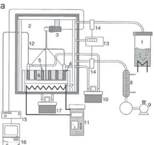
The Max-Planck institute designed and built three prototypes[18]: a steam generator (Fig. 5), a thermochemical solar plant (Fig. 6) and a solar cooking and cooling device.
The steam generator involves a MgH2/Mg heat storage. The volume
of the pressure vessel, closed to 20 L, is filled with a magnesium powder doped with a Ni powder (14.5 kg). A H2permeable tube set in
the centre of the pressure vessel allows the hydrogen supply and the hydrogen recovery. Pressurized water flowing in a helical tube is set into the metallic hydride for the heat recovery and the vapour generation. The endothermic reaction can be implemented with a ribbon heater sealed around the pressure vessel. The hydrogen produced during the endothermic reaction is stored in six commercial vessels. The operating conditions are at a maximal pressure of 50 bar, a maximal temperature of 723 K and a maximal power of 4 kW.
The thermochemical solar plant is composed of a solar radiation concentrator, a cavity radiation receiver, a Stirling engine, a hydrogen tank pressure, a heat exchanger and a MgH2/Mg storage device. The
operating temperatures range between 623 K and 723 K. During the sunshine periods, electricity is produced and heat is stored by dissociating MgH2. During the periods of weak or no solar irradiation,
the hydrogen stored is supplied to the reactor to produce heat. Then, the heat is converted into electricity by the Stirling engine.
Table 2 presents the advantages and the drawbacks of the MgH2/Mg system as a thermochemical TES system.
3.3. Carbonate systems
The general reaction form is MCO3ðsÞþ ΔHr3 MOðsÞþ CO2ðgÞ
Usually, these reactions occur at high temperature (T4723 K). The calcination/carbonation reactions are driven by the CO2partial
pressure and the temperature of the system. Two reversible reactions, the calcite and the cerrusite calcination/carbonation, were studied for a TES application. Today, most studies focus on the CO2sequestration with calcium carbonate[19].
3.3.1. Calcite calcination/carbonation
The reaction is
CaCO3ðsÞþ ΔHr3 CaOðsÞþ CO2ðgÞ with ΔHr¼ 178 kJ mol" 1:
The reversibility of the reaction can be used for a TES system application, for CO2 sequestration or for limestone production.
The working temperatures range between 973 and 1273 K with CO2partial pressure between 0 and 10 bar.
Fig. 5. Steam generator process based on MgH2[13].
In the mid 70s, Barker[20] suggests to use this reaction for energy storage. His work focuses on the reversibility of the reaction. Many problems are observed with a 10 mm particle size powder due to the loss of specific surface. Indeed, a passivation layer is created during the carbonation and leads to a reaction limitation by decrease of the CO2diffusion in the particles. In order
to solve this limitation, submicron particles have been used to avoid diffusion problems and finally to improve the reaction reversibility. While the material conversion reaches 93%, another problem arises. The volumetric energetic density of the product does not exceed 10% of the theoretical value of 35.3 kWh m" 3[21].
This huge decrease comes from the diminution of the density of the product in bulk.
At the beginning of the 80s, the calcination reaction is operated in two technologies of reactor: a fluidized bed in a batch mode (Fig. 7) and a continuous rotary kiln (Fig. 8)[22]. The fluidized bed works at a temperature between 873 and 1573 K with a solar furnace useful power of 1,4 kW.
A total conversion of CaCO3is reached. The thermal efficiency,
defined as the ratio between the sum of the sensible energy and the reaction energy over the useful power given to the material during Δt, is between 20 and 40%. It is expressed as
η¼ ðmCpΔT þ nΔHrÞ=ðΔtPuÞ
Where η is the thermal efficiency ([-]), m is the initial mass of the reactant A (kg), Cp is the specific heat over the temperature range operation (kJ kg" 1
K" 1
), ΔT is the temperature difference (K), n is the mol number of reactant A (mol), ΔHr is the reaction enthalpy (kJ mol" 1), Δt is the time difference (s) and P
u is the useful power (kW).
The rotary kiln (seeFig. 8) works at a temperature between 873 and 1573 K with a solar furnace useful power of 1.4 kW and is inclined 51 to the horizontal. A maximal conversion of 60% of CaCO3is experimentally reached with thermal efficiencies ranging
from 10% to 30%[22,23]. Here, the residence times reached in the reactor are included between 20 and 120 s for rotary speed from 4 to 25 tr min" 1.
In order to improve the energetic efficiency of the reactors, Flamant [22] identifies the main causes of thermal losses and suggests some technological improvements on both the fluidization distributor and the cooling system of the rotary kiln. According to these proposals, Foro[25]develops an annular continuous fluidized reactor with an electrical power of 3 kW and 1 kW of useful power. He also demonstrates the thermal decomposition feasibility in the fluidized bed.
After many years without surveys, Kyaw et al. [26] realise a thermogravimetric study and suggest some new concepts for the storage system [13]. A conceptual flow diagram of CaO–CO2
Fig. 6. Thermochemical solar plant[13].
Table 2
Advantages and drawbacks of the MgH2/Mg system.
Reaction Advantages Drawbacks
MgH2þ ∆Hr3 Mg þ H2 %Reversibility of the reaction (600 cycles)
%No by-product
%Product separation (Gas-solid)
%Experiment feedback
%H2storage
%Slow reaction kinetics
%Need of Fe- or Ni-doping
%Sintering
%Operating pressure (50–100 bar)
energy storing system is evaluated[26]. Three ways are used to store CO2:
%
a compressor and a tank;%
a carbonation reaction with MgO; and%
an adsorption reaction with zeolite.The CaO–CO2–MgO system was the best system to convert heat
energy at 773 K to temperatures around 1273 K. The CaO–CO2
compressor system was the most suitable for storing and deliver-ing thermal energy at the same temperature. The efficiency of CaO–CO2-zeolite systems was strongly governed by the adsorption
power of the zeolite.
Aihara et al.[27]improved the reversibility of the reaction by doping the material with titanium oxide (CaTiO3). A
thermogravi-metric study was done and showed a stabilisation of the reversi-bility and no sintering. 10 cycles have been reached without loss of reversibility and with a global conversion rate of 65%. The operat-ing conditions for the carbonation and the calcination were respectively 1023 K in nitrogen atmosphere and 1023 K with a gas mixture of N2–CO2containing 20% of CO2.
Meier et al. [24]developed a new solar reactor based on the technology of the rotary kiln (Fig. 8). The objective was to produce calcium oxide from limestone with an available power of 10 kW. The experiments have been done with 1 to 5 mm particles size and a conversion rate of 90–98% has been reached with a thermal efficiency of 20%.
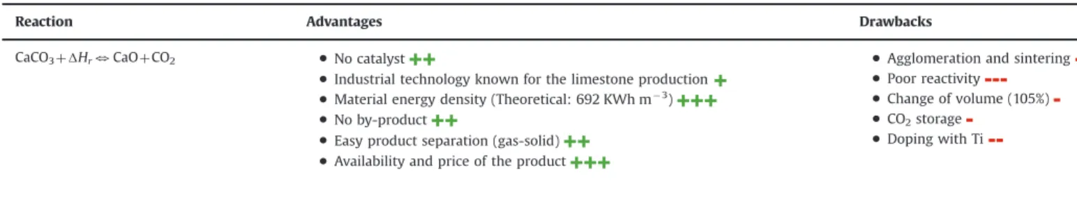
Table 3presents the advantages and the drawbacks of the CaO/ CaCO3system as the thermochemical TES system.
3.3.2. Cerrusite calcination/carbonation
The reaction scheme is
PbCO3ðsÞþ ΔHr3 PbOðsÞþ CO2ðgÞ with ΔHr¼ 88 kJ mol" 1:
This reaction was studied for chemical heat pump applications [28–30]in order to be combined with the CaCO3/CaO system. The
authors give operating temperatures from 573 to 1730 K with partial pressure of CO2included between 0 and 1 bar. A
thermo-gravimetric analysis of the PbCO3/PbO/CO2 system was done
to study the equilibrium relationship, the reaction reversibility (7 cycles of carbonation without loss of reactivity were achieved)
and the kinetics of the reaction system [29]. The following mechanism of the decomposition reaction has been proposed:
Step A: 2PbCO3¼ Pb ( PbCO3þ CO2
Step B: 3(PbO ( PbCO3)¼ 2(2PbO ( PbCO3)þCO2
Step C: 2PbO ( PbCO3¼ 3PbO þ CO2
A packed bed reactor which combined PbO and CaO was built to study the thermal storage performance of the chemical heat pump [30]. The authors showed that the heat released by carbonation of CaO was measured experimentally up to 1143 K under a reaction pressure up to 1 atm.
Table 4presents the advantages and the drawbacks of the PbO/ PbCO3system as thermochemical TES system.
3.4. Hydroxide systems
The general reaction scheme is M OHð Þ2ðsÞþ ΔHr3 MOðsÞþ H2OðgÞ
These reactions occur at medium temperature, usually 523oT o723 K. The H2O partial pressure and the temperature
drive the hydration/dehydration reactions. Fig. 9shows some of couples which could be used for a thermochemical TES application. Two reversible reactions were studied for a TES application [3,4]. These reactions are MgO/Mg(OH)2 and CaO/Ca(OH)2 hydration/
dehydration.
3.4.1. Hydration/dehydration of magnesium oxide
The reaction is
MgðOHÞ2ðsÞþ ΔHr3 MgOðsÞþ H2OðgÞ with ΔHr¼ 81 kJ mol" 1:
The preliminary studies showed that the reaction rate (forward and backward reactions) is sufficient to be used for a TES applica-tion[3,4]. This reaction couple is proposed for chemical heat pump application to store and convert heat at temperatures of 370– 440 K[32].
Ervin[3]made a cycling study over 500 cycles. He observed a conversion decrease from 95% to 60% within the fortieth cycle. It then stabilized for the next 460 cycles.
Table 3
Advantages and drawbacks of the CaO/CaCO3system.
Reaction Advantages Drawbacks
CaCO3þ ∆Hr3 CaO þ CO2 %No catalyst
%Industrial technology known for the limestone production
%Material energy density (Theoretical: 692 KWh m" 3)
%No by-product
%Easy product separation (gas-solid)
%Availability and price of the product
%Agglomeration and sintering
%Poor reactivity
%Change of volume (105%)
%CO2storage
%Doping with Ti
Table 4
Advantages and drawbacks of the PbO/PbCO3system.
Reaction Advantages Drawbacks
PbCO3þ ∆Hr3 PbO þ CO2 %No catalyst
%Material energy density (Theoretical: 300 KWh m" 3)
%No by-product
%Product separation (gas-solid)
%Poor reversibility
%Few experiment feedback
%CO2storage
The following studies have been done in a Japanese laboratory of the institute of Tokyo, the nuclear reactors laboratory. These researches aimed at developing chemical heat pumps. The first kinetic study of the hydration reaction was led by Kato et al.[33] for 10 μm particles. A 4 steps mechanism between MgO(s) and
H2O(g) has been proposed: (i) containment of water as fixed
structural, (ii) physical adsorption of water, (iii) chemical reaction with water producing Mg(OH)2(s)and (iv) inert portion of water.
The kinetic parameters have been assessed and the model shows a good accuracy with the experimental results.
Kato et al.[13]led a reversibility study in a thermobalance with a 10 nm Mg(OH)2powder[32]. In order to get a durable reversibility of
the reaction, the authors concluded that the system temperature had to be between 363 and 383 K and the water partial pressure between 47.4 and 57.8 kPa. They observed a constant reversibility with a conversion rate of 50%.
Kato et al. [34,35]have also developed a packed bed reactor used as a chemical heat pump (Fig. 10).
The packed bed (1.8 kg Mg(OH)2) was suspended to a balance
in order to measure the mass change of the bed during the reaction. An evaporator and a vacuum pump controlled the water partial pressure in the system. A heating tube controlled the temperature in the system. The operating conditions of dehydra-tion reacdehydra-tion were a temperature of 703 K and a water partial pressure of 14.7 kPa. Regarding the hydration reaction, several water pressures were tested: 31.2, 47.4 and 70.1 kPa. The results showed the possibility to use the chemical heat pump to produce heat at 383 K.
In 2005, Kato et al.[36]developed a new heat pump which is able to operate with partial steam pressure from 30 to 203 kPa. Higher pressures increase the return temperature during the hydration reaction. Here, 52 kg of Mg(OH)2 are introduced in
Fig. 9. Equilibrium relationship for metal oxide/water reactions systems[26].
Fig. 7. Solar fluidized bed reactor[19].
the reactor which is heated by an electrical resistor during the dehydration reaction. For the hydration reaction, the study of the influence of steam partial pressure underlines that for a steam pressure of 203 kPa, the temperatures in the reactor were close to 473 K. Later, the works[31,37–39]dealt with the shaping and the doping of the material in order to diminish the costs and the minimum temperature for dehydration. To reduce the price of Mg (OH)2, the authors used magnesium hydroxide of sea water
which they have purified and obtained a cost divided by 10. Concerning the doping, the authors used Ni and LiCl and a decrease of the dehydration temperature of Mg(OH)2 (around
100 K) was observed.
Table 5presents the advantages and the drawbacks of the MgO/ Mg(OH)2system as thermochemical TES system.
3.4.2. Hydration/dehydration of calcium oxide
The reaction is[40]:
Ca OHð Þ2ðsÞþ ΔHr3 CaOðsÞþ H2OðgÞ with ΔHr¼ 104 kJ mol" 1
The operating temperatures range from 623 to 1173 K with steam partial pressures from 0 to 2 bar. Many authors studied this reaction for many applications: heat pump, heat storage of con-centrated solar plants, motors preheating or electrical generation on the moon. In the following sub-sections, these works are classified into two categories: the heat pumps and the thermal energy storage.
3.4.2.1. The heat pumps. Matsuda et al.[41]studied the kinetics of
both the Ca(OH)2 dehydration and the CaO hydration in a
thermogravimetric apparatus for heat pump applications. The study have been done with 5 μm Ca(OH)2particles and 10 mg of
product. The following table lists the range of temperature and steam partial pressure for both hydration and dehydration reactions.Table 6
From the end of the 90s to the beginning of the 2000s, most of the studies have been carried out in a Japanese institute, the Kyushu Institute of Technology (KIT) ([41–47]). These works allowed developing and simulating the chemical heat pumps using the couple CaO/Ca(OH)2. These heat pumps work in closed
Fig. 10. (a) Laboratory-scale chemical heat pump; (b) reactor bed design[30].
Table 5
Advantages and drawbacks of the MgO/Mg(OH)2system.
Reaction Advantages Drawbacks
Mg(OH)2þ ∆Hr3 MgO þ H20 %No catalyst
%Material energy density (Theoretical: 380 KWh m" 3)
%Operating pressure (1 bar)
%Good reversibility of the reaction
%No by-product
%Product separation (gas-solid)
%No toxicity
%Experimental feedback (10 years)
%Availability and price of the product
%Change of volume
%No industrial feedback
%Product reactivity (50%)
%Doping
%Low thermal conductivity
Table 6
Range of temperature and steam partial pressure for both hydration and
dehydra-tion reacdehydra-tions for the kinetic study of Mastuda et al.[41].
Reaction Temperatures (K) Steam concentration (vol%)
Dehydration 693–723 1.5–6%
system and Fig. 11 presents the principle and the operating schemes.
3.4.2.2. The thermal heat storage. Ervin[3]was the first to suggest
using this reaction in a thermal energy storage plant. He achieved 290 cycles with an average conversion rate of 95%. Kanzawa and Arai [48] developed a fixed bed reactor. To increase the heat transfer during the Ca(OH)2dehydration, they proposed to use a
reactor with copper fins. They made a 2D unsteady state model for the fixed bed and determined the optimal distance between the copper fins. Darkwa[49]aimed at developing an energy storage system for the preheating of motors. Experimental and numerical studies have been carried out and he underlined the fact that the heat transfer into the installation limits the reaction. Azpiazu et al. [50]studied the reversibility in a fixed bed reactor with copper fins and 20 cycles were achieved. They observed that using an air atmosphere causes the apparition of a side reaction: the calcium oxide carbonation.
The following studies focus on the development of a thermo-chemical storage system for applications in solar plants.
Wereko-Brobby [51] worked on the feasibility of the storage system applied to a 1 MWh concentrated solar plant. He suggested using a fluidized bed reactor and he obtained a storage system yield of 45% with reactant storage temperature of 298 K. Brown et al.[52]carried out a technical-economic survey on the devel-opment of a thermochemical storage process. The results demon-strate the feasibility of the process for a solar plant with an energy efficiency of 80% and an initial price for the installation of 45 $ kWh" 1
th . Fujii et al.[53]achieved a study on the kinetics of
the particles of calcium hydroxide and calcium oxide as pellets and spheres. The work has been realized with pure products (spheres and pellets) and doped products (pellet) with copper, zinc and aluminum. The best results, for the reaction kinetics are obtained with aluminum doping for an optimal concentration of 15% in weight. Between 2010 and 2013, Schaube et al.[54,55]carried out a survey on the feasibility of the storage process in a thermo-dynamical solar plant. They used a fixed bed reactor and simulated a one dimensional chemical reactor in unsteady state. They concluded that the heat transfer between the bed and the wall was not a viable solution because the heat conductivity of the material is too low. To improve the heat transfer, they suggested using the circulating gas into the reactor as the heat transfer fluid. In 2012, Schaube et al. [56] worked on the physic-chemical
characterization of the products. The authors determined the particles diameter, the specific heat, the reaction enthalpy and the kinetics of both hydration and dehydration with a thermo-gravimetric analysis. They achieved 100 cycles without reversi-bility loss. Later, Schaube et al. [57,58] led experimental and numerical studies on the technology of the fixed bed reactor. They used the reactor presented onFig. 12for the experimental part and achieved 25 cycles without reversibility loss. The numerical model in two dimensions and in unsteady state has been developed with the COMSOL software. The authors obtained a good accuracy between the simulated and the experimental results.
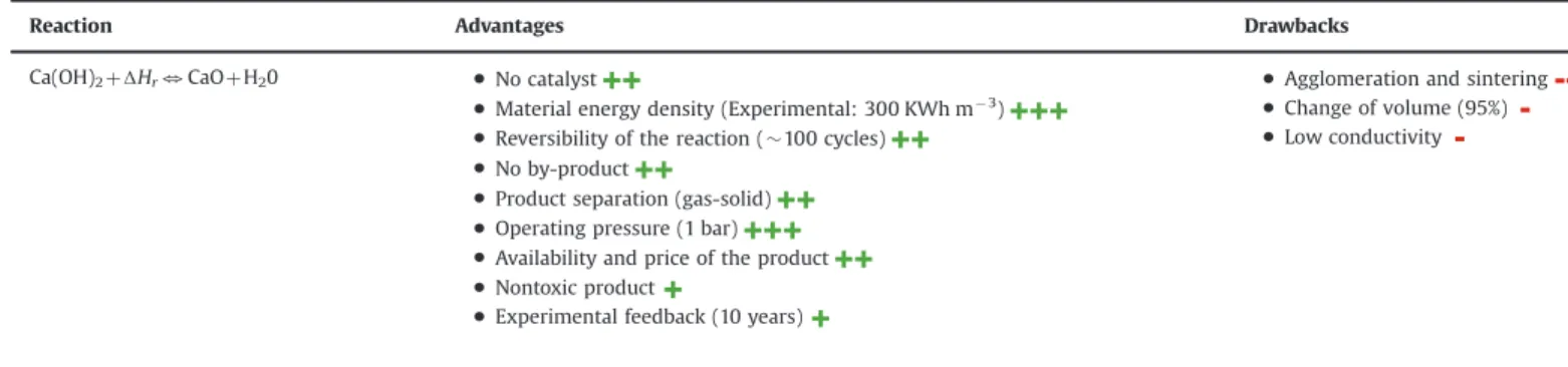
Table 7presents the advantages and the drawbacks of the CaO/ Ca(OH)2system as a thermochemical TES system.
3.5. The REDOX system
The general reaction form is MxOyðsÞþ ΔHr3 xMðsÞþ y=2O2
These reactions occur at temperatures between 623 and 1373 K. Only few studies have been made on these materials. The first studied couple was BaO2/BaO in 1978[59]and after 30 years without
survey, DLR is interested again in these systems for storage applica-tion in tower centrals.
3.5.1. Oxidation/decomposition of barium peroxide
The reaction is
2BaO2ðsÞþ ΔHr3 2BaOðsÞþ O2ðgÞ with ΔHr¼ 77 kJ mol" 1:
This reaction occurs at temperatures between 673 and 1300 K for partial oxygen pressure between 0 and 10 bar. Preliminary thermogravimetric studies showed the potential of BaO/BaO2
system for a thermochemical TES application [59,60]. Some difficulties arose when trying to achieve the complete conversion of reaction, because of mass transfer limitations and a crusting of the material surface [60]. The kinetic equations of both forward and reverse reactions were determined and the reaction reversi-bility had shown a decrease after the first cycle [59]. Recently, Wong et al.[60]studied this couple and compared it with other redox couples for a feasibility study in tower centrals
Fig. 12. Experimental setup of a laboratory scale of the DLR system[34].
Table 8presents the advantages and the drawbacks of the BaO/ BaO2system as thermochemical TES system.
3.5.2. Other oxidation/decomposition peroxide couples
More recently, a study about the potential of six oxide/peroxide couples for a thermochemical TES application has been investi-gated by Wong et al. [61]. To assess the relevance of various couples, a thermodynamic analysis, an engineering feasibility study and thermogravimetric measurements have been done. The relevant couples are: Co3O4/CoO, MnO2/Mn2O3, CuO/Cu2O,
Fe2O3/FeO, Mn3O4/MnO and V2O5/VO2. Nevertheless, for their
application, the most promising reaction is:
2Co3O4ðsÞþ ΔHr3 6CoOðsÞþ O2ðgÞ with ΔHr¼ 205 kJ mol" 1:
The decomposition occurs at 1123 K in a nitrogen atmosphere and the oxidation occurs at 973 K in an air atmosphere with partial oxygen pressure between 0 and 1 bar. This reaction has been implemented both in a thermogravimetric balance and in a fixed bed[62]. 500 cycles have been achieved and the morphologic study of the product showed a progressive magnification of the particles progressively during the cycles. Buckingham et al. [63] have done a numerical analysis of packed bed parameters and operating conditions. They
Table 8
Advantages and drawbacks of the BaO/BaO2system.
Reaction Advantages Drawbacks
2BaO2þ ∆Hr3 2BaO þ O2 %Operating temperature (400–1300 K)
%O2reactant
%No catalyst
%No side reaction
%Products separation (gas-solid)
%Operating pressure (0–10 bar)
%Incomplete conversion of both forward and reverse reactions
%No experiment feedback
Table 9
Advantages and drawbacks of the Co3O4/CoO system.
Reaction Advantages Drawbacks
2Co3O4þ ∆Hr3 6CoO þ O2 %High reaction enthalpy ( $ 205 kJ mol" 1)
%O2as a reactant
%No catalyst
%No by product
%Reversibility (500 cycles)
%Products separation (gas-solid)
%Few experiment feedback
%Storage of O2
%Toxicity of the products
%Cost of the products
Table 7
Advantages and drawbacks of the CaO/Ca(OH)2system.
Reaction Advantages Drawbacks
Ca(OH)2þ ∆Hr3 CaO þ H20 %No catalyst
%Material energy density (Experimental: 300 KWh m" 3)
%Reversibility of the reaction ($ 100 cycles)
%No by-product
%Product separation (gas-solid)
%Operating pressure (1 bar)
%Availability and price of the product
%Nontoxic product
%Experimental feedback (10 years)
%Agglomeration and sintering
%Change of volume (95%)
%Low conductivity
Table 10
Advantages and drawbacks of the NH4HSO4/NH3/H2O/SO3system.
Reaction Advantages Drawbacks
NH4HSO4þ ∆Hr 3NH3þ H2OþSO3 %Material energy density (Theoretical: 860 KWh m" 3)
%No catalyst
%Product separation (gas-liquid)
%Corrosive products
%Toxic products
concluded that a packed bed design for metal oxide TES couple will not be economically competitive and recommended to study a “moving bed” design, as a rotary kiln, to improve the TES process.
Neises et al.[64]used a rotary kiln based on the work of Buckingham et al.[63]to implement the reaction which is heated through a solar furnace of 22 kW. They carried out a reversibility study on three samples: pure Co3O4and two mixtures of doped Co3O4with alumina
oxide. They achieved 30 cycles and demonstrated the feasibility of the process with an energetic density in the reactor of 95 kWh m" 3
. Table 9 presents the advantages and the drawbacks of the Co3O4/CoO system as the thermochemical TES system.
3.6. Ammonia system
Historically, two reactions using the “Ammonia system” have been studied. The first one, studied by Wenthworth et Chen[5]is the decomposition of NH4HSO4 but only few surveys have been
carried out. The second one, studied by the Australian National University (ANU) since 40 years, is the decomposition/synthesis of the ammonia for thermal energy storage.
Fig. 14. Solar ammonia dissociation reactor (a) design of the cavity receiver with 15 kWsoland its assembly on ANU0s 20 m2dish without insulation fitted; and (b) reactor in
operation on the ANU0s 20 m2dish[49].
Fig. 13. Installation of a parabolic through power plant with chemical energy
storage[49].
3.6.1. The ammonium hydrogen sulfate system
The reaction is
NH4HSO4ðlÞþ ΔHr3 NH3ðgÞþ H2OðgÞþ SO3ðgÞ with ΔHr¼ 336 kJ mol" 1:
A preliminary study showed the potential of this system for TES application [5]. The reaction occurs at 690 K and 1.46 atm. No catalysts are required for both forward and reverse reactions. A process flowsheet was designed to carry out a thermochemical TES process based on ammonium hydrogen sulfur cycle [5]. Prengle et al. [5] defined the thermal efficiency as the ratio between the released heat energy and the required solar energy. The preliminary energy analysis of the cycle confirmed the engineering feasibility of the process with a thermal efficiency of 62% and a theoretical energetic density of 860 kWh m" 3.
Table 10 presents the advantages and the drawbacks of the NH4HSO4/NH3/H2O/SO3system as the thermochemical TES system.
3.6.2. Dissociation/synthesis of NH3
The reaction is
2NH3ðgÞþ ΔHr3 N2ðgÞþ 3H2ðgÞ with ΔHr¼ 66:9 kJ mol" 1:
This reaction occurs at temperatures between 673 and 973 K and pressures between 10 and 30 bar. The Haber–Bosch process is based on this reaction for the NH3 production since 100 years. A lot of
Fig. 16. ANU0s 500 m2paraboloidal dish concentrator[57].
Fig. 17. Schematic diagram of the EVA-ADAM process cycle for heat conversion and transportation of nuclear energy[58].
Table 11
Advantages and drawbacks of the NH3/N2/H2system.
Reaction Advantages Drawbacks
2NH3(g)þ ∆Hr3 N2(g)þ 3H2(g) %Ammoniac synthesis known since 100 years (Haber-Bosch process)
%Ammoniac: liquid at ambient conditions
%ANU0s important experiment feedback (40 years)
%No side reaction
%H2and N2storage (gases)
%Use of catalyst (Fe/Co)
%Operating pressure (80–200 bar)
%Incomplete conversion of both forward and
reverse reactions
studies (e.g.: kinetic studies by Temkin et al.[65]) have already been done for this application (NH3production).Fig. 13shows the scheme
of the installation developed and used by the Australian National University (ANU) for a thermochemical TES application.
Both forward and reverse reactions are catalysed. The catalyst materials used in the endothermic reactor and in the exothermic reactor are respectively the Haldor-TopsǾe “DNK-2R” [66] and Haldor-TopsǾe “KM1”[67].
The works on a thermochemical TES system using the ammo-nia system began with Carden[68]and Williams and Carden[69]. They assessed a theoretical energetic efficiency of 90% if the conversion rate of the ammonia into the reactor was higher than 60%. Later, the thermodynamic limitations associated with the use of the reversible reaction of the ammonia have been studied by Lovegrove et al. [70,71] thanks to a pseudo-homogeneous two dimensions model of reactor. The first solar driven high pressure ammonia reactor of 1 kW has been successfully tested in a closed loop system[67]. This reactor allowed the validation of a numer-ical model to predict the temperatures in the catalyst, on the wall and in the gas, and also the conversion rate and the product flowrates. A detailed study of a 10 MWebase load power plant in
Australia, has indicated that levelled electricity costs lower than AUS $ 0.15/kWh were potentially achievable [72]. A scale-up (Fig. 14) of the first solar driven ammonia reactor has been done in order to accept the full (¼15 kW) input from the ANU0s 20 m2
dish system[66].
Fig. 15 shows the design of the ammonia synthesis heat recovery reactor of 10 kWth[66].
A new 500 m2parabolic dish solar concentrator has been built by the ANU in 2009 (Fig. 16). The receiver geometry was numeri-cally optimized to improve the dissociation reaction [73]. This numerical model can then be applied to develop an ammonia receiver for the 500 m2SG4 dish concentrator.
ANU has done the most advanced works in this sector, by working for over 40 years on the thermochemical energy storage using the dissociation and synthesis of ammonia. ANU is also the first laboratory which continuously store and release energy during 24 h thanks to its closed loop system composed of a solar reactor of 15 kW for the dissociation reaction and a synthesis reactor of 10 kW[75].
Table 11 presents the advantages and the drawbacks of the NH3/N2/H2system as the thermochemical TES system.
3.7. Organic systems 3.7.1. Methane reforming
Reforming of methane using steam or carbon dioxide is industrially used for the H2production. These reactions have also
been studied for heat transportation. There is no study about the TES system based on the methane reforming, but this could be an application. Both reactions are catalysed by Ni-based or Ru-based catalysts[76].
3.7.1.1. Methane steam reforming. The reaction is
CH4ðgÞþ H2OðlÞþ ΔHr3 COðgÞþ 3H2ðgÞ with ΔHr¼ 250 kJ mol" 1CH4:
The side reaction is
COðgÞþ H2OðlÞ3 CO2ðgÞþ H2ðgÞþ ΔHr with ΔHr¼ " 41:2kJ mol" 1CO:
This reaction occurs at temperatures between 873 and 1223 K and pressures between 20 and 150 bar. In 1975, Kugelers et al.[77] suggested to use the reaction of methane steam reforming for the transport of the thermal energy coming from the nuclear plants. The authors made a feasibility survey and proposed a process flowsheet (Fig. 17) with energetic efficiencies between 60% and 73%. In order to study and understand the phenomena involved during the reaction, a first pilot plant, EVA I, was built by Fedders et al. [78]. An industrial-scale pilot plant EVA I/ADAM I of 300 kW was developed in 1979 at the Intitut für Reaktorbauelemente in Germany. 850 operating hours have been investigated. They showed the feasibility of the energy transport system by means of the reversible reaction [79]. More recently, a new design process (ICAR: immediate catalytic accumulation of ionizing radiation energy) was developed by Aristov et al [80]. The endothermic reactor is directly combined with the nuclear reactor to improve the process efficiency.
3.7.1.2. Methane reforming using carbon dioxide. Methane
refor-ming using carbon dioxide presents an advantage for a TES
Fig. 19. Schematic of the solar chemical receiver–reactor[64].
Table 12
Advantages and drawbacks of the CH4/CO2and the CH4/H2O systems.
Reaction Advantages Drawbacks
CH4þ H2Oþ ∆Hr3 3H2þ CO %Industrial feedback
%High reaction enthalpy ( $ 250 kJ mol" 1)
%Gas phase %H2storage %Cost of CH4 %Side reactions %Use of catalyst %Low reversibility CH4þ CO2þ ∆Hr3 2H2þ 2CO
application compared to the steam reforming process. It does not involve water evaporation[76].
The carried out reaction is
CH4ðgÞþ CO2ðgÞþ ΔHr3 2COðgÞþ 2H2ðgÞ with ΔHr¼ 247 kJ mol" 1CH4:
The side reaction is:
CO2ðgÞþ H2ðgÞþ ΔHr3 COðgÞþ H2OðgÞ with ΔHr¼ " 41:2 kJ molCO" 1:
Fig. 18 shows the process flowsheet. During the endothermic reaction, methane and carbon dioxide are decomposed at a temperature between 973 and 1133 K and absolute pressure of 3.5 bar to form hydrogen and carbon monoxide. Edwards and Maitra [81] outlined the potential of this reforming for TES application. Edwards et al. [82] achieved a technical-economic survey in order to evaluate the energetic efficiencies of two different processes for a production of 100 MWe. The first one works in closed loop (Solar/Rankine cycle plant) and the second one in open loop (Solar/Gas turbine combined cycle). Both cases have energetic efficiencies of 33.6% and 44.6%.
Later, the DLR [83] developed a solar reactor of 300 kW to implement the reforming reaction (Fig. 19). This solar reactor has been used in a global test loop at the WIS (Weizmann Institute of Science) in Rehovot, Israel. Nevertheless, in spite of good conver-sion rate of methane, many problems of catalyst deactivation appeared due to a deposit of sodium.
Table 12 presents the advantages and the drawbacks of the CH4/CO2and the CH4/H2O systems as thermochemical TES system.
3.7.2. Cyclohexane dehydrogenation – benzene hydrogenation
The carried out reaction is
C6H12ðgÞþ ΔHr3 C6H6ðgÞþ 3H2ðgÞ with ΔHr¼ 206 kJ mol" 1:
This reaction is well known in the chemical industry and the reactor technologies to carry out both forward and reverse reactions are known. During the charging step, the cyclohexane is heated up to 566 K at 1 bar at which the endothermic reaction occurs. The decomposition reaction products are hydrogen (gas) and benzene (gas). During the storing step, benzene can be stored as a liquid at atmospheric pressure and hydrogen has to be compressed and stored. During the discharging step, benzene and hydrogen are mixed at 610 K and 70 bar to generate heat and the initial cyclohexane. Both forward and reverse reactions are catalysed[4]. Process simulations of
chemical heat pumps were investigated to improve the coefficient of performance (COP)[80,84].
Table 13 presents the advantages and the drawbacks of the C6H12/C6H6system as the thermochemical TES system.
Table 13
Advantages and drawbacks of the C6H12/C6H6system.
Reaction Advantages Drawbacks
C6H12þ ∆Hr3 C6H6þ 3H2 %Industrial feedback %Operating temperature ($ 580 K) %H2storage %Use of Catalyst %Secondary reaction %Toxic products %Reversibility Table 14
Advantages and drawbacks of the SO3/SO2/O2system.
Reaction Advantages Drawbacks
2SO3þ ∆Hr3 2SO2þ O2 %Industrial feedback with the H2SO4production
%Operating temperature (773–1223 K) %O2as a reactant %Corrosive product %Toxic product %Need of catalyst %Storage of H2
Fig. 20. Energy density versus turning temperature for the reversible reactions studied as a TES system in the literature: (a) volumetric energy density; and (b) mass energy density.
T able 1 5 Lit er atur e data about rev ersible rea ctions studied for thermochemical stor ag e sy stems (t emper atur e range of 5 7 3– 1 2 7 3 K). R eaction Phase R eaction enthalp y (kJ/ mol A ) Opera ting tempera tur e conditions Energ etic density R elat ed w or ks T echnology R eferen ces Hydride sy stem MgH 2 þ ∆ Hr 3 Mg þ H2 Solid-gas ∆ Hr ¼ 75 kJ/mol Heat Charge: 653 K Heat relea se: 503 K – 580 kWh/m 3 MgH2 – 0.80 kWh/kg MgH2 – Kinetic study – R ev ersibility study – R eact or design – heat e x chang er design – R evie w – S team g ener at or (3.6 kWh) – Pac ked bed react or – Solar po w er station – Solar cooking and cooling device – Heat e x chang er [1 7,1 8] Carbonate sys tem PbC O3 þ ∆ Hr 3 PbO þ CO 2 Solid-gas ∆ Hr ¼ 88 kJ/mol – Heat charg e: 7 23 K – Heat R elease: 5 7 3 K – 303 kWh/m 3 PbCO3 – 0.09 kWh/kg – Eq uilibrium relationship – Kinetics study – TG A (thermogr avimetric anal ysis) [28 – 30] CaCO 3 þ ∆ Hr 3 CaO þ C O2 Solid-gas ∆ Hr ¼ 178 kJ/mol – Heat charg e: 11 3 3 K – Heat release: 11 53 – 692 kWh/m 3 CaCO 3 – 0.49 kWh/kg CaCO3 – R ev ersibility – R eacti vity – R eact or design – Decarbonation react or – C O2 capt ure – R evie w – TG A – Fluidised bed react or – Pac ked bed react or – Chemical heat pump – Horizontal rot ary react or [1 3,1 9– 2 7] Hydr o xide sys tem Mg(OH) 2 þ ∆ Hr 3 MgO þ H2 O Solid-gas ∆ Hr ¼ 81 kJ/mol – Heat charg e: 423 K – Heat release: 3 7 3 K – 388 kWh/m 3 Mg(OH) 2 – 0.39 kWh/kg Mg (OH)2 – Eq uilibrium relationship – Kinetic study – R ev ersibility – R eact or design – TG A – Pac ked bed react or – Chemical heat pump [3,4,3 1– 36] Ca(OH) 2 þ ∆ Hr 3 CaO þ H2 O Solid-gas ∆ Hr ¼ 1 04 kJ/mol – Heat charg e: 7 23 K – Heat release: 298 – 6 7 3 K – 43 7 kWh/m 3 Ca(OH)2 – 0.39 kWh/kg Ca (OH)2 – Eq uilibrium relationship – Kinetic study – R ev ersibility – R eact or design – Simulation – Heat tr ansfer enhancement – Cost anal ysis – TG A – Pac ked bed react or – Chemical heat pump [3,4,40 – 58] Ammonium sy stem NH 4 HSO 4 þ ∆ Hr 3 NH 3 þ H2 O þ SO 3 Liq uid-gas ∆ Hr ¼ 3 36 kJ/mol – Heat charg e: 1 20 0 K – Heat release: 7 0 0 K – 860 kWh/ m 3 NH4HSO4 – 0.81 kWh/ kg NH4HSO4 – Theor etical anal y sis – Thermodynamics anal y sis – Pr ocess simulation [– ] [4,5] 2NH 3(g) þ ∆ Hr 3 N2(g) þ 2H 2(g) Gas ∆ Hr Heat Charg e ¼ 66.9 kJ/ mol ∆Hr Heat R elease ¼ 53 kJ/mol Heat charg e: 7 23 K; P ¼ 9– 1 50 bar Heat relea se: 7 23 K; P ¼ 1 0– 30 0 bar 7 45 kWh/m 3 NH3(l) 1.09 kWh/kg NH3(l) – Kinetic study – Pr ocess simulation – T echnical and economical feasibility study – R eact or design study – Ammonia receiv er design – 1 kW chem. Labor at ory -scale ammonia dissociation and synthesis react or – 1 0 kW chem. Labor at ory-scale ammonia dissociation and synthesis react or – Ammonia receiv er design for a 50 0 m ² dish [4,65 – 7 4,87 – 89]
REDO X sy stem 2Co 3 O4 þ ∆ Hr 3 6CoO þ O2 Solid-gas ∆ Hr ¼ 205 kJ/mol T ¼ 11 43 – 11 7 3 K – 295 kWh/m 3 Co3O4 – 0.24 kWh/kg Co3O4 – Eq uilibrium anal y sis – Kinetic study – Mix ed o xide reaction – Thermodynamic anal y sis – TG A – Pa ck ed bed react or [6 1,63] 2BaO 2 þ ∆ Hr 3 2BaO þ O2 Solid-gas ∆ Hr ¼ 7 7 kJ/mol T ¼ 963 – 1 053 K – 328 kWh/m 3 BaO2 – 0. 1 3 kWh/kg BaO2 – Eq uilibrium anal y sis – Kinetic study – TG A [59,60] Organic sy stem CH 4 þ H2 O þ ∆ Hr 3 3H 2 þ C O Gas 250 kJ/mol – Heat charg e: 1 223 K – Heat release: 803 K – 7.8 kWh/m 3 CH4(g) – 4.34 kg/kg CH4(g) – Pr ocess simulation – R eact or design – Kinetic study – Energy tr ansport – Labor at ory pilo t plant – Industrial size pilot plant 30 0 kW transport ed (EVA I/AD AM I) [7 6– 80] CH 4 þ C O2 þ ∆ Hr 3 2H 2 þ 2C O Gas 2 4 7 kJ/mol – Heat charg e: 1 223 K – Heat release: 803 K – 7.7 kWh/m 3 CH4(g) – 4.28 kg/kg CH4(g) – T echnical and economical feasibility study – R eact or design – Energy tr ansport – Design of the receiv er react or 20 0– 30 0 kW (DLR) [7 6,79,81 – 83] C6 H1 2 þ ∆ Hr 3 C6 H6 þ 3H 2 Liq uid-gas ∆ Hr ¼ 206.7 kJ/mol Heat charg e: T ¼ 590 K Heat release: T ¼ 6 7 0 K 530 kWh/m 3 C6H1 2(l) 0.68 kWh/kg C6H1 2(l) – Pr ocess simulation anal y sis in chemical heat pump [– ] [4,80,84] SO 3 sy stem 2SO 3 þ ∆ Hr 3 2SO 2 þ O2 Liq uid-Gas ∆ Hr ¼ 98 kJ/mol Heat charg e: 1 0 7 3– 1 2 7 3 K Heat release: 7 7 3– 87 3 K 646 kWh/m 3 SO3(l) 0.34 kWh/kg SO3(l) – Pr ocess anal ysis to pr oduce a continuous 1 0 0 MW electric po we r output [– ] [4,85]
3.7.3. Thermal dissociation of sulfur trioxide
The reaction is
2SO3ðgÞþ ΔHr3 2SO2ðgÞþ O2ðgÞ with ΔHr¼ 98 kJ molso" 13ðGÞ:
This reaction occurs at temperatures between 773 and 1373 K for pressures between 0.1 and 0.5 MPa. During the charging step, the liquid sulfur trioxide is heated up to vaporization. This phase change requires 43 kJ mol" 1
SO3 lð Þ. The gas product is heated up to
the decomposition temperature (1073–1373 K), at which the endothermic reaction occurs. The endothermic reaction has to be catalysed, generally with V2O5[4,85]. The decomposition reaction
products are sulfur dioxide (gas) and oxygen (gas). During the discharging step, the oxygen is added to the sulfur dioxide to regenerate the heat (773–973 K) and the initial sulfur trioxide. A process analysis has been done by Chubb[85]to use this reaction in a Solchem system to produce a continuous 24 h electricity output of 100 MW with a 72 h storage. A process simulation assessed the thermal efficiency to 58%[4].
Table 14presents the advantages and the drawbacks of the SO3/
SO2/O2system as the thermochemical TES system.
3.8. Summary of case studies
Several numerical, experimental and technological studies concerning thermochemical energy storage have been found in the literature.Fig. 20a and b plot the volumetric energy density and the gravimetric energy density versus the turning tempera-ture of the studied reactions. To assess the volumetric energy density of the solid reactant, the bulk density with a packed bed porosity of 0.5 has been chosen. Usually, a packed bed porosity of spherical particle is between 0.4 and 0.5[86]. The volume of pores inside a particle is considered to be equal to zero.
Fig. 20 is extremely useful to quickly screen the candidate reactions in the desired temperature and the energy density ranges. Each reaction system is detailed inTable 15.Table 15lists the reversible reaction, the phase of the A reactant, the reaction enthalpy by mol of reactant A, the operating temperatures, the energy density and the related works and technologies.
4. Conclusion
This paper presents a state of the art of the current numerical and experimental researches on chemical reactions for high temperature thermochemical heat energy storage. Most of the described systems were only tested on laboratory scale until now. This paper has also offered an updated review of the high temperature (573–1273 K) thermochemical TES system which have the potential to become an important part of sustainable handling of energy in a close future. The following conclusions that can be drawn are
%
The energy density of a thermochemical TES system ($ 500 kWh m" 3) is 5 to 10 times higher than latent heatstorage systems and sensible heat storage systems respectively.
%
Thermochemical TES systems appear to be the most promising way to store solar thermal energy during a long-term period. Indeed, both storage period and transport distance are theoreti-cally unlimited because there is no loss of thermal energy during storage as products can be stored at ambient temperature.%
Laboratory-scale experiments, numerical and technological studies have demonstrated the feasibility of several reaction systems for a TES application.%
The system involving the ammonia dissociation and synthesis is the most mature technology for a high temperatureTES application with 40 years of researches and pilot-scale equipment.
%
The dehydration/hydration of the Ca(OH)2/CaO couple shows ahigh potential for TES application but future works need to focus on the intensification of heat and mass transfers inside the reactor.
%
For a high temperature thermochemical heat storage (CSP application), the following chemical reactions seem to be the most interesting ones in terms of actual development, cost and temperature range:MgH23 Mg þ H2
PbCO33 PbO þ CO2
CaðOHÞ23 CaO þ H2O
NH33 N2þ H2
Nowadays, the storage system with the reaction couple NH33 N2þ H2 is the most mature one especially with the ANU
works and their 40 years feedback. Nevertheless, recently the reaction couple Ca(OH)23 CaO þ H2O appears to be promising for
thermochemical heat storage and many studies and projects contribute to develop this system. The main barriers to remove are linked to the reactor heat and mass transfers. As a consequence the development of intensified heat exchanger/reactor could be interesting to study. Mass transfer issues have also to be addressed, especially if fast hydration and dehydration kinetics are expected. A compromise between particle diameter and mass transfer limitation will have to be found and future works could focus on the functionalization of the particles, supported particles or doping. Moreover, for G/S reactions in general, an effort should be done on the optimization of the particle size and the reaction bed structure to guarantee a constant heat output during the discharging step. This optimization must be done without com-promising, as far as possible, the system compactness.
Another area of research is the optimization of the temperature level during charging/discharging steps. The objective is to dimin-ish the difference of temperature between both steps to improve the efficiency and the ease to control the process and the down-stream turbine for instance.
At present, only laboratory and pilot experiments have been done and scale-up is an important point to address. Large-scale experiments are necessary to prove the feasibility of the thermo-chemical TES system for both short and long-term storage. The process must be reversible with a constant conversion rate and without degradation after a large number of cycles. To support the scale-up procedure, numerical models of the storage process have to be developed. The objective is to insert them in the whole power plant scheme to assess the performances according to the application case (seasonal storage, 24 h electricity production, peak load,…).
The future works should also allow the definition of a meth-odology to choose suitable materials for a given TES application. Technical-economic studies will be required to assess the profit-ability of the whole TES process. Thus, storage materials, storage equipment, control strategies of the system and applications cases are important points to address.
References
[1]Gil A, Medrano M, Martorell I, Lazaro A, Dolapo P, Zalba B, et al. State of the art on high temperature thermal energy storage for power generation. Part 1 – concepts, materials and modelisation. Renew Sust Energy Rev 2010;14 (1):31–55.
[2]Medrano M, Gil A, Martorell I, Potau X, Cabeza LF. State of the art on high-temperature thermal energy storage for power generation. Part 2 – case studies. Renew Sust Energy Rev 2010;14(1):56–72.

![Fig. 5. Steam generator process based on MgH 2 [13].](https://thumb-eu.123doks.com/thumbv2/123doknet/3240618.92880/6.892.485.784.228.953/fig-steam-generator-process-based-mgh.webp)
![Fig. 9. Equilibrium relationship for metal oxide/water reactions systems [26]. Fig. 7](https://thumb-eu.123doks.com/thumbv2/123doknet/3240618.92880/9.892.77.814.294.1172/fig-equilibrium-relationship-metal-oxide-water-reactions-systems.webp)

![Fig. 13. Installation of a parabolic through power plant with chemical energy storage [49].](https://thumb-eu.123doks.com/thumbv2/123doknet/3240618.92880/13.892.148.732.788.1144/fig-installation-parabolic-power-plant-chemical-energy-storage.webp)
![Fig. 18. Schematic diagram of reforming methane process cycle using carbon dioxide for heat conversion and transportation of concentrated solar energy [58].](https://thumb-eu.123doks.com/thumbv2/123doknet/3240618.92880/14.892.214.699.903.1131/schematic-diagram-reforming-methane-process-conversion-transportation-concentrated.webp)

![Correction to "Analysis and Optimization of Sleeping Mode in WiMAX via Stochastic Decomposition Techniques" [Sep 11 1630-1640]](data:image/gif;base64,R0lGODlhAQABAIAAAP///wAAACH5BAEAAAAALAAAAAABAAEAAAICRAEAOw==)