OATAO is an open access repository that collects the work of Toulouse
researchers and makes it freely available over the web where possible
Any correspondence concerning this service should be sent
to the repository administrator:
[email protected]
This is an author’s version published in:
http://oatao.univ-toulouse.fr/24028
To cite this version:
Nozahic, Franck
and Carabat, Alexandra Lucia and Mao, Weichen and
Monceau, Daniel
and Estournès, Claude
and Kwakernaak, Cornelis and van
der Zwaag, Sybrand and Sloof, Willem G. Kinetics of zircon formation in yttria
partially stabilized zirconia as a result of oxidation of embedded molybdenum
disilicide. (2019) Acta Materialia, 174. 206-216. ISSN 1359-6454
Kinetics
of zircon formation in yttria partially stabilized zirconia as a
result
of oxidation of embedded molybdenum disilicide
F.
Nozahic
a, b,
A.L. Carabat
c,
W. Mao
c,
D. Monceau
a,
C. Estournes
b,
C. Kwakernaak
c,
S.
van der Zwaag
d,
W.G. Sloof
c, *aCIRIMAT, Universit!e de Toulouse, CNRS, INPT, UPS, ENSIACET, 4 all!ee Emile Monso, 31030 Toulouse, France bCIRIMAT, Universit!e de Toulouse, CNRS, INPT, UPS, 118 Route de Narbonne, F-31062 Toulouse, France
cDepartment of Materials Science and Engineering, Delft University of Technology, Mekelweg 2, 2628 CD, Delft, the Netherlands dFaculty of Aerospace Engineering, Delft University of Technology, Kluyverweg 1, 2629 HS, Delft, the Netherlands
a r t i c l e
i n f o
Keywords:
Yttria patrially stabilized zirconia Molybdenum disilicide Interdiffusion
Zircon formation kinetics Self-healing
a b s t r a c t
Recently MoSi2sacrificial particles embedded in yttria partially stabilized zirconia (YPSZ) have been
proposed as attractive healing agents to realize significant extension of the lifetime of the thermally loaded structures. Upon local fracture of the YPSZ, the embedded healing particles in the path and in the vicinity of the crack react with the oxygen atoms transported via the crack and first fill the crack with a viscous glassy silica phase (SiO2). The subsequent reaction between this freshly formed SiO2and the
existing tetragonal ZrO2of the YPSZ leads to the formation of rigid crystalline zircon (ZrSiO4), which is
key in the crack-healing mechanism of YPSZ based materials. The isothermal kinetics of the self-healing reaction and the mechanism of zircon formation from the decomposing MoSi2and the surrounding YPSZ
were assessed via X-ray diffraction (XRD). The obtained results revealed that at 1100!C the reaction
between amorphous SiO2and YPSZ is completed after about 10 h. For a more accurate determination of
the kinetics of the self-healing reaction, bilayer samples of YPSZ e MoSi2(with and without boron
addition) were annealed in air over a temperature range of 1100e1300!C. This led to the formation of a
MoSi2/amorphous (boro)silica/zircon/YPSZ multi-layer, which was investigated with scanning electron
microscopy (SEM) and electron probe X-ray microanalysis (EPMA). Kinetic modeling of the growth of zircon and silica or borosilicate layers showed that zircon growth was dominated by the diffusion of Si4þ in zircon whereas the growth of the silica or borosilicate layer was controlled by oxygen diffusion. Moreover, a significant increase in the rate of ZrSiO4formation was observed due to the presence of B in
the MoSi2particles.
1. Introduction
A concept of crack-healing in yttria patrially stabilized zirconia (YPSZ, i.e. ZrO2 containing 4e5 mol % Y2O3) has been proposed,
which involves molybdenum disilicide (MoSi2) sacrificial particles
embedded in a YPSZ ceramic matrix that respond to crack forma-tion [1]. At high-temperatures in an oxidizing gas environment, the MoSi2particles in the crack path forms a glassy silica (SiO2) flowing
into the crack-gap and reconnecting the fracture surfaces. Subse-quently, the silica formed reacts with the matrix, resulting in the formation of crystalline zircon (ZrSiO4) phase which, unlike the
viscous silica, has a mechanical load bearing ability at high tem-peratures [2]. As the final healing product, ZrSiO4, is key in
re-establishing the mechanical integrity of YPSZ, the mechanism and kinetics that governs its formation is highly relevant for the effec-tive kinetics of strength restoration of damaged YPSZ and is therefore studied here.
The kinetics of silica formation as a result of MoSi2oxidation at
high-temperature is well documented, e.g. Ref. [3]. However, comprehensive knowledge on the kinetics and mechanism of the subsequent zircon formation due to SiO2 reacting with ZrO2 is
lacking. So far, only the formation of zircon from a mixture of zir-conia and silica in the form of quartz, cristobalite, tridymite and amorphous phase has been studied [4]. The reaction between zir-conia and silica requires temperatures above 1300!C and the
allotropic modification of silica has little or no effect on the final
*Corresponding author.
E-mail address:[email protected](W.G. Sloof).
degree of zircon formation [4], whereas ZrSiO4 could be formed
from an equimolar mixture of amorphous SiO2and ZrO2at 1200!C
[4,5]. Also, it has been observed that the formation of zircon from amorphous SiO2 and tetragonal zirconia (t-ZrO2) predominates
over the allotropic transformation of amorphous silica to cristo-balite [4]. In addition, only a few studies dealt with the actual re-action mechanism of zircon formation [4e6]. The available data claims that zircon precipitates at the interface between ZrO2and
ZrSiO4once the solubility limit of Si in zirconia is reached. However,
this is not supported yet by experimental evidence like element concentration profiles along the ZrSiO4layer. A complete
descrip-tion of the reacdescrip-tion kinetics between ZrO2 and SiO2, including
determination of the activation energy of zircon formation is needed, since the existing data accounts only for the formation of ZrSiO4 starting from SiO2 (including its allotropes) and only
unstabilized zirconia.
The formation of amorphous silica covering the surface upon oxidation of MoSi2(and Mo5Si3) is promoted by addition of boron
as MoB [7e12], thereby mitigating the formation of volatile MoO3
[13]. At relatively low oxidation temperatures, in the range of 600e800!C, the formation of this gaseous MoO3is considered to be
responsible for the rapid oxidation and associate disintegration of molybdenum silicides, also known as ‘pest oxidation’ [14e16].
Recent studies have indicated that the presence of boron in the MoSi2 particles can increase the fluidity of the amorphous SiO2
formed [2,17,18], a feature which is likely to enhance the subse-quent reaction kinetics of SiO2with the ZrO2being the main
con-stituent of YPSZ. Therefore, the work presented here focuses on the zircon formation from YPSZ and boron-free and boron containing MoSi2at high temperatures in an oxidizing gas environment. First,
the zircon formation is studied of a mixture of both YPSZ and MoSi2
(with and without B) powders. Next, the kinetics of zircon forma-tion is determined quantitatively for YPSZ-MoSi2(with and without
B) bilayer samples.
This work is relevant for the development of a self-healing thermal barrier coating (TBC) system [1,19e22]; seeFig. S1in Sup-plementary Information. To date ceramic thermal barrier coatings (TBCs) are applied on the surface of hot-section metallic components in advanced gas turbine engines to protect them from corrosion and oxidation at elevated temperatures and to lower the temperature of the metallic substrate [23e27]. Depending on the thickness and the porosity of the TBCs, the temperature of the metallic substrates is reduced by 100e300!C [23,25,27e29], allowing higher operating
temperatures in the combustion chamber itself [30] and, hence, increasing the turbine engine efficiency [31]. YPSZ is the state of art of the current TBCs owing to its excellent chemical and thermo-mechanical properties, such as low thermal conductivity at elevated temperatures (2.3 W m#1K#1 at 1000!C), low density
(6.4 g cm#3), high melting point (2700!C), appreciable toughness
(7.7 MPa m0.5) and good corrosion resistance [23,25,26]. However, unavoidably residual stresses [23,32e34] develop due to the differ-ence in the coefficient of thermal expansion (CTE) between the YPSZ ceramic top coat (CTE is 10e11$10#6 !C#1) [35] and the underlying metal substrate, commonly a Ni-based superalloy (CTE is 14 $ 10#6 !C#1) [28]. Upon thermal cycling these stresses initiate micro-cracks within the brittle ceramic coating, which propagate and coalesce causing spallation of the TBC [23,36e42]. As a result, the metallic components are locally directly exposed to the high tem-perature environment which can lead to local melting or local thermal damage [23,40].
The current material of choice for TBCs does not exhibit autonomous crack-healing capabilities, therefore self-repair mechanisms [43] that can be executed at high temperature and directly upon damaged sections may represent a viable solution to prolong the lifetime of the ceramic top coat.
2. Experimental procedure
2.1. Materials and sample preparation
To study the zircon formation mechanism and kinetics in equimolar mixtures of YPSZ (with 5 mol% Y2O3) powder with MoSi2
(without and with 9 at.% B) at high temperatures in air, 70% dense pellets were prepared. Commercial YPSZ with 5 mol% Y2O3 was
used (Sulzer NS 204, average particle size 45
mm). The MoSi
2powders without and with B were supplied by ChemPur GmbH, Germany, with 99.5 and 99% purity and average particle size of 5 and 18
mm, respectively. Henceforth, the MoSi
2 particles dopedwith B are denoted as MoSi2(B), while the B-free particles are
denoted as MoSi2.
For the interdiffusion experiments, bilayer samples of YPSZ e MoSi2 and YPSZ e MoSi2(B) were prepared using spark plasma
sintering (SPS); see Ref. [44] for details of the equipment. First, B-free and B-containing MoSi2samples were produced with a relative
density better than 99%. Specimens of 5 $ 5 $ 0.5 mm with parallelepiped-like shape were cut from the sintered materials. All surfaces of the MoSi2specimens were finely polished using 1
mm
diamond grains in the final step. These pieces were placed in a 20 mm inner diameter graphite die and, on both sides, covered with YPSZ powder. In this case, the YPSZ powder used was Amperit 827.774 (with 4e5 mol% Y2O3) that was downsized to an average
particle size of 7
mm with a planetary ball mill. The sintering was
performed at 1500!C (heating rate of 100!C/min) and a soakingtime of 30 min, applying a uni-axial pressure of 120 MPa applied from the beginning of sintering cycle. DC pulses were applied following the standard 12/2 (on/off 3.3 ms) sequence. After sinter-ing, the MoSi2 sample is embedded in YPSZ at the center and
intimate contact between the materials is established; seeFig. 2a in Supplentary Information. Inside the SPS equipment and near the sample the oxygen partial pressure is governed by the equilibrium between the C (graphite die) and O2, CO and CO2gases, which
re-sults in an oxygen partial pressure of 5$10#17Pa. The oxygen partial pressure required to form SiO2at 1500!C is about 10#18Pa. These
conditions in combination with the prolonged dwell time at 1500!C may result in the formation of a thin silica or borosilicate
layer during the manufacturing.
2.2. Isothermal annealing of powder mixtures and diffusion couples
The isothermal annealing experiments of the green tablets were performed in an open horizontal alumina tube furnace at 1100 and 1200!C for 0.5 up to 15 h. After annealing, the samples were quickly
removed from the hot-zone and cooled down rapidly in ambient air. Similarly, the bilayer samples were annealed in laboratory air at temperatures ranging from 1100 to 1300!C and exposure times
ranging from 48 up to 240 h.
2.3. Methods of investigation
The crystalline phases of the composite pellets were identified after each annealing period with X-ray diffractometry (XRD) using monochromated Cu-Ka1 radiation (154.060 p.m.
wave-length). The diffractograms were recorded in the 2
q
range of 15 to 90!.XRD analysis was also employed to quantify the near surface evolution of ZrO2 consumption and ZrSiO4 formation with
annealing time and temperature. To this end, the intensity of ZrO2
peaks corresponding to the monoclinic and tetragonal phases (112) and (020) were recorded after each annealing period within the 2
q
range of 48 to 52!. Similarly, the intensity of ZrSiO4-(200)determine the ZrSiO4formation. In both cases, the net integrated
peak intensity was considered as a measure of the amount of ZrO2
and ZrSiO4in the samples. The ratio between the net integrated
intensity before and after each annealing time was determined to obtain the fraction of unreacted ZrO2 and formed ZrSiO4,
assuming that no texture had developed in the sample during the annealing treatment.
The microstructures of the annealed composite tablets and bi-layers were investigated with scanning electron microscopy (SEM). To this end, cross-sections were prepared by cutting the pellets and the bilayer samples in half; seeFig. S2ain Supplentary Information. The thicknesses of silica and zircon layers were measured using an image analysis program (PhotoImpact 8). First, the recorded backscattered images were converted into binary images to sepa-rate the two layers. Thereafter, the total number of pixels over the length of the layers was counted to obtain the thickness values of silica and zircon layer after each exposure temperature and time. An example of a processed backscattered image along with the calculated thicknesses of borosilicate and ZrSiO4layer is displayed
inFigs. S2b and S2cin Supplementary Information.
The local compositions and composition profiles of the bilayer samples were obtained with electron probe X-ray microanalysis (EPMA) using wavelength dispersive spectrometry (WDS). The composition at each analysis location of the sample was deter-mined using the X-ray intensities of the constituent elements after background correction relative to the corresponding intensities of the reference materials. The measured intensity ratios were pro-cessed with a matrix correction program CITZAF to yield the actual composition [45].
3. Results
3.1. Oxidation phenomena
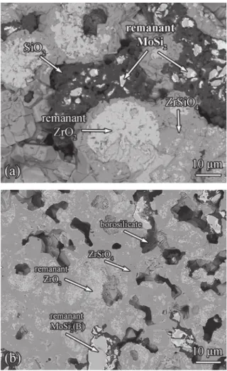
Exposure of the compacted equimolar mixtures of YPSZ pow-der with MoSi2or MoSi2(B) at high temperatures in air resulted in
the formation of silica (SiO2) or borosilicate (SiO2eB2O3) due to
oxidation of the MoSi2 particles; seeFig. 1a and b. These oxides
completely fill the space between YPSZ and the MoSi2. The
oxidation of Si originating from the MoSi2and MoSi2(B) particles
resulted in the formation of Mo5Si3; see also Refs [46e49]. The
formation of borosilicate causes a partial breakup of the SieO bonds in the silica network, which changes its properties, such as melting point, wettability and viscosity according to Refs. [17,18,50e56].
Subsequently, SiO2 reacts with t-ZrO2 of the YPSZ forming
ZrSiO4at the outer side or rim of the YPSZ particles according to:
ZrO2þ SiO2/ZrSiO4 (1)
XRD analyzes show that in addition to ZrSiO4, also Mo5Si3and
crystalline SiO2(cristobalite) were formed; seeFig. 2a. Amorphous
silica, which forms during MoSi2oxidation, tends to transform into
cristobalite prior or during reaction with ZrO2[3,46,49]. Also, some
Y2Si2O7 is observed, which suggests a reaction between the
remaining amorphous SiO2and Y2O3[57].
However, when boron is present in MoSi2, the rate of silica
formation as borosilicate is enhanced and the formation of ZrSiO4
is promoted. After annealing an equimolar mixture of YPSZ and MoSi2 with 9 at.% B at 1200!C for 15 h, only a few unreacted
MoSi2particles with Mo5Si3could be detected; seeFig. 2b. The
presence of boron led to the formation of amorphous borosilicate according to XRD analysis and EPMA; see also e.g. Refs. [9,16,52,54,55,58]. After oxidation at 1100!C some
crystal-line SiO2cristobalite was observed, but after oxidation at 1200!C
only amorphous borosilicate was formed. This suggests that the presence of B precludes the crystallization of the amorphous SiO2
to cristobalite, cf [56]. Moreover, in contrast to the oxidation reaction between the YPSZ and MoSi2particles, no Y2Si2O7 was
observed; seeFig. 2b. However, the acidic nature of the B2O3and
the high annealing temperature, B2O3can promote the removal
of yttrium ions from YPSZ [59]. This may lead to the formation of glassy YBO3 and monoclinic zirconia (m-ZrO2), but is not
observed here.
XRD analyzes of the YPSZ powder, used in the compacted powder mixtures (see Section2.1), is composed mainly of t-ZrO2
with small amount of m-ZrO2, which not changed after exposure
for at 1200!C for 15 h in air. In the XRD pattern of the YPSZ
powder used for preparing the bilayer samples with SPS (see Section2.1) only t-ZrO2and no m-ZrO2nor cubic zirconia (c-ZrO2)
was observed. Also, after SPS the compact consisted only of t-ZrO2.
After long exposure at high temperatures a minute amount of m-ZrO2 was traceable. According to the zirconia-yttria phase
dia-gram [60], in the YPSZ with 4e5 mol% Y2O3powder only m-ZrO2
and c-ZrO2are stable at room temperature. At high temperatures
(above about 550!C) the tetragonal phase is stable. However,
since the diffusion of Y ions in zirconia is slow and the driving
Fig. 1. Cross-section image of (a) YPSZ e MoSi2and (b) YPSZ e MoSi2(B) tablets after
annealing at 1200!C in laboratory air for 15 h. Corroborated with X-ray microanalysis, five main phases were identified: (1) Bright pebble like particles are remnant MoSi2
and MoSi2(B) particles, respectively. (2) The bright phase at the edge of MoSi2and
MoSi2(B) belongs to Mo5Si3. (3) The darker region represents SiO2and borosilicate,
respectively. (4) The grey region between SiO2or borosilicate and ZrO2is the reaction
product of these two components, namely ZrSiO4. (5) The whitish area is remnant
force small [27], partitioning into m-ZrO2and c- ZrO2hardly
oc-curs. This metastable phase is often referred to as tetragonal prime zirconia (t’-ZrO2).
The kinetics of the zircon formation strongly depends on the nature of the silica (i.e. amorphous or crystalline), which is related to the boron present in the MoSi2particles. The presence of boron
atoms in the SiO2lattice decreases the viscosity of glassy silica by 3
orders magnitude [18,55]. Hence, the borosilicate spreads faster over the YPSZ surface than the boron-free amorphous silica. This ensures a better coverage of these particles by borosilicate than by silica [17,51], which results in a faster consumption of ZrO2;
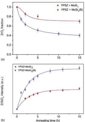
compareFig. 3a withFig. 3b.
Also, the kinetics of silica formation due to the oxidation of MoSi2is much faster when boron is present in the MoSi2particles;
see Fig. 4. The intensity of the (200) diffraction line of ZrSiO4
(having a body centered tetragonal crystal lattice) upon isothermal oxidation of the composite increases more rapidly when amor-phous instead of crystalline silica was formed. For the YPSZ and MoSi2powder mixture, ZrO2is consumed rapidly at the beginning
of the annealing process (i.e. the first hours); seeFig. 4a. A similar acceleration is observed for the YPSZ and boron containing MoSi2
powder mixture, but the amount of ZrO2 consumed and ZrSiO4
formed is twice as high; seeFig. 4a and b. Once the empty space between the particles is filled with silica, the YSPZ particles are sealed off from the oxygen in the environment. In this case, oxygen can only reach the MoSi2 particles via diffusion through the
intergranular silica. Hence, the reaction decelerates after 2 h and ceases after 5 h of isothermal annealing at 1100!C; seeFig. 4b. 3.2. Formation of silica or borosilicate and zircon in the bilayer system
Exposure of YPSZ e MoSi2bilayer system to high temperatures
in air results in similar reaction products as observed in the com-pacted powder mixtures; cf. Section3.1. A relatively thin layer of SiO2is formed in between the YPSZ and the MoSi2; seeFig. 5a. An
irregular layer of ZrSiO4is formed in the YPSZ adjacent to the SiO2
layer with some patches along YPSZ grain boundaries; seeFig. 5a. The observed bright zones in the remnant MoSi2layer correspond
to the Mo5Si3 phase (see Fig. 5a), which forms as a result of Si
depletion from the original MoSi2due to oxidation. Upon very long
exposure at 1100!C in a high oxygen partial pressure environment
further dissociation of Mo5Si3into (amorphous) SiO2will occur [3].
In the case of the YPSZ e MoSi2(B) bilayer system, an amorphous
borosilicate layer is formed in between the YPSZ and the MoSi2(B);
seeFig. 5b. Since the diffusion of oxygen through glassy borosilicate is faster than through B-free silica [56,61,62]; cf. Section 3.1, a thicker oxide layer is formed in comparison with the B-free system; seeFig. 4b. This amorphous silicate layer contains about 5 at.% B (seeFig. 6), suggesting that some of the B2O3reacts with SiO2to
form borosilicate glass [56]. In addition, occasionally a yttrium borate phase, likely YBO3[59], is observed; seeFig. 6. Also, some
B2O3 reacts with Y2O3 of the YPSZ; cf. Section 3.1. Finally, the
amorphous borosilicate reacts with the ZrO2forming ZrSiO4; see Figs. 5b and 6. In this case, a more continuous and thicker zircon layer is formed in between the borosilicate and YPSZ as compared
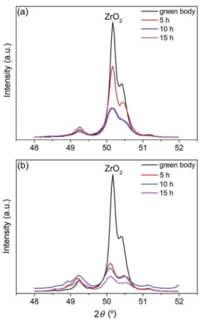
Fig. 2. X-ray diffraction patterns recorded with Cu-Karadiation of green tablets and after annealing at 1200!C for 15 h in laboratory air: (a) YPSZ e MoSi2and (b) YPSZ e MoSi2(B) composite, respectively. (For interpretation of the references to colour in this
figure legend, the reader is referred to the Web version of this article.)
Fig. 3. X-ray diffraction lines recorded with Cu-Karadiation of the (112) and (020) monoclinic and tetragonal ZrO2peaks: (a) YPSZ e MoSi2and (b) YPSZ e MoSi2(B)
composite after annealing at 1100!C in laboratory air during 5, 10 and 15 h, respectively.
with the B-free system. Moreover, it can be seen that zircon forms along the grain boundaries of YPSZ, suggesting that silicon diffuses into YPSZ; seeFig. 7.
3.3. Kinetics of silica or borosilicate formation and zircon growth in bilayer system
At the high temperatures applied in this work, the growth rate of the silica and the zircon layers is expected to be controlled by diffusion of the reacting species through the developing SiO2 or
through the ZrSiO4 layer. Then a parabolic growth rate law is
applicable in both cases. The evolution of the thickness of borosil-icate (x1) and zircon (x2) layer as a function of the oxidation time (t)
at 1100!C in air are shown inFig. 8. The initial thickness of silica
and borosilicate layers after spark plasma sintering of the bilayer couples x0is 1.0 and 2.9
mm, respectively. These closed layers may
have prevented the formation of MoO3. It can be seen that B
significantly enhances the kinetics of formation of both the silica and zircon layer.
The evolution of the borosilicate and zircon thicknesses at temperatures ranging from 1100 to 1300!C, is shown inFig. 9. As
expected, the thickness of borosilicate and zircon layer is increasing with annealing temperature and exposure time.
4. Discussion
4.1. Mechanism of silica or borosilicate and zircon formation
It has been reported that the oxidation of MoSi2is controlled by
the diffusion of oxygen ions or molecular di-oxygen through the
Fig. 4. Kinetic curves of (a) ZrO2consumption and (b) ZrSiO4formation in mixtures of
YPSZ e MoSi2(red) and YPSZ e MoSi2(B) (blue) during annealing at 1100!C in
labo-ratory air as obtained from (ex situ) XRD analysis considering the (112) and (020) ZrO2
and (200) ZrSiO4diffraction lines. Error corresponds to 3 times the standard deviation
of the number of photons counted (Poissonian distribution). (For interpretation of the references to colour in this figure legend, the reader is referred to the Web version of this article.)
Fig. 5. SEM backscattered electron images of cross-section of (a) YPSZ e MoSi2and (b)
YPSZ e MoSi2(B) interdiffusion couples after annealing for 96 h at 1100!C in laboratory
air. A silica layer (a) or borosilicate layer (b) is developed due to oxidation of MoSi2and
MoSi2(B), respectively. The very small bright phase at the edge of MoSi2and MoSi2(B)
belongs to Mo5Si3. In between the silica or borosilicate layer and the YPSZ, zircon
(ZrSiO4) is formed.
Fig. 6. Chemical composition profile across the YPSZ e MoSi2(B) interdiffusion couple
after annealing at 1200!C in laboratory air for 96 h, as obtained with EPMA. Error less than 0.5 at.% for each element.
developing continuous silica layer [3,46,63]. The oxygen transport through crystalline and amorphous silica has been studied exten-sively [61,62,64]. The oxygen diffusion in amorphous SiO2is faster
than in crystalline SiO2; seeFig. S3in Supplementary Information.
In addition, the presence of 5 at.% B in amorphous SiO2is reported
to enhance the transport of oxygen through the borosilicate glass by 4 orders of magnitude than in boron free amorphous silica.
For continued formation of amorphous SiO2, oxygen has to
diffuse through YPSZ and the developing ZrSiO4layer. The diffusion
of oxygen in t-ZrO2is several orders of magnitude faster than in
amorphous SiO2and hence is not rate limiting [62,65]; seeFig. S3in
Supplementary Information. But the diffusion of oxygen in ZrSiO4is
of the same order of magnitude as in the amorphous SiO2
[62,64,66]. Thus, for the bilayer system studied here, the oxygen diffusion either in the amorphous SiO2or in the ZrSiO4layer is the
rate controlling factor for the silica formation.
Concerning the formation of zircon, either Si or Zr cations have to diffuse through the developing ZrSiO4layer. In the first case,
zircon is formed at the ZrSiO4e YPSZ interface, while in the latter case, zircon is formed at the SiO2e ZrSiO4interface. According to
studies by Cherniak [67] and Eppler [68], Si4þis the fastest diffusing cation in ZrSiO4. Hence, diffusion of Si4þthrough the zircon layer is
thought to be the rate-limiting step of the zircon formation. This being the case, zircon would grow at the ZrSiO4- ZrO2interface.
This is consistent with a few studies which attest that zircon pre-cipitates at the ZrO2e ZrSiO4interface when the solubility limit of
silicon in ZrO2is reached [4,6]. These studies assumed that zircon
presents an over-stoichiometric silicon (ZrSi1þxO4-x) and vacancies
at the oxygen sublattice (V::
o) [6], where interstitial silicon ðSi::::i Þ are
the fastest cationic species [6,66,68e70]. Since a parabolic kinetics
Fig. 7. Phase map of YPSZ-MoSi2(B) interdiffusion couple after annealing at 1200!C in
laboratory air for 96 h, showing the ZrSiO4formation at the YPSZ e SiO2þ 5 at.% B
interface and along grain boundaries of YPSZ as obtained by SEM eEBSD of a cross section.
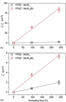
Fig. 8. Kinetics of (a) silica and borosilicate and (b) zircon layer growth in YPSZ- MoSi2
and YPSZ e MoSi2(B) interdiffusion couples when annealing at 1100!C in laboratory
air. Error bars correspond to the standard deviation of the measured thickness. The initial thickness of silica and borosilicate layers after spark plasma sintering of the bilayer couples x0is 1.0 and 2.9mm, respectively.
Fig. 9. The relation between the thickness of borosilicate (x1) and zircon (x2) layer and annealing time at different temperatures (from 1100 up to 1300!C) of the YPSZ e MoSi2(B) bilayer system. Dashed lines correspond to the linear fitting of the
experi-mental data for each temperature. Error bars correspond to the standard deviation of the measured thickness and x0equals 2.9mm, which corresponds to the initial thick-ness of silica layer formed after the spark plasma sintering of the bilayer couple.
is observed for the growth of both the silica or borosilicate and zircon layer (seeFigs. 8 and 9), the growth of these two layers is diffusion controlled rather than reaction kinetics controlled.
The ZrSiO4forms at the ZrO2- ZrSiO4interface according to the
following reaction:
Si4þþ 2 O2#þ ZrO2/ ZrSiO4 (2)
For this reaction to proceed both O2#and Si4þions must arrive at this interface. The oxygen ions originating from the gaseous environment can readily diffuse inward through the YPSZ layer [71]. The Si4þ ions coming from the silica or borosilicate layer diffuse through the ZrSiO4 layer, likely as an interstitial [67]. This
implies dissociation of SiO2at the SiO2eZrSiO4interface into Si4þ
and O2#ions. Since the oxygen potential at the SiO2eZrSiO4
inter-face is higher than at the MoSi2eSiO2interface, the oxygen ions
diffuse through the silica layer towards the MoSi2eSiO2interface
and react with MoSi2contributing to the growth of the silica or the
borosilicate layer. Thus, the growth kinetics of the silica or the borosilicate layer also depends on the diffusion of the Si4þions through the zircon layer.
4.2. Kinetic model for silica or borosilicate formation and zircon growth in bilayer system
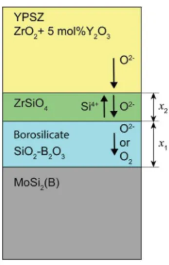
The following model, schematically represented inFig. 10, is proposed to explain the growth kinetics of the silica or borosilicate and zircon layer in the YPSZ e MoSi2(with and without B) bilayer
system. The advantage of this model is that it allows the assessment of the mechanisms that control the formation of the silica or the borosilicate and the growth of the zircon layer.
Two cases need to be considered. In the first case, diffusion of oxygen in the silica or borosilicate layer is the rate determining step for the silica and borosilicate formation, and the diffusion of silicon in the developing zircon layer is the rate determining step for the zircon formation. In the second case, diffusion of oxygen in zircon is controlling the growth of silica and the diffusion of silicon in zircon is controlling the growth rate of the zircon layer.
4.2.1. Oxygen diffusion in silica or borosilicate being the rate-limiting step for silica growth
At temperatures above 1100!C, oxidation of a bare MoSi2
sub-strate is known to be controlled by the slow diffusion of oxygen
through the silica layer [46,72]. Then, for the growth or production (p) of silica or borosilicate it can be written:
dx1 dt ! ! ! ! p¼ k1 2x1 (3)
where x1is the thickness of the silica layer, t is the oxidation time
and k1 the parabolic rate constant related to oxygen diffusion.
Similarly, for the formation of zircon it can be written:
dx2
dt ¼ k2
2x2
(4)
where x2is the thickness of the zircon layer and k2the parabolic
rate constant related to silicon diffusion in zircon. Since no zircon is present in the bilayer systems prior to annealing at high temper-atures in air, i.e. x2¼ 0 at t ¼ 0, integration of Eq.(4)yields: x2¼
ffiffiffiffiffiffiffiffiffiffi k2,t p
(5)
However, for the formation of zircon, part of the silica is consumed. The rate of this consumption (c) is proportional to the zircon formation rate described by the parabolic rate constant k2, cf.
Eqs(4) and (5). The net (S) thickening kinetics of the silica or bo-rosilicate layer is obtained using Eqs(3) and (4), hence:
dx1 dt ! ! ! !S¼ dx1 dt ! ! ! !p# dx1 dt ! ! ! !c¼ k1 2x1# k2 2x2, VSiO2 VZrSiO4 (6)
in which VSiO2 and VZrSiO4are the molar volumes of silica or
boro-silicate and zircon, respectively. For the molar volume of silica or borosilicate, the value of amorphous silica is taken and equals 29 cm3mol#1[2]. The molar volume of zircon is 40 cm3mol#1[73]. The physically consistent solution of Eq.(6)is given by:
x1¼
ffiffiffiffiffiffiffiffiffiffiffiffiffi kapp,t q
(7)
where kappis the apparent parabolic rate constant. This parabolic
rate constant is related to the overall mechanism involved in silica formation, i.e. production and consumption of silica. The rate constant k1is directly related to the oxygen diffusion through the
silica or borosilicate layer when it grows on the MoSi2(B) itself.
Combining Eqs(5)e(7), results in:
dx1 dt ! ! ! !S¼ k1 2 ffiffiffiffiffiffiffiffiffiffiffiffiffi kapp,t p #
a
, ffiffiffiffiffi k2 p 2 ffiffi t p ¼ kffiffiffiffiffiffiffiffiffi1 kapp p #a
, ffiffiffiffiffi k2 p ! , ' 1 2 ffiffi t p ( (8)where
a
equals VSiO2=VZrSiO4. This equation can be solvedconsid-ering that in our experiments the thickness of the initial silica or borosilicate layer (x0) is small in comparison to the thickness upon
prolonged oxidation (x1), i.e. x0z0 at t¼ 0 (cf.Figs. 8a and 9a); hence: x1¼ k1 ffiffiffiffiffiffiffiffiffi kapp p #
a
, ffiffiffiffiffi k2 p ! ,pffiffit (9)According to Eq.(9)the growth of silica in between MoSi2(with
and without B) and ZrSiO4is described with a parabolic function, a
prediction which agrees well with our experimental observations; seeFigs. 8a and 9a. This implies that the proposed solution of Eq.
(6), i.e. Eq.(7)is valid. When identifying the terms of Eqs(7) and (9), one obtains:
Fig. 10. Schematic of the transport phenomena associated with the formation of bo-rosilicate and ZrSiO4 layers in the YPSZ e MoSi2(B) interdiffusion couples when
ffiffiffiffiffiffiffiffiffi kapp q ¼ kffiffiffiffiffiffiffiffiffi1 kapp p #
a
, ffiffiffiffiffi k2 p (10)Now, the apparent parabolic rate constant can be expressed explicitly in terms of k1and k2:
kapp¼1 2, )
a
2,k2þ 2k1#a
, ffiffiffiffiffiffiffiffiffiffiffiffiffiffiffiffiffiffiffiffiffiffiffiffiffiffiffiffiffiffiffiffiffiffiffik2*a
2 ,k2þ 4k1+ q , (11)The parabolic rate constant k1 can be calculated from the
parabolic rate constants determined from the silica or borosilicate formation (kapp) and the zircon formation (k2) in the bilayer
sys-tems; seeFigs. 7e9, respectively. The relationship between these constants reads: k1¼ kappþ
a
, ffiffiffiffiffiffiffiffiffiffiffiffiffiffiffiffi k2,kapp q (12)4.2.2. Oxygen diffusion in zircon being the rate-limiting step for silica growth
If the diffusion of oxygen in the developing zircon layer is slower than in the silica or borosilicate layer, the growth of the latter will be determined by the rate of oxygen diffusion in zircon. Analogous to Eq.(6), for the net growth of the silica or borosilicate it can be written: dx1 dt ! ! ! ! S ¼ 2xk3 2# k2 2x2 , VSiO2 VZrO4 (13)
but now, with k2and k3as the parabolic rate constant pertaining to
silicon diffusion and oxygen diffusion in zircon, respectively. A so-lution of Eq.(13)is obtained by considering that in our experiments the thickness of the initial silica or borosilicate layer (x0) is small
compared with the thickness upon prolonged oxidation (x1), i.e. x0z0 at t¼ 0 (cf. Eq.(9), hence: x1¼ k3#
a
, ffiffiffiffiffi k2 p ffiffiffiffiffi k2 p ! ,pffiffit (14)Adopting Eq.(9), the apparent parabolic rate constant for the net growth of silica or borosilicate layer in the bilayer systems can be obtained: ffiffiffiffiffiffiffiffiffi kapp q ¼ kffiffiffiffiffiffiffiffiffi3 kapp p #
a
, ffiffiffiffiffi k2 p (15)The relation between the parabolic rate constant k3and the ones
determined from the observed silica or borosilicate formation (kapp)
and zircon formation (k2) reads: k3¼
a
,k2þffiffiffiffiffiffiffiffiffiffiffiffiffiffiffiffi k2,kapp
q
(16)
4.3. Analysis of observed silica or borosilicate and zircon growth kinetics in bilayer system
The observed kinetics of both silica or borosilicate and zircon formation in the YPSZeMoSi2and the YPSZeMoSi2(B) bilayer
sys-tems (presented inFigs. 8 and 9), is evaluated and quantified with the kinetic model presented in Section4.2. The apparent parabolic growth rate constant, kapp(cf. Eq.(7)), can be obtained directly from
the measured silica layer thicknesses versus annealing time of the YPSZ e MoSi2(with or without B) bilayer system; seeFig. 8a. The
presence of an initial silica layer (i.e. x0the thickness at time t0) has
to be taken into account, since a thin layer forms during the spark plasma sintering process of the bilayer system. Then, the kapp
equation reads as:
x21# x20¼ kapp,ðt # t0Þ (17)
The parabolic rate constant k2, cf. Eq.(5), is determined from the
measured zircon layer thicknesses versus the annealing time; see
Fig. 9b. The results for YPSZ e MoSi2without boron bilayer system
annealed in air at 1100!C are presented inTable 1. In addition, the
parabolic rate constants pertaining to either oxygen diffusion in silica (k1) or oxygen diffusion in zircon (k3), which determines the
growth of silica in the YPSeMoSi2 boron free system (cf. Section 3.2) are evaluated using Eqs(12) and (16), respectively; seeTable 1. The obtained results indicate that the ZrSiO4layer developed is too
thin and not continuous (seeFig. 5a) and hence, its presence has a minor effect in controlling the further oxidation of the remaining MoSi2; seeTable 1. Furthermore, the value of the parabolic constant k1for the YPSZeMoSi2bilayer system is in close agreement with
the parabolic rate constant determined for the oxidation of MoSi2
bulk in air at 1100!C (i.e. 1.1,10#14cm2s#1) [3,74]. Thus, our results
suggest that for the system without boron the growth rate of silica is controlled by oxygen diffusion in silica.
For the YPSZ e MoSi2(B) bilayer system, the addition of 9 at.% of
B leads to an increase of both the rate of borosilicate and that of zircon formation. The parabolic rate constants, kappand k2, increase
by factor of 35 and 4, respectively, due to the presence of B in MoSi2.
Clearly the diffusion of oxygen through borosilicate and zircon layer is enhanced by alloying MoSi2 with boron; see Section 3.2. The
former is due to the presence of B in the SiO2network, which alters
the characteristics of silica glass [17]. Once B dissolves into silica, large [B5O6]3-ring segments develop inside the SiO2network and
widen the [SiO4]4-tetrahedra [75], which accelerates the oxygen
transport through the borosilicate layer. The latter is due to the more loose network in the borosilicate [17,51,61].
At 1100!C, when boron is present in MoSi2, kappand k1increase
by a factor of 35 and 23.5, respectively, while k3value only increases
by a factor of 8.6. This suggests that diffusion of oxygen through the amorphous SiO2layer controls the growth of the borosilicate scale.
In addition, the values of k1are by factor of 1.2 larger than of kapp,
for temperatures ranging from 1100 to 1300!C, suggesting that the
silica consumption to form zircon has only a small effect on the growth kinetics of silica. This holds irrespective of the presence of boron.
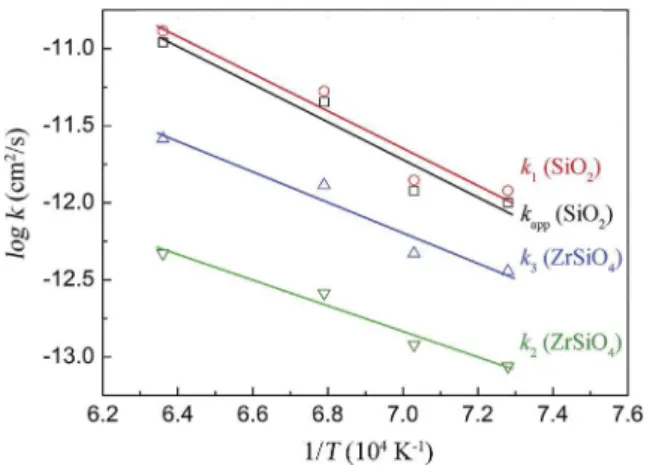
Since the diffusion of species at high temperatures in the bilayer systems is a thermally activated process, the temperature depen-dence of the parabolic rate constant can be described with an Arrhenius type equation:
k ¼ A expð # EA=RTÞ (18)
where A is the pre-exponential factor, which is assumed to be temperature independent, R is the gas constant, T is the tempera-ture and EAis the activation energy. This holds for k1, k2and k3,
which are related to the diffusion of single species. However, kapp
may not follow the Arrhenius law (Eq.(18)) since it combines the effect of diffusion of two species. Nevertheless, as can be seen in
Fig. 11the kappvalues do not differ much from the k1values, an
apparent activation energy can be evaluated from the kappvalues.
The activation energies and pre-exponential factor were deter-mined from the parabolic growth constants obtained for the YPSZeMoSi2(B) bilayer system (seeFig. 11andTable 1), and the
results are summarized inTable 2. For the borosilicate formation dominated by oxygen diffusion in the silicate, an activation energy
of 234 ± 44 kJ mol#1 and a pre-exponential factor of
1.9$10#8cm2s#1are obtained. The value of the activation energy determined here is lower than those reported in the literature for the oxidation of bulk MoSi2(i.e. 300 ÷ 340 kJ mol#1) [46,76,77]. This
is attributed to the structural characteristics of the borosilicate glass (i.e. the increased degree of [SiO4]4-deformation due to
sol-ubility of B in the SiO2network; also see Section3.2and Ref. [75]. As
a result, the oxygen diffusion through the borosilicate layer is enhanced and therefore, a lower activation energy is attained for the YPSZeMoSi2(B). The activation energy for the oxidation of
isolated MoSi2 particles containing 9 at.% B is even found to be
about 2 times lower than the value obtained in this study (i.e. about 107 kJ mol#1determined for temperatures ranging between 1050
and 1200!C).
An activation energy of 159 ± 23 kJ mol#1and a pre-exponential factor of 9.1$10#8cm2s#1are obtained for zircon formation. Since k2is proportional to the silicon diffusion coefficient in zircon, the
activation energy obtained from Eq.(18) can be compared with values reported in the literature and calculated from the self-diffusion coefficients of silicon in zircon. The activation energy for Si diffusion in zircon for MoSi2with 9 at.% B e YPSZ systems is
nearly 4.5 and 3.5 times lower than those obtained by Cherniak [67] and Zhang and Wu [66], while the activation energy calculated by Veytizou et al. [6] is 2 times higher than the one obtained in this study. The authors determined the rates of zircon formation via solid-state reaction of amorphous silica and tetragonal zirconia [6]. It is worth noting that both studies (i.e. Veytizou et al. [6] and Cherniak [67]) do not incorporate the effect of boron on the network of amorphous silica, nor on the kinetics of zircon forma-tion. As documented, once B dissolves into silica network, it partially breaks the Si e O bond, leading to a weaker network than that of B free amorphous silica [17,51]. This likely makes the transport of Sii···· interstitials easier and, hence explain the lower
activation energy value for silicon diffusion in zircon for the YPSZ e MoSi2(B) bilayer system.
5. Conclusions
The formation mechanism and kinetics of both borosilicate and zircon in YPSZ e MoSi2 (without B and with 9 at.% B) powder
mixtures and bilayer systems were investigated. It is demonstrated that:
1. Zircon can be formed below 1200!C in the YPSZ e MoSi2
powder mixture or from the bilayer, irrespective of the prior presence of B in the MoSi2.
2. The presence of 9 at.% B in MoSi2prevents the crystallization of
the amorphous SiO2 formed and facilitates the formation of
ZrSiO4, accelerating the reaction rate by factor of two (for the
powder mixture) or four (for the bilayer).
3. The kinetics of the zircon formation as determined by annealing of the YPSZ/MoSi2bi-layered systems obeys a parabolic growth
rate law. This is consistent with the diffusion of Si4þ(likely Sii····)
through the zircon layer being the growth rate depending step, rather than an (hypothetical) interfacial reaction (i.e. SiO2
dissolution at SiO2 - ZrSiO4 interface or ZrSiO4 formation at
ZrSiO4/YPSZ interface).
4. The growth of the SiO2or SiO2 e 5 at.% B oxide scales below ZrSiO4layer obeys a parabolic law. The kinetic model suggests
that the diffusion of oxygen through the silica or borosilicate layer dominates the growth of the borosilicate scale.
5. The presence of B in MoSi2significantly increases the zircon and
silica formation rates. At 1100!C the parabolic rate constant for
zircon formation increases by a factor of 4 when boron is present and the rate of silica formation by a factor of 35. The increase in both formation rates will accelerate the crack healing in YPSZ with embedded B-containing MoSi2particles.
The kinetic data as obtained in this work are crucial for quan-titative modelling of the healing kinetics and the lifetime extension for extrinsic self-healing YPSZ thermal barrier coatings containing healing particles of the compositions studied here.
Table 1
Parabolic rate constants kapp, k1, k2and k3related to the growth of borosilicate and zircon layers in the YSZ e MoSi2and YSZ e MoSi2(B) interdiffusion systems.
Temperature (!C) 1100 1150 1200 1300
YPSZ/MoSi2 SiO2 kapp(cm2s#1) 2.9$10#14 e e e
k1(cm2s#1)a 5.1$10#14 e e e
ZrSiO4 k2(cm2s#1) 2.3$10#14
k3(cm2s#1)a 4.2$10#14 e e e
YPSZ/MoSi2-9 at.%B SiO2with 5 at.%B kapp(cm2s#1) 1.0$10#12 1.2$10#12 4.5$10#12 1.1$10#11 k1(cm2s#1)a 1.2$10#12 1.4$10#12 5.3$10#12 1.3$10#11
ZrSiO4 k2(cm2s#1) 8.7$10#14 1.2$10#13 2.6$10#13 4.7$10#13
k3(cm2s#1)a 3.6$10#13 4.7$10#13 1.3$10#12 2.6$10#12 aCalculated using Eqs.(12) and (16).
Fig. 11. Arrhenius plots of the rate constants k1,kapp,k2and k3for the YSZ-MoSi2(B)
interdiffusion couples. The activation energies and pre-exponential factors are ob-tained from linear fitting to the data points.
Table 2
Activation energy EAand pre-exponential factor A of the thermally activated growth of the borosilicate and zircon layers in the YSZ e MoSi2(B) interdiffusion couple
given by the parabolic rate constants kapp, k1, k2and k3; cf. Eq.(18).
Layer A (cm2/s) E
A(kJ/mol) Net borosilicate growth (kapp) 1.9$10#8 #228 ± 42 Borosilicate growth (k1) 1.9$10#8 #234 ± 44
Zircon growth by oxygen diffusion (k2) 9.8$10#8 #159 ± 23
Acknowledgments
This project has received funding from European Union Seventh Framework Program (FP7/2007e2013) under grant agreement no. 309849, SAMBA. The authors thank Ing. R. W. A. Hendrikx for the XRD analysis.
Appendix A. Supplementary data
Supplementary data to this article can be found online at
https://doi.org/10.1016/j.actamat.2019.05.046. References
[1]W.G. Sloof, S.R. Turteltaub, A.L. Carabat, Z. Derelioglu, P. S.A, G.M. Song, Crack healing in yttria stabilized zirconia thermal barrier coatings, in: S. van der Zwaag, E. Brinkman (Eds.), Self Healing Materials: Pioneering Research in the Netherlands, IOS Press, Amsterdam, 2015, pp. 217e225.
[2]Z. Derelioglu, A.L. Carabat, G.M. Song, S. van der Zwaag, W.G. Sloof, On the use of B-alloyed MoSi2particles as crack healing agents in yttria stabilized zirconia thermal barrier coatings, J. Eur. Ceram. Soc. 35 (16) (2015) 4507e4511. [3]S. Knittel, S. Mathieu, M. Vilasi, The oxidation behaviour of uniaxial hot
pressed MoSi2in air from 400 to 1400 degrees C, Intermetallics 19 (8) (2011) 1207e1215.
[4]T. Itoh, formation of polycrystalline zircon (ZrSiO4) from amorphous silica and amorphous zirconia, J. Cryst. Growth 125 (1e2) (1992) 223e228.
[5]T. Mori, H. Yamamura, H. Kobayashi, T. Mitamura, formation mechanism of ZrSiO4powders, J. Mater. Sci. 28 (18) (1993) 4970e4973.
[6]C. Veytizou, J.F. Quinson, O. Valfort, G. Thomas, Zircon formation from amorphous silica and tetragonal zirconia: kinetic study and modelling, Solid State Ionics 139 (3e4) (2001) 315e323.
[7]M. Meyer, M. Kramer, M. Akinc, Boron-doped molybdenum silicides, Adv. Mater. 8 (1) (1996) 85e88.
[8]M.K. Meyer, M. Akinc, Isothermal oxidation behavior of Mo-Si-B intermetallics at 1450!C, J. Am. Ceram. Soc. 79 (10) (1996) 2763e2766.
[9]M.K. Meyer, M. Akinc, Oxidation behavior of boron-modified Mo5Si3at 800-1300!C, J. Am. Ceram. Soc. 79 (4) (1996) 938e944.
[10] M. Akinc, M.K. Meyer, M.J. Kramer, A.J. Thom, J.J. Huebsch, B. Cook, Boron-doped molybdenum silicides for structural applications, Mater. Sci. Eng. A 261 (1e2) (1999) 16e23.
[11] Z. Tang, A.J. Thom, M.J. Kramer, M. Akinc, Characterization and oxidation behavior of silicide coating on multiphase Mo-Si-B alloy, Intermetallics 16 (9) (2008) 1125e1133.
[12] P.R. Taleghani, S. Bakhshi, M. Erfanmanesh, G. Borhani, R. Vafaei, Improve-ment of MoSi2Oxidation Resistance via Boron Addition: Fabrication of MoB/ MoSi2Composite by Mechanical Alloying and Subsequent Reactive Sintering, 2014.
[13] P. Mandal, A.J. Thom, M.J. Kramer, V. Behrani, M. Akinc, Oxidation behavior of Mo-Si-B alloys in wet air, Mater. Sci. Eng. A 371 (1e2) (2004) 335e342. [14] C.G. McKamey, P.F. Tortorelli, J.H. DeVan, C.A. Carmichael, A study of pest
oxidation in polycrystalline MoSi2, J. Mater. Res. 7 (10) (1992) 2747e2755.
[15] T.C. Chou, T.G. Nieh, Mechanism of MoSi2 pest during low temperature oxidation, J. Mater. Res. 8 (1) (1993) 214e226.
[16] A.J. Thom, E. Summers, M. Akinc, Oxidation behavior of extruded Mo5Si3Bx -MoSi2-MoB intermetallics from 600-1600!C, Intermetallics 10 (6) (2002) 555e570.
[17] F. Monteverde, A. Bellosi, Oxidation of ZrB2-based ceramics in dry air, J. Electrochem. Soc. 150 (11) (2003) B552eB559.
[18] T. Karahan, G. Ouyang, P.K. Ray, M.J. Kramer, M. Akinc, Oxidation mechanism of W substituted Mo-Si-B alloys, Intermetallics 87 (2017) 38e44.
[19] K. Kochubey, W.G. Sloof, Self Healing Mechanism in Thermal Barrier Coatings, ITSC 2008, DVS-Verlag GmbH, Maastricht, The Netherlands, 2008.
[20] D. Koch, G. Mauer, R. Vaßen, Manufacturing of composite coatings by atmo-spheric plasma spraying using different feed-stock materials as YSZ and MoSi2, J. Therm. Spray Technol. 26 (4) (2017) 708e716.
[21] F. Nozahic, C. Estournes, A.L. Carabat, W.G. Sloof, S. van der Zwaag, D. Monceau, Self-healing thermal barrier coating systems fabricated by spark plasma sintering, Mater. Des. 143 (2018) 204e213.
[22] Y. Chen, X. Zhang, S. van der Zwaag, W.G. Sloof, P. Xiao, Damage evolution in a healing air plasma sprayed thermal barrier coating containing self-shielding MoSi2particles, J. Am. Ceram. Soc. (2019),https://doi.org/10.1111/
jace.16313in press.
[23] N.P. Padture, M. Gell, E.H. Jordan, Thermal barrier coatings for gas-turbine engine applications, Science 296 (5566) (2002) 280e284.
[24] D.R. Clarke, S.R. Phillpot, Thermal barrier coating materials, Mater. Today 8 (6) (2005) 22e29.
[25] M. Belmonte, Advanced ceramic materials for high temperature applications, Adv. Eng. Mater. 8 (8) (2006) 693e703.
[26] F. Cernuschi, P. Bison, A. Moscatelli, Microstructural characterization of porous thermal barrier coatings by laserflash technique, Acta Mater. 57 (12) (2009)
3460e3471.
[27] D.R. Clarke, C.G. Levi, Materials design for the next generation thermal barrier coatings, Annu. Rev. Mater. Res. 33 (1) (2003) 383e417.
[28] R.T. Wu, K. Kawagishi, H. Harada, R.C. Reed, The retention of thermal barrier coating systems on single-crystal superalloys: effects of substrate composi-tion, Acta Mater. 56 (14) (2008) 3622e3629.
[29] X. Zhang, J. Kulczyk-Malecka, J. Carr, P. Xiao, P.J. Withers, 3D characterization of porosity in an air plasma-sprayed thermal barrier coating and its effect on thermal conductivity, J. Am. Ceram. Soc. 101 (6) (2018) 2482e2492. [30] J.T. DeMasi-Marcin, D.K. Gupta, Protective coatings in the gas turbine engine,
Surf. Coating. Technol. 68 (1994) 1e9.
[31] M.A. Alvin, K. Klotz, B. McMordie, D. Zhu, B. Gleeson, B. Warnes, Extreme temperature coatings for future gas turbine engines, J. Eng. Gas Turbines Power 136 (11) (2014).
[32] E.P. Busso, J. Lin, S. Sakurai, A mechanistic study of oxidation-induced degradation in a plasma-sprayed thermal barrier coating system.: Part II: life prediction model, Acta Mater. 49 (9) (2001) 1529e1536.
[33] C. Li, X. Zhang, Y. Chen, J. Carr, S. Jacques, J. Behnsen, M. di Michiel, P. Xiao, R. Cernik, Understanding the residual stress distribution through the thick-ness of atmosphere plasma sprayed (APS) thermal barrier coatings (TBCs) by high energy synchrotron XRD; digital image correlation (DIC) and image based modelling, Acta Mater. 132 (2017) 1e12.
[34] M. Mutter, G. Mauer, R. Mücke, O. Guillon, R. Vaßen, Systematic investigation on the influence of spray parameters on the mechanical properties of atmo-spheric plasma-sprayed YSZ coatings, J. Therm. Spray Technol. 27 (4) (2018) 566e580.
[35] J. Kulczyk-Malecka, X. Zhang, J. Carr, F. Nozahic, C. Estourn"es, D. Monceau, A.L. Carabat, W.G. Sloof, S. van der Zwaag, P.J. Withers, P. Xiao, Thermo e mechanical properties of SPS produced self-healing thermal barrier coatings containing pure and alloyed MoSi2particles, J. Eur. Ceram. Soc. 38 (12) (2018) 4268e4275.
[36] A. Rabiei, A.G. Evans, Failure mechanisms associated with the thermally grown oxide in plasma-sprayed thermal barrier coatings, Acta Mater. 48 (15) (2000) 3963e3976.
[37] A.G. Evans, D.R. Mumm, J.W. Hutchinson, G.H. Meier, F.S. Pettit, Mechanisms controlling the durability of thermal barrier coatings, Prog. Mater. Sci. 46 (5) (2001) 505e553.
[38] K.W. Schlichting, N.P. Padture, E.H. Jordan, M. Gell, Failure modes in plasmsprayed thermal barrier coatings, Materials Science and Engineering a-Structural Materials Properties Microstructure and Processing 342 (1e2) (2003) 120e130.
[39] X. Chen, J.W. Hutchinson, M.Y. He, A.G. Evans, On the propagation and coa-lescence of delamination cracks in compressed coatings: with application to thermal barrier systems, Acta Mater. 51 (7) (2003) 2017e2030.
[40] L.B. Chen, Yttria-stabilized zirconia thermal barrier coatings - a review, Surf. Rev. Lett. 13 (5) (2006) 535e544.
[41] H. Echsler, V. Shemet, M. Schutze, L. Singheiser, W.J. Quadakkers, Cracking in and around the thermally grown oxide in thermal barrier coatings: a com-parison of isothermal and cyclic oxidation, J. Mater. Sci. 41 (4) (2006) 1047e1058.
[42] D. Liu, M. Seraffon, P.E.J. Flewitt, N.J. Simms, J.R. Nicholls, D.S. Rickerby, Effect of substrate curvature on residual stresses and failure modes of an air plasma sprayed thermal barrier coating system, J. Eur. Ceram. Soc. 33 (15e16) (2013) 3345e3357.
[43] M.D. Hager, P. Greil, C. Leyens, S. van der Zwaag, U.S. Schubert, Self-healing materials, Adv. Mater. 22 (47) (2010) 5424e5430.
[44] F. Nozahic, D. Monceau, C. Estournes, Thermal cycling and reactivity of a MoSi2/ZrO2 composite designed for self-healing thermal barrier coatings, Mater. Des. 94 (2016) 444e448.
[45] J.T. Armstrong, Quantitative elemental analysis of individual microparticles with electron beam instruments, in: K.F.J. Heinrich, D.E. Newbury (Eds.), Electron Probe Quantitation, Springer US, Boston, MA, 1991, pp. 261e315. [46] C.D. Wirkus, D.R. Wilder, High-temperature oxidation of molybdenum
dis-ilicide, J. Am. Ceram. Soc. 49 (4) (1966) 173e&.
[47] Y.T. Zhu, M. Stan, S.D. Conzone, D.P. Butt, Thermal oxidation kinetics of MoSi2-based powders, J. Am. Ceram. Soc. 82 (10) (1999) 2785e2790.
[48] Y.T. Zhu, L. Shu, D.P. Butt, Kinetics and products of molybdenum disilicide powder oxidation, J. Am. Ceram. Soc. 85 (2) (2002) 507e509.
[49] S. Lohfeld, M. Schütze, Oxidation behaviour of particle reinforced MoSi2 composites at temperatures up to 1700!C. Part I: literature review, Mater. Corros. 56 (2) (2005) 93e97.
[50] E.F. Riebling, Structure of borosilicate and borogermanate melts at 1300!C; a viscosity and density study, J. Am. Ceram. Soc. 47 (10) (1964) 478e483. [51] F. Monteverde, A. Bellosi, The resistance to oxidation of an HfB2eSiC
com-posite, J. Eur. Ceram. Soc. 25 (7) (2005) 1025e1031.
[52] R. Sakidja, J.S. Park, J. Hamann, J.H. Perepezko, Synthesis of oxidation resistant silicide coatings on Mo-Si-B alloys, Scripta Mater. 53 (6) (2005) 723e728. [53] R. Sakidja, J.H. Perepezko, S. Kim, N. Sekido, Phase stability and structural
defects in high-temperature Mo-Si-B alloys, Acta Mater. 56 (18) (2008) 5223e5244.
[54] F.A. Rioult, S.D. Imhoff, R. Sakidja, J.H. Perepezko, Transient oxidation of Mo-Si-B alloys: effect of the microstructure size scale, Acta Mater. 57 (15) (2009) 4600e4613.
[55] J.A. Lemberg, R.O. Ritchie, Mo-Si-B alloys for ultrahigh-temperature structural applications, Adv. Mater. 24 (26) (2012) 3445e3480.
[56] D. Li, Z. Yang, D. Jia, X. Duan, S. Wang, Q. Zhu, Y. Miao, J. Rao, Y. Zhou, Effects of boron addition on the high temperature oxidation resistance of dense sSiBCN monoliths at 1500!C, Corros. Sci. 126 (2017) 10e25.
[57] D.M. Cupid, H.J. Seifert, Thermodynamic calculations and phase stabilities in the Y-Si-C-O system, J. Phase Equilibria Diffusion 28 (1) (2007) 90e100. [58] G. Ouyang, P.K. Ray, S. Thimmaiah, M.J. Kramer, M. Akinc, P. Ritt,
J.H. Perepezko, Oxidation resistance of a Mo-W-Si-B alloy at 1000e1300!C: the effect of a multicomponent Mo-Si-B coating, Appl. Surf. Sci. 470 (2019) 289e295.
[59] D.Z. de Florio, R. Muccillo, Effect of boron oxide on the cubic-to-monoclinic phase transition in yttria-stabilized zirconia, Mater. Res. Bull. 39 (10) (2004) 1539e1548.
[60] H.G. Scott, Phase relationships in the zirconia-yttria system, J. Mater. Sci. 10 (1975) 1527e1535.
[61] J. Schlichting, Glasses and Glass Ceramics from Gels Oxygen transport through glass layers formed by a gel process, J. Non-Cryst. Solids 63 (1) (1984) 173e181.
[62] M.A. Lamkin, F.L. Riley, R.J. Fordham, Oxygen mobility in silicon dioxide and silicate glasses: a review, J. Eur. Ceram. Soc. 10 (5) (1992) 347e367. [63] Y.Q. Liu, G. Shao, P. Tsakiropoulos, On the oxidation behaviour of MoSi2,
In-termetallics 9 (2) (2001) 125e136.
[64] E.B. Watson, D.J. Cherniak, Oxygen diffusion in zircon, Earth Planet. Sci. Lett. 148 (3e4) (1997) 527e544.
[65] M.S. Khan, M.S. Islam, D.R. Bates, Cation doping and oxygen diffusion in zir-conia: a combined atomistic simulation and molecular dynamics study, J. Mater. Chem. 8 (10) (1998) 2299e2307.
[66] B.H. Zhang, X.P. Wu, Prediction of self-diffusion and heterodiffusion co-efficients in zircon, J. Asian Earth Sci. 42 (1e2) (2011) 134e141.
[67] D.J. Cherniak, Si diffusion in zircon, Phys. Chem. Miner. 35 (4) (2008) 179e187.
[68] R.A. Eppler, Mechanism of formation of zircon stains, J. Am. Ceram. Soc. 53 (8) (1970) 457e&.
[69] K.M. Trappen, R.A. Eppler, Reaction of zirconia with silica at the stoichiometry of zircon, J. Am. Ceram. Soc. 72 (6) (1989) 882e885.
[70] A. Kaiser, M. Lobert, R. Telle, Thermal stability of zircon (ZrSiO4), J. Eur. Ceram. Soc. 28 (11) (2008) 2199e2211.
[71] M. Kilo, C. Argirusis, G. Borchardt, R.A. Jackson, Oxygen diffusion in yttria stabilised zirconia - experimental results and molecular dynamics calcula-tions, Phys. Chem. Chem. Phys. 5 (11) (2003) 2219e2224.
[72] J.S. Park, R. Sakidja, J.H. Perepezko, Coating designs for oxidation control of Mo-Si-B alloys, Scripta Mater. 46 (11) (2002) 765e770.
[73] P.C. P, K. Villars, Pearson's crystal data: crystal structure database for inorganic compounds, ASM International 9 (2008).
[74] S. Melsheimer, M. Fietzek, V. Kolarik, A. Rahmel, M. Schutze, Oxidation of the intermetallics MoSi2and TiSi2- a comparison, Oxid. Metals 47 (1e2) (1997) 139e203.
[75] J. Schlichting, Oxygen transport through silica surface layers on sili con-taining ceramic materials, High. Temp. - High. Press. 14 (6) (1982) 717e724. [76] E.W. Sucov, Diffusion of oxygen in vitreous silica, J. Am. Ceram. Soc. 46 (1)
(1963) 14e20.
[77] A.A. Sharif, High-temperature oxidation of MoSi2, J. Mater. Sci. 45 (4) (2010) 865e870.