O
pen
A
rchive
T
OULOUSE
A
rchive
O
uverte (
OATAO
)
OATAO is an open access repository that collects the work of Toulouse researchers and
makes it freely available over the web where possible.
This is an author-deposited version published in:
http://oatao.univ-toulouse.fr/
Eprints ID : 14533
To link to this article : DOI :
10.1108/AEAT-06-2014-0087
URL :
http://dx.doi.org/10.1108/AEAT-06-2014-0087
To cite this version:
Chinwicharnam, Kwanchai and Gomez Ariza,
David and Moschetta, Jean-Marc and Thipyopas, Chinnapat
A
computation study on the aerodynamic influence of interaction
wing-propeller for a tilt-body MAV.
Aircraft Engineering and Aerospace Technology: An International
Journal, vol.87 (n°6). pp.521-529. ISSN 0002-2667
Any correspondance concerning this service should be sent to the repository
influence of interaction wing-propeller for a
tilt-body MAV
Kwanchai Chinwicharnam
Faculty of Engineering, Kasetsart University, Bangkok, Thailand
Edgard David Gomez Ariza and Jean-Marc Moschetta
Institut Supérieur de l’Aéronautique et de l’Espace, Toulouse, France, and
Chinnapat Thipyopas
Faculty of Engineering, Kasetsart University, Bangkok, Thailand
AbstractPurpose – The purpose of this paper is to investigate the influence of a propeller slipstream on the aerodynamic characteristics of a fixed-wing micro
air vehicle (MAV) by simplifying a propeller to an actuator disk and an actuator volume.
Design/methodology/approach – A computational fluid dynamic (CFD) approach.
Findings – The simulation flows are found and show that the propeller slipstream changes the flow field around the wing, which improves the
aerodynamic performance of the wing. The aerodynamic performance is improved first, when the separation of the boundary flow at the upper surface wing is delayed. Second, the flow region of the boundary layer is boosted close to the wing surface again at a high incidence angle. And finally, the velocity inlet of the wing is increased by the propeller-induced flow.
Research limitations/implications – The incidence angle is in the range of 0-80°with an increment of 20°. The free stream velocity and RPM used
are 6 m/s and 5,000 rpm, respectively.
Originality/value – A propeller is simplified to an actuator disk and an actuator volume.
Keywords Actuator disk, Actuator volume, Interaction wing-propeller, Low aspect ratio wing, Tail-sitter, MAV, CFD, Tilt-body Paper type Technical paper
Nomenclature
Symbols
CD ⫽ Drag coefficient
CL ⫽ Lift coefficient
T ⫽ Thrust (m)
S ⫽ Propeller disk area (m2
) r ⫽ Radial position (m) R ⫽ Propeller radius (m) Va ⫽ Axial velocity (m/s) Vr ⫽ Radial velocity (m/s) Vt ⫽ Tangential velocity (m/s) ⌬P ⫽ Pressure jump (N/m)
␣ ⫽ Angle of attack (Deg)
Definitions, acronyms and abbreviations
AD ⫽ Actuator disk
AV ⫽ Actuator volume
AOA ⫽ Angle of attack
CFD⫽ Computational fluid dynamic
LE ⫽ Leading edge
TE ⫽ Trailing edge
Introduction
This paper studies the topology of the flow which takes place between the interaction of a wing and a propeller. It has been achieved by the numerical method. This analysis supports the conclusions expressed in the experimental method, which investigates the interaction between a wing and a propeller. The experimental part was performed at the Department of Aerodynamics Energy and Propulsion
(DAEP) at ISAE, France (Chinwicharnam et al., 2013).
The model is a tilt-body micro air vehicle (MAV) in the form of tractor configuration. Due to this, type of MAV is
The current issue and full text archive of this journal is available on Emerald Insight at: www.emeraldinsight.com/1748-8842.htm
This research has been funded through a research contract of the Graduate School of Kasetsart University, Thailand and ISAE, France. The authors appreciate the Graduate School of Kasetsart University which supported the budget for this research. The authors would like to thank Giles Grondin and Nicolas Doué, who gave considerable recommendations and suggestions regarding CFD for this work to be completed. Finally, the authors would like to thank my American teachers who are Marilyn and Jim Black, who helped to correct the English in this paper.
Received 11 June 2014 Revised 3 September 2014 6 October 2014
Accepted 15 October 2014
interesting in our group, for example MAVion (Itasse et al.,
2011). It has the ability to take-off and land from a vertical
position, and the body can be tilted from a horizontal flight mode to a vertical flight mode or vice versa. Therefore, a high ratio of the propeller diameter and the wing span is necessary to increase the inlet velocity for the wing. It also enables the propeller to achieve the thrust requirement during transition to ensure the flight equilibrium.
The purpose of this paper is to investigate the flow field topology around a wing, with and without the propeller flow
influence. The wing has a low aspect ratio (AR⫽ 1), which is
a special configuration used in the study. The wing models are conducted from a low incidence angle to a higher incidence (0-90°), which is a range of incidence angles seen in a real flight.
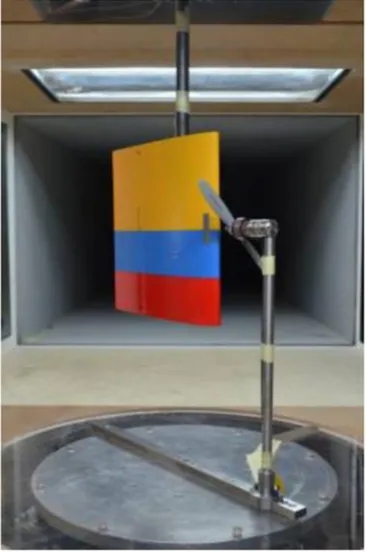
The experiment was set up in the closed-loop low speed
wind tunnel (SabRe) at ISAE as shown inFigure 1. There are
two tests which separate the wing from the propeller to measure the propeller wash effect. Hence, the propeller blows flow almost over the wing. From the results, it was found that the interaction between the wing and propeller is one of the main factors to be taken into account for the improvement of the aerodynamic performance of MAV. When a wing is added,
the complexity of the flow is increased by the influence of the wing over the propeller and the influence of the resulting combined flow of the propeller and the free stream over the
wing. It has been shown byCatalano (2004)that the position
of the propeller has an influence on the wing boundary layer characteristics, such as: laminar flow extension and transition, laminar separation bubbles and reattachment and turbulent separation. Also, Catalano shows that a pusher propeller configuration inflow affects the wing characteristics more effectively than the tractor configuration.
The flow simulation of the wing and propeller wash effect is
similar to the research performed by Ageev (2011). Ageev
investigated the aerodynamic performance of a disc-wing MAV with propeller in a Wing Slot. The propeller in this research was simplified to an actuator disk. And, in the study ofChoi and Ahn (2010), which considered the computation of aerodynamic influence of a pusher on a MAV, an actuator disk (AD) method was also used. However, this method ignores the number of blades, the rotation effect of the propeller and the viscosity of flow over the propeller surface. Therefore, using a real propeller to study the aerodynamic influence of a propeller on an MAV, by an unstructured overset grid technique, solves the limitations of the AD method.
According to the previous research, a limit was reached at low angles of attack, the maximum being 40°, which is near the wing stall. In fact, the tilt-body MAVs must be tilted from 0° to 90°, especially during transition flight, which is also important. Thus, this research has been conducted to study the wing behavior of this type of MAV. In view of this, a suggested way to simplify a propeller is to use an AD or an actuator volume (AV) to avoid the meshing of the real propeller. These methods save time, and the mesh model is not as complicated. However, some limitations still exist in this paper. For example, the AD requires the uniform pressure jump condition and the swirl velocity is ignored. These problems can be solved by the AV. But it also has a limitation because we are studying the influence of the incidence by keeping the propeller’s slipstream characteristics constant. Therefore, the AV will be applied to every incidence angle with the same conditions.
The AD technique is used for a propeller according to the
previous research byChinwicharnam et al. (2012a,2012a),
who studied the influence of the incidence angle by keeping
the propeller’s slipstream characteristics constant.
Additionally, the results of the simulations coincided with the experiment results.
Methodologies
The propeller for this simulation was simplified with an AD and an AV. The AD has a surface equal to the propeller’s diameter with zero thickness. It is defined by a constant pressure jump which can be calculated by the ratio of thrust
and propeller disk area (⌬P ⫽ T/S) as shown inTable I. The
Table I Thrust and pressure jump of actuator disk
AOA T (N) ⌬P (Pa)
0-80°/(ⴙ20°) 1.29 41.08
Figure 1 Propeller wash effect set up
Aerodynamic influence of interaction wing-propeller
Kwanchai Chinwicharnam et al.
Aircraft Engineering and Aerospace Technology: An International Journal
Volume 87 · Number 6 · 2015 · 521–529
propeller thrust was obtained by an experimental test performed in the ISAE low speed wind tunnel (SabRe). The test operational parameter used was a propeller regime of 5,000 rpm and a free stream velocity of 6 m/s at zero angle of
attack (Chinwicharnam et al., 2013). This value of the thrust
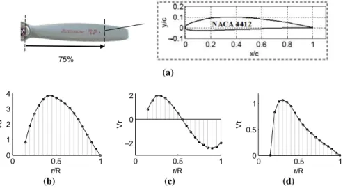
was applied to each angle. The AV represents the volume of the propeller while rotating. Normally, the thickness of the AV used represents the distance between the propeller blade leading edge and the propeller blade trailing edge. The boundary condition of the AV is used by the three polynomial velocity profiles, such as: axial velocity, radial velocity and
tangential velocity, which are calculated as suggested byRosen
and Gur (2008), as shown inFigure 2. The calculation of the profile uses the MATLAB program. And the aerodynamic forces in each blade section are taken from the Xfoil database, which takes into account any viscous effects. This technique implies that the real propeller is used. This causes the thrust loading and velocity to be non-uniform over the volume, including the swirl velocity, which is defined using the tangential velocity. These results are different for an AD. However, when the propeller has an incidence angle, the AV still has limitations in producing accurate results. Mainly because the BEMT-based program used to compute the three velocity profiles assumes that the flow around the blade azimuth is represented by the computed section. And this integration process makes it inapplicable for the case in the current study.
Experimental and computational analysis
Model configuration
As seen inFigure 3, the model is a MAV with a propeller in
tractor configuration. The wing profile is a symmetry airfoil NACA 0.012 and its aspect ratio is equal to 1. The model CAD used in the simulations was generated with the software
CATIA and is shown inFigure 3(c).
Geometric mesh model and boundary condition
An H-C-O grid structure mesh was used for the meshing of the model and the calculation space. The software ICEM program was used to generate the process mesh. The mesh
structure on the model is shown inFigure 4(a). The boundary
condition in this case of the domain is seen inFigure 4(b). The difference between the AD and the AV to represent the actuator’s boundary condition is mentioned above. All
simulations use the same size of the domain as 3.6⫻ 3.6 ⫻ 5.4
m. The total cells used are approximately 6.8 million elements.
In this case, the k- RNG model is suggested because the
RNG model in FLUENT accounts for effects of swirl or rotation by modifying the turbulent viscosity appropriately. A coupled scheme is used for the pressure–velocity coupling equation and the spatial discretization recommends using the scheme of the second-order upwind.
Computational convergence analysis
Three k-turbulent models are provided by FLUENT to solve the Navier-Stoke equations. All of them were applied to a wing prop-off with a steady state and the results are plotted in
Figure 5. This model is a rectangular wing with a low aspect ratio equal to 1. The free stream velocity is 6 m/s. The recommended computational domain size is 6 times the chord distance from the upper/lower wing surface and 12 times the chord behind the wing, giving a sufficient computational domain size for this calculation. The structured mesh is used
and the first layer from the wing surface is specified by Y⫹ ⫽
1, with the cell size growth ratio being 1.2. The total mesh suggests approximately three million cells. Additionally, the
accepted repetition is lower than 10⫺5 for every case of
calculation. The wing prop-off validation in this part shows
that the RNG k- gives the needed results of aerodynamic
force which coincides with the experiment data and are better
than the results with other models, as shown inFigure 5.
Figure 2 Thee velocity profiles of Graupner 8⫻ 6” at 0°, 5,000 RPM and 6 m/s for AV
0 0.5 1 0 1 2 3 4 r/R Va 0 0.5 1 –2 0 2 r/R Vr 0 0.5 1 0 0.5 1 r/R Vt 75% (b) (c) (a) (d) Notes: (a) Geometry of propeller simplified to NACA 4412 at 75 per cent of blade; (b) axial velocity; (c) radial velocity; (d) tangential velocity vs propeller radius ratio
–
AD and AV
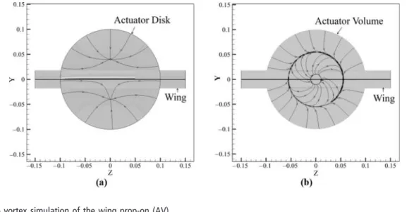
Path lines of flow which pass through the AD and the AV are
different, as shown inFigure 6(a-b). The AD ignores the swirl
velocity of the propeller, but the AV considers it. The path lines swirl along with the rotation of the AV and the center of AV has a small cycle due to the hub of the propeller. Moreover, it is quite difficult to clearly explain the swirl velocity of the propeller.
Figure 7shows the streamline of the model in variation of incidence angles at 0, 30, and 60°. The propeller is simplified through the AV. The wing tip votex is growing up with an increase in incidence angles. In general, the wing tip vortex is
generated because of the difference in pressure between upper and lower wing surfaces. In this case, the change in angle of attack increases the vortical lift of the wing, thus increasing the intensity of the wing tip vortices as well.
Results
The wing prop-off and prop-on were performed by steady flow computations using an incompressible flow condition within a range of angles of attack 0-80°. The numerical force results of the wing prop-off were matched with the experimental results. The wing prop-on was only validated at 0° because the thrust value was constant at every angle. Additionally, the AD facilitates this simulation of the propeller-wash effect as observed by the skin friction streamline on the wing surface and the static pressure distribution along the wing surface. Here, the wing prop-off is compared with the wing prop-on (AD and AV) at different incidence angles. Each has the same result, which identifies the wing stall angle at 40°.
Note, the comparison of static pressure on the upper surface
between wing prop-off and wing prop-on (AV) inFigure 8and
it can be found that:
● First, the wing prop-on is affected by the induced flow of
propeller; thus, the wing has the new increasing free stream velocity. This makes the pressure distribution lower than the wing prop-off.
● Second, while the propeller rotates, it normally has a down
going blade and an up going blade. This effect is produced by the in-plane free stream velocity component that appears as the angle of attack of the propeller is changed. Now, if the wing is cut at 50 per cent of spanwise to compare the left and the right side, it can be noticed that the pressure distribution of the wing prop-on (AV) is non-axis symmetric. This is the result of the blades going up and down in the plane of the propeller.
● Third, the pressure on the right side of the wing prop-on is
lower than the left side; this is because the flow velocity is faster at the side of the up going blade than the down going blade.
Skin friction streamlines
The skin friction streamline (also called shear flow streamline) gives some explanation regarding the flow around the wing surface, the reason for pressure distribution around the wing. Assuming the shear flow stays and covers the wing surface, the wing can generate a distribution of pressure. Consider the
Figure 3 (a) Tractor MAV configuration, (b) Model information and (c) CAD model
Figure 4 Structure grid
Figure 5 k-turbulent models comparison as V⫽ 6 m/s
0 20 40 60 80 100 –0.2 0 0.2 0.4 0.6 0.8 1 1.2 AOA, (°) CL Experiment RNG SST k-Spalart-Allmaras 0 20 40 60 80 100 0 0.5 1 1.5 2 AOA, (°) CD Experiment RNG SST k-Spalart-Allmaras (a) (b)
Aerodynamic influence of interaction wing-propeller
Kwanchai Chinwicharnam et al.
Aircraft Engineering and Aerospace Technology: An International Journal
Volume 87 · Number 6 · 2015 · 521–529
upper surface of the wing-alone case at 0-20° in Figure 8. First, the strong tip vortex of the wing is visible from the overlap of shear flow on the wing surface. Second, the free stream flow is close to the wing surface. These conclusions support the fact that the wing lift still increases with increments in AOA at post-stall. As the wing increases the angle of attack to more than 20°; the flows start disappearing from the wing upper surface, which is a cause of the decrease in the wing lift and the wing stalls. Notably, high incidence angles have a very high turbulent flow visualization; thus, the shear flow is very complex at the upper wing-alone surface, above 20 and 40°, for wing prop-on. The shear flows of the lower wing surface, with or without the propeller, flow smoothly due to their side position which attacks the free stream directly. Furthermore, the strong vortex is easily seen
because the wing has a low aspect ratio.Figure 8shows that
the shear flow over the wing in the case of the wing with AV is not symmetrical. The AV is specific with three velocity profiles and acts like a real propeller. Thus, the helix flow of propeller is considered to be the cause of the overlap of shear flow on the wing surface at every AOA.
Pressure distribution along wing area
A contour plot of static pressure distribution along the upper/lower surface of the wing prop-off and the wing
prop-on, varying the angle of attack from low to high, can
be observed inFigure 8. The static pressure of upper wing
prop-off surface decreases with respect to the incidence angle only in a range of 0-20°. At the same time, the static pressure on the lower surface of wing-alone increases with a
higher incidence angle. Therefore, the difference of
pressure between the upper and lower surface increases with respect to the angle of attack. It happens only in a range of 0-20°, because the wing loses its lift, and it will finally stall after 20°. This is proven by the onset of less shear flow on the upper surface of the wing, which makes the static pressure increase. Additionally, after reaching stall angle, the difference of static pressure between the upper and lower wing prop-off surfaces gradually reduces.
The wing prop-on at 0-40° findings are as follows. First, the upper wing prop-on surface has an average reduction of static pressure distribution, compared with the wing-alone case for each angle. Due to the increasing free stream velocity, which passes the wing, the wing is also influenced by the propeller-wash effect. Second, this effect decreases the static pressure on the upper surface with the increase in the incidence angle from 0-40°. And after 40°, the static pressure increases again. Third, this reaction confirms that the wing propeller stalls at 40°. In the same way, for the lower surface case, the static pressure
Figure 6 Path line of swirl velocity of (a) actuator disk and (b) actuator volume
Figure 7 Wing tip vortex simulation of the wing prop-on (AV)
distribution increases with an increase in the angle of attack, in average from 0 to 40°. After this angle, it decreases, due to the wing prop-on stalls.
Therefore, the different pressures between the lower and upper surfaces increase with the angle of attack, only in the range of 0-40°, and they decrease after 40°. This is a cause of wing stall. From this, we can show that the
propeller-wash effect improves the aerodynamic
characteristics of the wing by delaying stall and increasing the wing lift and drag.
The wing prop-on (AV) makes the pressure contour plot asymmetrical, for both the upper and lower wing surfaces. The cause is propeller position, which while rotating, has the blade going up and going down. The result is that the one side of the
wing has more free-stream velocity than the other side. That means that the angle of attack along the wing span is different,
as also shown inVeldhuis (2005).
Pressure distribution along chord wise
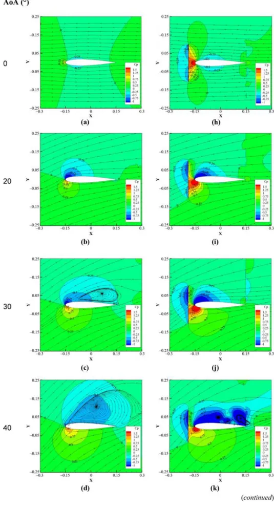
The static pressure contours are plotted along the chord section at the middle of the wing span, as shown in
Figure 9. The wing prop-off with 0°-80° present in Figure 9(a-g) compares with the wing prop-on in Figure 9(h-n). Herein, the propeller is represented by setting the boundary condition with the constant pressure jump. Hence, the pressure behind the propeller is higher than the front side,
because a propeller generates the thrust.Figures 9(aand h)
show that the color of upper and lower wings is similar in both
Figure 8 Comparison between the wing prop-off and wing-prop-on, in terms of shear stress streamline and pressure contour plot at wing
surface in variable AOAs
Aerodynamic influence of interaction wing-propeller
Kwanchai Chinwicharnam et al.
Aircraft Engineering and Aerospace Technology: An International Journal
Volume 87 · Number 6 · 2015 · 521–529
Figure 9 Static pressure distribution by contour plot along chord wise
wing prop-off and wing prop-on at 0° because the wing is a symmetry airfoil. For this part, the streamline is also plot; thus, it is easy to see wake and vortex. This phenomena in more dominant when the model is at a high angle of incidence. The difference between the static pressure on the lower and upper wing surface increases within a range of 0-20° for the
wing prop-off and 0-40° for wing prop-on inFigure 9. And
then it decreases with an increase in AOA, which is after stall angle of up to 80°. That means the stall angle is changed from 20 to 40° by the propeller-wash effect. Moreover, the maximum lift coefficient is higher by this effect as shown in
Chinwicharnam et al. (2013). The propeller-wash effect increases the free stream velocity and decreases the AOA of the wing. It can be seen by the contour plot herein as inFigure 9.
Figure 9
Aerodynamic influence of interaction wing-propeller
Kwanchai Chinwicharnam et al.
Aircraft Engineering and Aerospace Technology: An International Journal
Volume 87 · Number 6 · 2015 · 521–529
For example, the pressure distribution of the wing prop-on at 30° is similar to that of the wing prop-off at 20°. The free stream of wing with propeller-wash effect is higher and ignores the propeller. It is found that when the wing increases the incidence angle, the area of the wing on the upper surface experiencing a negative static pressure will increase due to the strong turbulent flow and the flow separation of the wing.
Conclusion
The flow simulation of the interaction between a wing and a propeller was performed. The incidence angles in this paper are in a range of 0-80°, which are higher than the ones mention in the literature reviews. The experimental tests results support that the propeller improves the aerodynamic performance of the wing by increasing the wing lift and drag, which delays the wing stall. Also, the stall angle of the wing prop-off and the wing prop-on coincides at the same angle, which is 20 and 40°, respectively. The simulation shows how the propeller delays the separation of the flow on the wing upper surface, how it promotes the reattachment of the boundary layer back close to the wing surface again at high incidence angle and how it increases the wing’s free-stream velocity by the propeller-induced flow. The results show how important it is to take into account the propeller flow when
designing a wing for a tilt-body or tilt-wing MAV
configuration. Taking into account the current development in smart materials and morphing structures, the understanding of such a complex flow as the one presented in the wing-propeller interaction of a tilt-body MAV will allow to implement smarter designs that will adapt during transition flight. The
knowledge gained about the flow behavior in the
wing–propeller interaction (as it is outlined in the current research) will allow implementing wing and propeller designs that are more adapted for tilt-body MAV applications. It should be noted that in this paper, the propeller is simulated by using an AD and AV, which is effective. However, some limitations still apply like the inability to simulate the effect of the angle of attack over the propeller blades, which makes the
propeller flow highly unsteady and non-axisymmetric.
Perhaps, in the future, the limitations can be overcome by using a real propeller or a more complex AD model.
Additional Source
The Graduate School of Kasetsart University.
References
Ageev, N.D. (2011), “Numerical investigation of disc-wing MAV with propeller in a Wing Slot”, Proceedings of the
International Micro Air Vehicles Conference, Harde, pp. 27-31.
Catalano, F.M. (2004), “On the effects of an installed propeller slipstream on wing aerodynamic characteristics”,
Acta Polytechnica, Vol. 44 No. 3, pp. 8-14.
Chinwicharnam, K., Choicharoon, A. and Thipyopas, C. (2012a), “Aerodynamic performance of multi-mission morphing wing MAV”, Proceedings of the International Micro
Air Vehicles Conference, Aachen, 3-4 July 2012.
Chinwicharnam, K., Choicharoon, A. and Thipyopas, C.
(2012b), “Aerodynamic analysis of MAVs wing
characteristics affected by propulsive induced-flow”,
Proceedings of the ICIUS Conference, Singapore, 22-24 October 2012.
Chinwicharnam, K., Gomez, D.A., Mochetta, J.M. and Thipyopas, C. (2013), “Aerodynamic characteristics of a low aspect ratio wing and propeller interaction for a tilt-body MAV”, International Journal of Micro Air Vehicle, Vol. 5 No. 4, pp. 245-260.
Choi, S. and Ahn, J. (2010), “A computational study on the aerodynamic influence of a pusher propeller on a MAV”,
Proceedings of 40th Fluid Dynamics Conference and Exhibit, 28 June-1 July 2010, AIAA, Chicago, IL.
Itasse, M., Moschetta, J.-M., Ameho, Y. and Carr, R. (2011),
“Equilibrium transition study for a hybrid MAV”,
International Journal of Micro Air Vehicles, Vol. 3 No. 4,
p. 229.
Rosen, A. and Gur, O. (2008), “Novel approach to axisymmetric actuator disk modeling”, Journal of AIAA, Vol. 46 No. 11, pp. 2914-2925.
Veldhuis, L. (2005), Propeller Wing Aerodynamic Interference, Delft University of Technology Netherlands, Netherlands.
Further reading
Filippone, A. (2013), “CFD actuator disk solutions for a helicopter rotor in hover flight”, Master thesis, UMIST, Stockholm.
Gomez, D. (2012), “Wake analysis of UAV propeller at incidence”, Proceeding of 47th International Symposium of
Applied Aerodynamics, 26-28 March 2012, Paris.
Gomez, D. (2013), “Study of the sensitivity to the lateral wind of a mini unmanned aerial vehicle with VTOL flight capabilities”, PhD thesis, ISAE, Toulouse.
McCormick, B.W. (1967), Aerodynamics of V/STOL Flight, Dover, New York, NY.
Ribner, H.S. (1943), Propellers in Yaw, NACA Rept. 820.
Corresponding author
Edgard David Gomez Ariza can be contacted at:davinciig@ yahoo.com