Development of a Force-Feedback
Laparoscopic Surgery Simulator
by
Ela Ben-Ur
B.S. Mechanical Engineering
Massachusetts Institute of Technology, 1997
Submitted to the Department of Mechanical Engineering in partial fulfillment of the requirements for the degree of
Master of Science in Mechanical Engineering at the
MASSACHUSETTS INSTITUTE OF TECHNOLOGY
September 1999
© 1999 Massachusetts Institute of Technology
All rights reserved
Signature of Author...
Certified by...
Department of Mechanical Engineering, July 28, 1999
.o Kenneth Salisbury, Jr. incipal Research Scientist
ohesis Supervisor
Accepted by...
Professor Ain A. Sonin Chairman, Committee on Graduate Students
MASSACHUSETTS INSTITUTE OF TECHNOLOGY
Development of a Force-Feedback
Laparoscopic Surgery Simulator
by
Ela Ben Ur
Submitted to the Department o-f Mechanical Engineering on August 6, 1999 in parcial fulfillment of the requirements for the degree of Master of Science in
Mechanical Engineering
Abstract
The work presented here addressed the development of an electro-mechanical force-feedback device to provide more realistic and complete sensations to a laparoscopic surgery simulator than currently available. A survey of the issues surrounding haptic (touch) displays and training for laparoscopic or "keyhole" procedures was performed. A number of primary and secondary sources including surgeon consultation , operating room observations, and task analyses were used to accumulate a list of needs. Subsequent requirements analysis translated these into a set of specifications for the kinematics, dynamics and actuators, and configuration of the device. These suggested a design with five actuated axes (pitch and yaw about the entrance to the abdomen, insertion, rotation about the tool axis, and gripper feedback) amenable to a configuration including two actuated tools in a lifelike torso.
These specifications were the basis for the generation and selection of design concepts. The
PHANTOM haptic interface from Sensable Devices was chosen from among a number of
existing devices and original designs to actuate the pitch, yaw, and insertion degrees of freedom.
A separate end effector actuator was specified to supply feedback to the handle rotation and
gripper. Mechanisms were proposed for each of these axes; a linear cable capstan was selected for the gripper and a cable capstan/drum for the rotation. The kinematics, bearings,
transmissions, and user interface for both axes were designed in detail, and first- and second-generation prototypes were built. The finished devices were integrated with the PHANTOM hardware, electronics, and software. Performance and design evaluations were performed, and plans for future device improvements and user studies were outlined.
Thesis supervisor: J. Kenneth Salisbury Title: Principal Research Scieptig
Acknowledgements
I extend my sincere gratitude to Ken Salisbury for granting me the opportunity to sprinkle my
engineering design pursuits with creative and humanistic moments through the wonderful field of haptics, and for going with me when they came along.
To Steve Dawson at Massachusetts General Hospital and Homer Pien at Draper Laboratory for bringing me on board this phenomenal project and helping to make everything happen, to David Rattner for his counsel and welcoming me to his operating room, and to the Center for
Minimally Invasive Therapies and the National Science Foundation for their financial support. To the extraordinary group that is "jks folks", whose limitless support enabled me to grow as a designer and as a person. Mark, for your mentorship and patience, Brian for your energy and confidence, Don for your unique perspectives, Andrew for being sensible, Jessie for being whimsical, and Arrin for being honest and just being there (in our office).
To professors Woodie Flowers, David Wallace, Warren Seering, Ernesto Blanco, and Anna Thornton at MIT and Tony Field, my studio head while at IDEO Product Devlopment, for helping me find a love and sensitivity for design, filling my toolbox, and instilling the importance of finding the right problem and doing things the right way.
To my lifelong friend, Jennifer Klein, for always helping me keep perspective and identity, and for continuing to support my creative side while becoming the artist and person I admire most. To my sister Nurit who is so much a part of who I am, and what I aspire to be.
And to my parents, Joseph and Tamar Ben-Ur, for their unconditional love, for everything they have given and given up, and for always trying to make the world a place where I could follow my dreams.
This material is based upon work supported under a National Science Foundation Graduate Fellowship. Any opinions, findings, conclusions or recommendations expressed in this publication are those of the author and do not necessarily reflect the views of the National Science Foundation.
Table of Contents
CHAPTER 1 PROBLEM IDENTIFICATION & BACKGROUND ... 8
1.1 THE PROBLEM ... 8
1.2 BACKGROUND AND M OTIVATION... 8
1.3 LAPAROSCOPY AND H APTICS ... 10
1.4 COM PONENTS OF A SIM ULATOR ... 12
1.5 PREVIOUS W ORK ... 12
1.6 H ISTORY OF THIS EFFORT... 14
CHAPTER 2 PROBLEM DEFINITION AND REQUIREMENTS ANALYSIS ... 15
2.1 REQUIREM ENTS D ATA A CQUISITION ... 15
2.1.1 Surgeon Input... 16
2.1.2 Operating Room Observations... 17
2.1.3 D ocum ented Task Analyses... 17
2.2 REQUIREM ENTS A NALYSIS... 18
2.2.1 W orkspace and Kinem atic Requirem ents... 19
2.2.2 Transm ission and Perform ance Requirem ents... 22
2.2.3 Features and Configuration Requirem ents... 26
2.3 BENCHM ARKING... 29
CHAPTER 3 CONCEPT IDEATION AND SELECTION... 31
3.1 PITCH, Y AW AND INSERTION... 32
3.1.1 Existing D evices and N ew Concept G eneration... 32
3.1.2 Concept Comparison and Selection ... 37
3.2 END EFFECTOR D EVICE... 38
3.2.1 Refocused Specifications... 39
3.2.2 D evice Configuration... 39
3.2.3 Actuation Concept G eneration and Early Refinem ent ... 41
3.2.4 Early Analysis and Concept Selection ... 42
3.3 D ESIGN SPLIT: 1 AND 2 D O F D EVICES ... 48
CHAPTER 4 DETAILED DESIGN AND FABRICATION... 49
4.1 G RIPPER A xIS DESIGN... 50
4.1.2 Shaft Constraint and User Interface ... 54
4.1.3 Cable M anagem ent ... 57
4.1.4 Actuation and Position M easurem ent ... 58
4.2 ROTATION A xis ... 59
4.2.1 Configuration and Bearings... 59
4.2.2 Shaft Constraint and User Interface ... 60
4.2.3 Cable M anagem ent ... 62
4.2.4 Actuation and Position M easurem ent ... 62
4.3 PHANTOM AND SIMULATION CONFIGURATION... 63
4.4 CONTROLS AND ELECTRONICS ... 67
4.5 SOFTW ARE ... 68
CHAPTER 5 EVALUATION AND RECOMMENDATIONS... 71
5.1 PERFORMANCE EVALUATION ... 71
5.2 DESIGN EVALUATION ... 73
CH APTER 6 CO N CLUSIO N S AND EXTEN SIO N S... 75
BIBLIO G RAPH Y ... 77
APPENDICES... 79
APPENDIX A .REQUIREMENTS ANALYSIS DATA COLLECTION FORMS ... 79
Al. Surgeon questionnaire ... 80
A 2. OPERATING ROOM OBSERVATION FORM ... 81
APPENDIX B. DESIGN SPREADSHEETS ... 82
B . Needs to M etrics ... 83
B2. Specification D efinition ... 84
B3. Benchmarking and Platform Concept Selection ... 85
B4. Gripper Subsystem Concept Selection ... 86
APPENDIX C. CA D DRAW INGS ... 87
C1. D OF D evice... 87
C2. 2D OF D evice... 93
APPENDIX D . DEVICE M ANUAL ... 99
Table of Figures
FIGURE 1-1. LAPAROSCOPY BEING PERFORMED, AND VIEW THROUGH THE LAPAROSCOPE IN HERNIA REPAIR. 10
FIGURE 2-1. AXES OF MOTION IN LAPAROSCOPIC SURGERY... 20
FIGURE 2-2. LAPAROSCOPIC SCISSORS CONSTRUCTION.. ... 21
FIGURE 2-3. EMPIRICAL TEST PERFORMED TO EXAMINE FORCE ON GRIPPER-ACTUATOR SHAFT. ... 23
FIGURE 2-4. TEST PERFORMED TO RATE FRICTION EXPERIENCED AT THE HANDLE IN TOOLS BEARING VARIOUS END EFFE CTO R S. ... 25
FIGURE 2-5. THE USE OF GRIPPERS TO SPREAD AND TEAR TISSUE IN CHOLECYSTECTOMY. ... 27
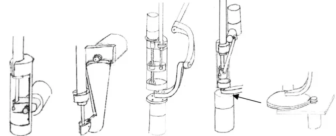
FIGURE 3-1. EXISTING SETUPS FOR ACTUATING THE PITCH/YAW AND IN SOME CASES INSERTION AXES. ... 33
FIGURE 3-2. COMBINED BEARING TO SUPPORT LINEAR AND ROTATIONAL MOTION OF THE TOOL SHAFT DEVELOPED BY TH E B LEU LER L AB . ... 35
FIGURE 3-3. CONCEPTS GENERATED IN BRAINSTORMING. ... 36
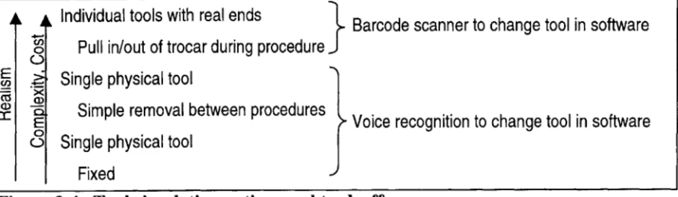
FIGURE 3-4. TOOL SIMULATION OPTIONS AND TRADEOFFS... 39
FIGURE 3-5. INITIAL BRAINSTORMING SKETCHES FOR THE END EFFECTOR DEVICE... 41
FIGURE 3-6. REFINED CONCEPTS. FROM LEFT TO RIGHT, LINEAR CAPSTAN, ARC-SECTION CABLE DRIVE, AND B A LLSC R E W . ... 4 2 FIGURE 3-7. ARC SECTION CABLE DRIVE SCHEMATIC.. ... 44
FIGURE 3-8. HORIZONTAL EXCURSION CONSTRAINT FOR ARC SECTION CABLE DRIVE CONCEPT... 45
FIGURE 3-9. UPDATED CROSS-SECTION CONCEPT SKETCH OF THE SELECTED CAPSTAN-BASED DESIGN. ... 47
FIGURE 4-1. MOMENTS AND CONSTRAINTS ON THE GRIPPER CARTRIDGE. ... 50
FIGURE 4-2. TWO BRAINSTORMING IDEAS FOR THE GRIPPER MOTION CONSTRAINT. ... 51
FIGURE 4-3. FIRST EMBODIMENT OF GRIPPER MOTION GUIDE. ... 52
FIGURE 4-4. FINAL LINEAR GUIDE DESIGN FOR THE GRIPPER CARTRIDGE.. ... 53
FIGURE 4-5. GRIPPER CAPSTAN DRIVE AXIS DETAILS... 54
FIGURE 4-6. OUTER SHAFT CLAMPING CONCEPT DEVELOPMENT. ... 55
FIGURE 4-7. INNER SHAFT CLAMP CONCEPTS... 56
FIGURE 4-8. CABLE FIXTURES FOR THE GRIPPER AXIS. ... 57
FIGURE 4-9. FINAL GRIPPER AXIS PROTOTYPE. ... 59
FIGURE 4-10. ROTATION AXIS DETAIL, AND AXIS SCHEMATIC... 60
FIGURE 4-11. PROGRESSION OF ROTARY CLAMP DESIGN. ... 61
FIGURE 4-12. ROTATION AXIS CABLE MANAGEMENT CONFIGURATION... 62
FIGURE 4-14. THE FINAL EMBODIMENTS OF THE I DOF (LEFT) AND 2DOF (RIGHT) DEVICES, INTEGRATED INTO THE
P H A N T O M G IM BA L... 64
FIGURE 4-15. COMPLETE 5DOF HAPTIC DEVICE. ... 65
FIGURE 4-16. Box SIMULATOR CONFIGURATION ... 66
FIGURE 4-17. SIMULAB TORSO (LEFT) AND LIMBS AND THINGS TORSO (RIGHT)... 67
FIGURE 4-18. COMPLETE SIMULATION SETUP ... 68
FIGURE5-1. CONCEPT FOR INCREASED DEVICE ACCESSIBILITY. ... 73
FIGURE 5-2. ORIGINAL AND REDESIGNED CABLE MANAGEMENT FOR THE ROTARY DRUM... 74
Chapter 1
Problem Identification & Background
1.1 The Problem
The motivation of this thesis was to develop an electro-mechanical force-feedback device to provide more realistic and complete sensations to a laparoscopic surgery simulator than currently available. This product development process presented two predominant challenges; the first was to understand relevant information about laparoscopic surgery and surgery simulation, and more specifically the critical requirements for this simulator. The second was to correctly
interpret this information in the design and construction of a device to successfully fill this niche.
1.2 Background and Motivation
There are as many motivations for surgery simulation as there are academic and industrial efforts to develop dedicated machines for individual procedures of all kinds. These benefits extend to patients and apprentice surgeons alike, and as such providers of medical insurance stand to gain as well.
Most readily apparent is the interest in improving surgeon education. One advantage of surgical simulators is that they can be made available at any time to make frequent, self-paced practice possible for learning surgeons as well as experienced surgeons who may wish to practice a new surgery several times before performing it on a patient. This serves as a favorable
contrast to the current "see one, do one, teach one" method which is restricted by the availability of operations which may be used as teaching cases, and which places a great deal of pressure on a new surgeon. Furthermore, simulators provide an opportunity for standardized, objective, and quantitative evaluation and feedback based on positions and forces which characterize the surgeons' motions. Such information, including time on task, accuracy, peak force applied, tissue damage, and position error (Rosen et al, 1999), may be potentially used not only to give feedback to the learning surgeons about their performance and progress, but for testing,
licensing, and re-validating surgeons. Simulators are also capable of presenting the trainee with multiple surgery scenarios, conditions, and pathologies that might be found in a real operating room (OR) with a real patient, but which are difficult to recreate with a cadaver, such as the onset of internal bleeding. Furthermore, they provide the opportunity to approach the same procedure multiple times in order to explore various surgical options. At the same time, simulation can decrease the time and cost associated with training for medical procedures, a matter of great importance to teaching hospitals in which resources must be distributed between patient care and education obligations (Caroll, 1994).
The real indicator, however, is the benefit to patients, and insurance providers are quick to help define these advantages. It is clear that better prepared surgeons can make a critical
difference to the success of an operation, particularly in complicated procedures. Furthermore, the current practice of teaching through "on-the-job training " (Rattner interview, 1999) can put patients at greater risk and result in unnecessary trauma to both trainee and patient. The use of simulator training prior to OR training may reduce the number of surgeries performed as "training cases" and allow students to initiate work on live patients when their skills are more developed.
1.3 Laparoscopy and Haptics
Laparoscopic surgery, considered here, amplifies some of these motivations since it is a particularly difficult procedure for the surgeon but provides many benefits to the patient. Laparoscopy is one of several types of minimally invasive surgery (MIS), which seek to
minimize the size of incisions and exposure to infection by inserting tools into the body through either natural orifices (endoscopy) or tiny incisions with sealed ports (laparoscopy). One of these tools is generally a suitable camera (endoscope or laparoscope), and the surgeon performs the operation while watching this interior view on a monitor. In laparoscopic surgery, shown in Figure 1-1, one or more small incisions are made in the abdomen and a trocar, or plastic port, is inserted in each. Through the first, the laparoscope is passed to provide an image of the inside of the body on a monitor. Additional trocars are placed, and tools among a family of 33 cm long,
5-10mm diameter surgical instruments, are inserted as needed to perform the operation. In the course of the operation, the surgeon is frequently working with two toolhandles while looking away from the patient at a monitor.
Figure 1-1. Laparoscopy being performed, and view through the laparoscope in hernia repair (Laparoscopy.com, 1999).
This configuration introduces several complications which require extraordinary hand-eye coordination. First, the surgeon is required to work in 3D while receiving only limited 2D
visual feedback on the monitor. Second, the surgeons work with long tools, for which the entry point into the body becomes a pivot. Consequently, motion of the surgeon's hands is reflected inside the body: when the hands move left, the tool moves right, and vice versa. Finally, maneuverability and access inside the body is significantly limited relative to surgery using traditional tools (Burdea, 1996), (Caroll, 1994).
However, the gain in terms of increased patient comfort and reduced risk, recovery time (patients often leave the same day), and scarring make laparoscopic procedures more than worthwhile. Increasing pressures to reduce hospital stays and related health care costs have promoted increasing use of minimally invasive procedures including laparoscopy. Under such motivation, engineering efforts have continued to produce new tools and procedures to further reduce patient trauma and risk. However, the added complexity and new procedures have stood as a barrier to the dissemination and acceptance of new technology in the medical community; a method of continuing education, which can be greatly facilitated through simulation, is pivotal to facilitating continued progress in medical care standards (Edmond et al, 1997).
As mentioned above, these new minimally invasive techniques place additional demands on surgeons' already impressive hand-eye coordination skills. Such skills are most rapidly acquired and internalized through hands-on "going through the motions", that is, practice makes perfect. As discussed earlier, simulators make it possible to practice more different procedures more frequently. However, an issue which was not certain, but very relevant to the current research, was the importance of haptic, or touch, information both in learning and performing laparoscopic tasks. The work of doctors at Penn State University College of Medicine revealed that haptic "learning" does occur as surgeons learn their trade. Experienced surgeons were much better at identifying shape and consistency of concealed objects using laparoscopic tools than medical students, and in some cases could identify grades of sandpaper as well as with an ungloved hand. (Gorman et al, 1999)
Given that haptic information is significant in surgery, it follows that providing accurate haptic sensations to surgeons as they practice is essential. There is potential for simulators to provide more accurate experiences to novices than currently available pre-OR training methods. Existing methods include the use of commercially available synthetic torso and organ models
intended for laparoscopic training, as well as cadaver or animal dissection. Synthetic and nonliving tissue can have dramatically different mechanical characteristics than live tissue, and live animal dissections are being phased out for ethical reasons. Finally, displaying tissue property data taken from live human tissue through a simulator can offer more realistic reaction forces to the student than working with these materials.
1.4 Components of a Simulator
The task of simulating both the visual and haptic sensations of surgery dictates a basic set of elements for any simulation system. Generally speaking, these components involve input/display devices and a computer which controls the simulation. Graphics display is provided by a
computer monitor, and haptic display through an electro-mechanical force-feedback device, usually specialized for the type of surgery being simulated. The user interacts with the
simulation through the haptic device, which measures the instrument position in the simulated workspace. The computer runs real-time software which uses this position (and its derivatives) as the input to tissue models based on simple mass-spring-damper relations, Finite Element methods, or other techniques to determine the geometric and dynamic behavior of the simulated tissue. These reactions are fed to software loops which continuously update the commands to both the graphical and haptic display devices.
1.5 Previous work
Extensive effort has gone into the development of each of the basic simulator system elements described above. As the present research was focused on the haptic display device, it is helpful to discuss significant work in this field.
Force-feedback devices as a field grew out of efforts initiated in the 1950's and 1960's to develop "master" manipulators for telerobotic applications. In these systems, a human interacts with the master device in order to control a second "slave" which performs a task. Telerobotics are generally implemented in environments unfavorable for human manipulation due to harmful
environmental factors or motion constraints, or for tasks that a robot can be specialized to perform. These input devices took on various forms: devices morphologically similar to the slave, joysticks, exoskeletons which encased the hand or more of the body, and more generalized kinematic configurations. (Madhani, 1998), (Burdea, 1996). The observation that human
performance could be significantly improved by providing force feedback to the system user could be directly mapped into later efforts to develop masters to interact not with a distant real environment but with simulated or "virtual". This led to the introduction of generalized force-feedback manipulators for virtual reality such as the PHANTOM haptic interface which would be the basis for a number of the systems described here (Massie, 1993).
The same trend can be seen for the field of medical robotics in particular. Force feedback telemanipulator systems have been introduced to permit motion scaling and filtering for
microsurgery and to relieve the kinematic constraints on the surgeon in laparoscopy. Examples include an opthalmic telerobotic system developed by Ian Hunter at MIT and a laparoscopic system designed by Akhil Madhani in the MIT Haptics Lab (Madhani, 1998). In such systems, forces reflected to the user can actually be amplified to effectively give the surgeon a "super-human" sense of touch and better control when working with delicate tissues. Some efforts to bring force-feedback into the surgery simulation arena have produced a variety of dedicated haptic devices while others, focusing on achieving sophisticated modeling and graphics, have taken the step of integrating one of these devices into their simulations. These configurations are predominantly 3-actuated-degree-of-freedom (pitch, yaw and insertion) devices which either actuate around the pivot point or can apply forces to the tool tip. Examples of the former include the commercially available Immersion Impulse Engine and the Force Feedback Device
developed by Hauptabteilung Ingenieurtechnik. Devices which apply forces to the tool tip include a recent patent by Immersion Corporation (#5,828,197) (Martin, 1996) and the
PHANTOM Haptic Interface made by Sensable technologies (Massie, 1993). A 2 DOF
pitch-yaw device was developed by the University of Hull, and 6 DOF device using three parallel linkages and no trocar was implemented by the University of Tsukuba (Asano, 1997). Finally, the laboratory under Professor Bleuler at the Ecole Polytechnique developed a 4 DOF (pitch, yaw, insertion, and roll) device in which the first three axes are actuated similarly to the
devices which have been implemented by developers of full software simulations in order to provide force feedback for their systems. Thus, most simulations have feedback to the pitch, yaw, and insertion axes of motion, while the rotation of the tool and the opening and closing of the handle are passive. The device from the Ecole Polytechnique uses a crossed-roller
configuration to introduce actuated tool rotation in parallel with the actuation of the insertion axis. Andrew Mor at Carnegie Mellon University made an interesting extension for the purposes of an arthroscopy simulator by providing feedback to the x-y positioning of the port using a pantograph planar linkage, thus actively simulating the reactions of the abdominal wall. These devices will be examined in light of specific system requirements in Chapter 3.
1.6 History of this Effort
The current effort was initiated by radiologist Dr. Steven Dawson with the Center For Innovation in Minimally Invasive Therapies (CIMIT) with the goal of taking laparoscopic simulation to a new level of "reality". A team led by Homer Pien at the Draper Laboratory was enlisted to tackle the formidable software challenges posed by developing the computer model for both the graphics and haptics simulations. The MIT Haptics Laboratory was presented with two tasks that would be no less exciting from an electro-mechanical design standpoint. The first involved the development of a new force-feedback device to make it possible to display complete and high-fidelity touch in such a simulation while disguised in a realistic setting including surgical toolhandles and a human torso model. The second was to design one or more instruments for measuring tissue mechanical properties that could potentially be inserted through a trocar port to gather data from a living human. In this thesis, the author undertook the creation of the first device as a complete product design process from front-end task analysis through design, realization, and evaluation. Chapter 2 of this document details the sources and analysis of
information used in design decision-making. These design strategy considerations are described in Chapter 3, while more detailed mechanical design and electronics/software integration is
discussed in Chapter 4. Evaluation of, and recommendations for, the device based on both technical specifications and user expectations are presented in Chapter 5, and this assessment is the basis for conclusions and extensions discussed in Chapters 6.
Chapter 2
Problem Definition and Requirements Analysis
The most important and success-determining step in the development of a new product is the careful definition of the need or problem that the product serves; subsequent development must keep this need and associated requirements in constant sight. While absolute realism might ostensibly be assumed as the goal for a simulator, it is useful to precisely recall the function of the device in question: an educational laparoscopic surgery simulator. Requirements analysis for this project focused on understanding not only the elements of laparoscopic surgery but which of these elements are important for learning this complicated art. It was in fact possible to find a
single underlying design problem to which all future design decisions could be submitted. While it was clear that ultimate realism would be an exciting achievement, and that high-fidelity haptics could be pivotal in teaching the nuances of procedures and distinguishing between healthy and unhealthy tissue, the single most important element of the learning surgeon's education is the development of a "systematic approach to problem solving" (Rattner interview, 1999).
2.1 Requirements Data Acquisition
Information about the qualitative and quantitative design requirements for the simulator hardware was investigated through several major sources: interviews, OR observations and documented task analysis.
2.1.1 Surgeon Input
The first resource for requirements information was expert testimony. Interviews were
conducted with David Rattner, a pioneering laparoscopic surgeon at the Massachusetts General Hospital, and Steven Dawson, an interventional radiologist, also at MGH, who was the drive behind the development of this simulator. The questionnaire used as the framework for these interviews can be found in Appendix Al. It was designed with a common customer interview rule of thumb in mind: people are much better at recognizing features they do not want than at visualizing their ideal product. In addition to background questions about current training methods and other simulators they may have used, the doctors were asked directed design-driven questions which were structured in three different ways. The first set were yes/no questions regarding the importance of a number of technical parameters (use issues, workspace,
configuration, feedback modes, etc.) to the effectiveness of a laparoscopic trainer. The second presented pairs of options for simulator configuration and required the interviewee to indicate which would be preferable. The final set listed major areas of design latitude and gave them the opportunity to suggest a "wish list" for each.
While detailed comments and requests will be categorized in the following section, it is worthwhile to make several general observations. The first of these is that the "important or not" and "choose one" questions type generally elicited a confident, detailed, and articulate response, while the doctors found it more difficult to describe their "wish list" even given specific topics. Second, haptic sensations appear to be very difficult to describe in an abstract, removed sense and are closely coupled to the context in which they are experienced. For example, there were a number of questions related to workspace and forces that Dr. Rattner, despite his vast
experience, was better able to answer in the operating room with the tools in hand than in the preceding office interview. Similarly, while Dr. Dawson had drawn the conclusion from testing non-surgical PHANTOM demonstrations that this device was inappropriate for use in surgical simulations, when presented the same device with a laparoscopic tool attached and a more organ-like demonstration he was better able to assess the PHANTOM's potential as the fundamental actuator for a simulator.
2.1.2 Operating Room Observations
The second major activity in data collection was observation of Dr. Rattner performing laparoscopic hernia repair and gallbladder removal (laparoscopic cholecystectomy or "lap choly") in the operating room. These observations were performed twice in the course of the project: first at the start of the work and again after the device concept had been chosen but before detailed design decisions had been made. Both visits provided the opportunity to observe "training cases" in which an apprentice surgeon was present. In these cases Dr. Rattner was particularly careful in his narration of the procedure, and the student would perform segments of the operation under his guidance. The first visit was an instrumental in gaining familiarity with laparoscopy and associated terminology, instruments, and procedures, as well as in assessing preliminary parameters such as workspace, frequency of tool and port changes, and so on. These insights were invaluable during the generation and selection of design concepts. As the issues to be addressed in detailed design became clearly defined, it was possible to develop a directed task analysis study to address specific questions about design parameters. The operation observation form created for this purpose can be found in Appendix A2. The first part of this form was dedicated to recording the time spent by the surgeon manipulating tissues in specific ways which would place requirements on the simulator: grasping, cutting, and twisting. The second part prompted for observations regarding tool insertion points, removals, proximity and ranges of motion. The final element of the observation was the recording of the proceedings of the operation, including tools used, tasks done, and any comments made, particularly to the student surgeon.
2.1.3 Documented Task Analyses
Verbal and pictorial description of laparoscopic procedures can be found in various surgery texts, and excellent photograph and video coverage of many procedures is available online at
www.laparoscopy.com. Cao, et al. (1996) breaks the procedures of cholecystectomy, inguinal hernia repair, and fundoplication (placing wrap around esophagus) down into a hierarchical set of steps and tasks, and measures the time surgeons spend in each over the course of an operation.
A study carried out by Rosen, et al (1999) also presented a timed state analysis of the procedures
strain gauges to record surgeons' force profiles during actual cholecystectomy and
fundoplication. Finally, Gupta, et al (1997) recorded forces applied to the laparoscopic handle during manipulation of various inanimate objects.
2.2
Requirements Analysis
Not surprisingly, a large amount of relevant data was collected from these three sources. The integration, organization, interpretation, and quantification of this information, as well as its application in concept selection, were carried out in several design matrices which proved to be powerful tools for maintaining the focus and integrity of the design process. These matrices were based on those suggested by Ulrich and Eppinger in their book Product Design and
Development (1995) which is widely used as a product development text and guideline.
However, the spreadsheets used here were somewhat customized, reflecting only the front-end design stages relevant to the current project, and frequently combining the operations of several suggested matrices into one matrix. These spreadsheets have been compiled in Appendix B in order to provide a concise and coherent summary of the decision-making process which led to the final design.
The first of these, entitled Needs to Metrics and found in Appendix B 1, served as a forum to translate coimrhents and observations into metrics relevant to design. Each was stated as a concise need and placed listed by source in the rows. Design metrics were added in the columns as new ones were suggested by reading through the needs. Darkened cells represent each of these correlations. Where possible, a numerical value was introduced to quantify this relationship in the spreadsheet Specification Definition found in Appendix B2.
In order to meaningfully process this wealth of information, each metric was associated with one of three major kinds of design parameters that would be addressed. These were workspace and kinematics, performance and actuation, and features and configuration.
2.2.1 Workspace and Kinematic Requirements
The first set of design considerations addressed the demands of replicating the workspace and axes of motion present in laparoscopic surgery, and would significantly impact the kinematic structure and axes designs chosen for the device.
The permissible size "box" for the device was governed by the desire to maintain the visual integrity of the simulation environment as well as to keep the setup relatively portable. Preferably, one or two such devices would fit beneath a human torso model, or alternately one with drapes lying across a width similar to that of a hospital bed, 3 feet across. The maximum total footprint for this machinery was then 1.5'x2'. The working volume of a surgical procedure varies somewhat with the type of surgery being performed, as does the location of this volume within the abdomen. The volume associated with the hernia repair was roughly 6"x3"x2" near the abdominal wall, whereas that used in the cholecystectomy was smaller, roughly 4"x2"x2", and deeper within. Each device was to be responsible for the workspace of only one of two tools generally held by the surgeon. If the device was to remain in one position, its workspace would be required to be large enough to reach the areas of all procedures to be simulated; if the device could be moved between simulations of different procedures, only the largest individual
operation volume would need to be considered. Both doctors indicated that it would be appropriate for a given simulator setup to be dedicated to a set of procedures with similar workspace constraints; as such, the minimum working volume was taken to be 6"x6"x6". A subsequent specification was that hardware could not extend above the simulated interaction point by more than about 2". This figure was achieved by considering the length of trocar typically inside the abdomen, about 3", and assuming that while some may be cut back in order to allow the interaction point to approach the end of the simulated trocar, around 1" should be left inside to secure the trocar.
Z
x y
Figure 2-1. Axes of motion in laparoscopic surgery
The fact that the primary motions involved in minimally invasive surgery occur through a point constrained in the plane of the entrance to the body (a 2-dimensional constraint) reduces the degrees of freedom of the system to 4 from the 6 of an unconstrained spatial system. The remaining degrees of freedom for the laparoscopy tool as a whole include pitch and yaw
rotations about the x and y axes, roll rotations about the z or toolshaft axis, and translation along the z axis, as defined in Figure 2-1.
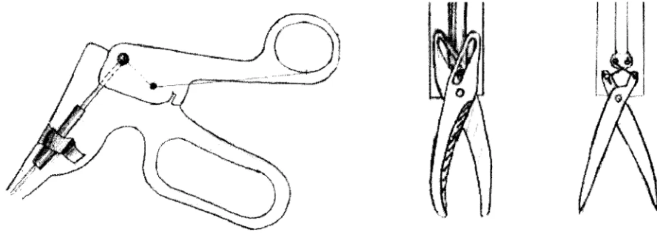
In addition, many tools have an end effector which is controlled by a squeezing/opening motion of the tool handle. The details of a scissors tool are shown in Figure 2-2 below.
A'N
Figure 2-2. Laparoscopic scissors construction. The handle is at left, and end effector mechanisms from an AutoSuture tool and an Ethicon tool at right.
In general, the handle incorporates a lever which amplifies the force applied by the human hand
by a factor of around 4 and transmits this force to an inner shaft which runs the length of the tool.
The motion of this inner shaft relative to the outer shaft is used to actuate any one of a family of lever-based tools, but most frequently graspers and scissors. The travel of the inner shaft is dependent on the individual lever design for the brand of tool: for AutoSuture tools this was 6mm, whereas for Johnson & Johnson Ethicon tools it was only 2mm. The finger loops of the handle are actually decoupled from the twisting of the shaft, which can be controlled by placing the index finger on a wheel at the top of the shaft.
In total, there are five degrees of freedom to a laparoscopic tool. The comments from the doctors, as well as observations in the operating room, made it clear that the insertion force, pitch and yaw torques, and the gripper force are all significant in surgery and training. Active twisting along the tool axis was not apparent in the two procedures observed in the OR, but the doctors provided assurance that such torques are exerted in other procedures.
The next set of parameters to consider were the ranges of motion of each of the degrees of freedom, which can be deduced in part from the size and location of the work volume. Again, these varied with the procedure performed. Pitch and yaw motions reached a maximum of 60 degrees from vertical during cholecystectomy and as much as 80 or more degrees during the exploratory phases of the hernia repair. The tool insertion setpoint for a surgery varied between
near the surface (the tool frequently retracted into the trocar) for hernia repair to as deep as 6 inches during cholecystectomy; deviation from this point was around 3 inches in both cases. Finally, the maximum displacement for the roll axis, that is the extent to which the surgeon twisted the tool, was less than 90 degrees to either side of the rest position, or a total of 180 degrees of motion. It was verbally verified that there is rarely cause to rotate the tool more than this, and it is never rotated greater than 360 degrees.
The proximity with which two tools may approach, or appear to approach, one another placed much more stringent constraints on the volume of the device. Dr. Rattner emphasized to his pupil the need to use the tools "like chopsticks and spread" tissue during exploration in the hernia repair operation. In this process, the tools are crossed and come within 1-2 centimeters of one another. However, tool proximity was not as marked in the cholecystectomy.
2.2.2
Transmission and Performance Requirements
The second major set of considerations for which it was desired to gather information dealt with decisions that would have to be made regarding components (motors, encoders) and properties (backlash, backdriving force) of the servo loop.
2.2.2.1 Maximum Forces and Torques
The first of these were the maximum forces and torques applied to each axis of motion, and the duty cycle with which these were applied. As a first reference, the two aforementioned
publications were consulted. Rosen, et al (1999) measured X-Y (plane perpendicular to the tool) forces and torques, Z (insertion) force, and the force along the inner gripper-actuated shaft during the grasping-pulling state of an actual laparoscopic procedure. Because this state placed
significant demands only on the insertion and gripping axes, only those measurements were considered as envelope requirements. Gupta, et al (1997) made measurements of force applied to handle of the gripper during contact with materials such as cotton and PVC gel; although neither
a specific lever ratio nor distance of the measurement from the fulcrum were given, this value could be compared to the inner shaft force by multiplying by a "worst case" ratio of 4:1. The two studies were fairly consistent, and suggested a maximum gripper shaft force of 17N (Rosen
et al, 1999), (Gupta et al, 1997). In order to achieve an idea of what this force would feel like to
the surgeon, and as a rough check of these values, an empirical test was performed by
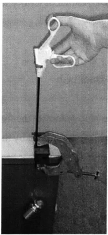
suspending the corresponding mass from the inner gripper shaft while clamping the outer shaft to a table as shown in Figure 2-3.
Figure 2-3. Empirical test performed to examine force on gripper-actuator shaft. A significant amount of force was required to lift the weight by squeezing the handle; this
appeared to be an appropriate upper bound (before safety factors) for a design force.
The insertion force documented by the University of Washington study was 17N. In order to verify this value as well as to better understand appropriate pitch/yaw torques, a
PHANTOM was placed inside a box, and a laparoscopic tool inserted through a trocar in the lid
and attached to the end of the PHANTOM gimbal. This setup was able to apply an effective insertion force and pitch-yaw torques to the tool handle. A simple demonstration simulation consisting of a large pink sphere of roughly "organic" stiffness (0.1 N/mm) was presented to Dr. Dawson. He was satisfied that the forces and torques which he experienced were as large or larger than those encountered during surgery. The PHANTOM can exert 8.5N in each translational direction, and the tool mechanical advantage in the pitch/yaw lever across the fulcrum reached a maximum of about 4:1.
Since the surgeon resists twist moments by placing a finger on the twist wheel, a
maximum force of 6N was empirically chosen by the author, and would be applied at a radius of approximately 1.3cm, the radius of the wheel. Accordingly, a torque of 0.08 Nm was specified.
When questioned in the OR, Dr. Rattner described the forces in general as "very light" and could be seen working very delicately. A visiting surgeon from the Philippines confirmed this, saying that there is "no real resistance".
2.2.2.2
Backdrive Friction and Backlash
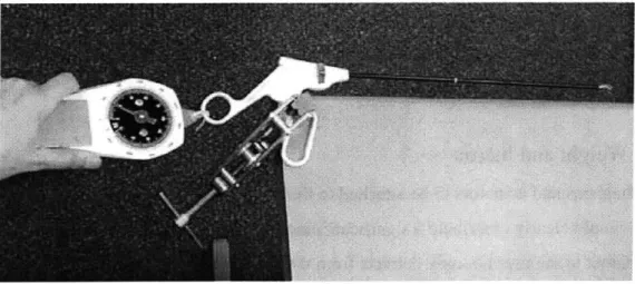
For haptic devices in general, it is a goal to minimize the force required to backdrive the system resulting from friction and inertia in the device, scaled by the transmission ratio squared when reflected to the user, and in the transmission itself. This force will be felt in addition to the simulated forces displayed, and will be present when the user is moving in simulated "free space". For generalized haptic devices like the PHANTOM, it is desired make backdrive friction as close to zero as possible for all axes. Because the present system was to work in conjunction with an actual, non-ideal, laparoscopy tool, this requirement was examined in more detail. In actual surgery, the trocar is able to pitch and yaw freely within the constraints of the abdominal wall. A fair amount of friction is associated with the insertion axis, however, due to the sliding of the tool shaft against the seal in the trocar. Since a realistic setup was required, it was assumed that this friction would be present as a consequence of using an actual trocar and tool, and that additional friction should be avoided. As regards the gripper axis, detectable friction is contributed by the linkage which drives the end effector in either grippers or scissors, and the sliding of the curved surgical scissors blades on one another made an additional significant contribution. These observations were quantified by clamping the stationary finger loop to a table and pulling on the mobile one with a spring scale with just enough force to keep the handle moving at a constant rate, as shown in Figure 2.4.
Figure 2-4. Test performed to rate friction experienced at the handle in tools bearing various end effectors.
It was found that scissors, which required 2.5 N, were characterized by dramatically greater
friction than graspers which required 0.4 N, and that removing the end effector and linkage completely resulted in markedly lower friction than either tool, requiring less than 0.001N. As a result, it was concluded that an actuation scheme incorporating the tools as is should add no additional friction to this axis, but one which drove the inner shaft directly could have as much friction as the lowest-friction tool, graspers. The rotational axis of the tool carried an amount of friction as well, but this was part of the handle, which was assumed to be part of the final simulator. Consequently, friction in this axis was also to be minimized unless the handle would be altered by some method to compensate.
Similarly, in generalized haptic devices, it is desired for backlash in the system, as perceived by both the servo loop and by the user, to be zero. The latter constraint, that backlash between the position measured by the system sensors and the actuators be zero, was very much in effect for this project as well. Backlash at this point can cause instability in the servo loop because of the force nonlinearity caused by the delay in actuator engagement and because of the discrepancy between measured and actual position. The implications of this constraint were that backlash in the transmission between the motor and the measured position had to be minimal. However, a large amount of backlash is present in the lever and rotary dial mechanisms in the handle of the laparoscopic tools. There was 0.4 mm play in the gripper shaft travel, and 28
degrees of play was measured in the rotation dial. This backlash is apparent only to the user; it could and in fact should be left as is, since the surgeon's own internal "servo system" must be trained to compensate for this backlash.
2.2.2.3
Weight and Inertia
The mechanisms and actuators to be attached to the laparoscopic tool in order to provide force feedback would clearly contribute a significant amount of weight and inertia to the tool. Having these apparent to the user not only detracts from the realism of the simulation, but can contribute to muscle fatigue, particularly if the user must apply a constant force to support the weight of the
device. If the simulator did add to the weight of the tool, then gravity compensation, or the application of a constant force equal to the additional weight in the vertical direction, could be implemented in software, or the weight could somehow be physically counterbalanced. Neither solution was ideal; gravity compensation requires constant effort from one or more actuators, and may require that this actuator be more powerful than otherwise necessary. Counterbalancing the weight contributes to the inertia of the system. Neither method is able to compensate for the apparent increase in inertia. Thus, it was a goal to minimize the weight of the device. This goal was generally consistent with a second requirement, that the inertia of the elements in each individual transmission be minimized in order to prevent excessive reflected inertia in any actuated axis.
2.2.3 Features and Configuration Requirements
The final set of requirements dealt with overall configuration options and alternatives for
features and methods of use. As such, the source for this information was almost exclusively the opinions of the doctors.
The first group of these specifications pertained to the details of application of force-feedback in the simulator. Foremost was the question of how many of the 5 degrees of freedom in laparoscopy described earlier were to be actuated. The need for pitch/yaw and insertion feedback was immediately clear. As concerned the gripper axis, Dr. Dawson emphasized the need to be able to "feel increasing thickness", and it was observed in the OR that graspers were
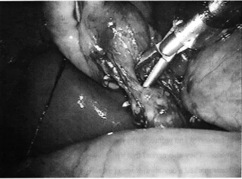
used not only to squeeze but also to spread and separate tissue, referred to as blunt dissection, as demonstrated in the cholecystectomy pictured in Figure 2.5.
Figure 2-5. The use of grippers for blunt dissection in cholecystectomy (Laparoscopy.com).
Simulating such experiences clearly called for actively driven feedback to the gripper axis, since they could not be supplied by a mechanical spring or damper and these would in any case need to be coupled to a clutch of some sort to simulate empty space. Furthermore, both doctors stated that although less predominant, sensation from the rotation axis was nonetheless important in surgery and should be actively driven if the simulation was to be complete.
A subsequent issue was that of which laparoscopic tools were to be simulated. Dr.
Dawson suggested three which would require gripper feedback, locking and non-locking graspers and scissors, as well as a scalpel. Furthermore, he specifiedj that the difference in
internal friction between the grasper tool and the scissors should be maintained. Another issue of concern regarded whether rigid objects, such as in the occurrence of the tools coming into
contact with one another or with bone, would need to be simulated. Both doctors commented that these interactions do not occur in normal laparoscopy, but that it was for this very reason that they should be possible at least for pitch/yaw and insertion; the student surgeon should have immediate haptic feedback to indicate that such an error was made.
The next set of concerns regarded interface issues, and the paradigm for the use of the simulator. From the doctors and the surgery manuals it was understood that while port locations differ between different types of surgery, they are consistent within a particular procedure. Dr. Dawson specified that these locations should be changeable easily between simulations. With regard to the need to have the tool completely removable during simulated tool changes within a surgical procedure, Dr. Rattner commented that the important component that must be learned is
the re-registration of the tool position after it has left the viewing area of the laparoscope. He
confirmed that the physical act of inserting and removing the tool from the trocar was
insignificant, and that requiring the student using the simulator to extract the tool to the edge of the trocar and out of the "field of view" before commanding a tool change would be appropriate. Both doctors agreed that a voice activated software tool change would be optimal at this point; when the tool was reinserted and reentered the field of view it would appear on the simulation display as the new tool. They also agreed that while having a single toolhandle instead of an array of surgical tools marked a deviation from a perfectly simulated OR, it would streamline the use of the simulator and reduce the number of components that might become broken or lost. Since the initial setup and possibly frequent movement of the tool between ports would likely be performed in an non-engineering setting, it was essential that this coupling be simple and robust and that it require at most one, preferably standard, tool. Additionally, the setup was to be as portable as possible.
A somewhat more subjective, but no less important, concern was the external appearance
of the simulation. While Dr. Dawson envisioned a setup that could fit on one of an array of tabletops in a classroom as well as in a simulated OR setting, the station itself would be expected to maintain the visual integrity of the surgical environment. The exterior interface was to be a real laparoscopic tool handle emerging from a real trocar inserted in a lifelike human torso model, possibly including the drapes and covers used in the OR. Consequently, all hardware would have to reside beneath the torso model, and no visible instrumentation could be placed on the tool handle. The question was raised as to whether it would be appropriate to allow wires to emerge from the electrocautery port on the handle (to which in reality wires are attached during cautery); to this Dr. Rattner answered that the process of attaching and detaching the cautery wires, and learning to remember to do so, were essential, so this was not a possibility. Finally,
although Dr. Rattner commented that compliance of the abdominal wall, in which the trocar pivots, was not important, Dr. Dawson specified that if possible a model with a compliant torso be used to enhance the reality of the setup.
The final and very important insight that was achieved was to ascertain the overall development paradigm for the project. Dr. Dawson emphasized that while unprecedented realism and training potential were the goals set for the new simulator, wherever possible the most robust, simple, or inexpensive designs should be favored. To this end, he was not opposed to the possibility of using commercially available devices for one or more of the axes (for example using the Immersion Impulse Engine or the PHANTOM from Sensable Devices to provide pitch/yaw and insertion) if these devices satisfactorily met the aforementioned criteria.
2.3 Benchmarking
This defined understanding of the simulator requirements made it possible to conduct a more informative and objective comparison of both existing devices and new concepts in terms of their ability to meet each need. A full benchmarking comparison of several of the systems described in Chapter 1 was performed concurrently with concept selection for the first three axes (pitch, yaw, and insertion) and is presented in the following chapter. It was possible to obtain a small amount of feedback from doctors who had used simulators, but as mentioned earlier it could be difficult to elicit specific concerns. At the 1999 Medicine Meets Virtual Reality conference, many surgeons attending a human factors session voiced the concern that current "box trainers", and particularly the Immersion device, were "too deep"; this referred to a deficiency in the insertion range of motion, and specifically to the constraint on how far the tool handle could be removed from the pivot. The other first-hand comments obtained were from Dr. Rattner, on his past experiences with simulators:
Q:
Have you seen or used other simulators?A: Yes-an Ethicon device, the "Preceptor".
Q.
Was it good or bad, and why?Q.
Why?A. Not realistic.
Q.
Was it the haptics or the graphics?A. Both -- the tactile feedback was terrible.
Q.
Why?A. The organs just didn't feel realistic, like real tissue.
Q.
Why? Did they feel rubbery, or...? A. Yes, rubbery, just different.Again, a certain amount of interpretation and problem-isolation was in order. It is suspected that either part or all of Dr. Rattner's disappointment was the result of the software models used to calculate both the graphics and haptic reactions, and not necessarily in the mechanical attributes of the system hardware. Still, this gave an indication of the kind of feedback that could be gained through a direct interview but after the encounter with the device. Since more detailed comments could be expected in context, it would be useful to be present while the surgeons used other systems.
In addition, it was possible to speak with an engineer at Immersion Corp. regarding feedback received about the Impulse Engine. The unfilled needs he cited were feeling stiff objects such as bone or other tools, receiving feedback to the rotary and gripper axes, and getting two such tools close to one another.
Chapter 3
Concept Ideation and Selection
As mentioned earlier, the most practical design solution which met all design criteria was sought,
and either developing a complete 5 DOF device from the ground up, or using one of the
aforementioned devices (as available) as a platform were considered plausible options. As such, all possible configurations for the axes were considered and weighed by the merit of the design independently of whether they were represented by a previous device. Early in the
brainstorming process it became apparent that certain axes tended to require design in parallel, while others stood alone with respect to design considerations. Pitch and yaw, and in some cases insertion, were generally coupled and considered together. These also largely governed the overall configuration of the device. The mechanisms for actuating the roll and gripper axes were for the most part each considered independently, but packaged together as the second major stage in the device.
The characteristics of a concept generation, or "brainstorming" session which are most likely to lead to a successful product are to take an open-minded approach, considering any mechanisms at one's disposal. It is best to defer judgement on these, and to allow one idea to grow into another. The brainstorming sessions which produced many designs, some of which are described here, followed such a course. Two stages of concept selection followed; in the first cut, obviously impractical solutions were dismissed without further analysis, which was reserved for differentiating between plausible designs in the second selection.
3.1 Pitch, Yaw and Insertion
As discussed earlier, a fair number of devices exist which provide either the first two (pitch and yaw) or three (pitch, yaw, and insertion) actuated degrees of freedom. As such, many different designs had been pursued by earlier efforts. These designs as well as several original ones are presented and evaluated here.
3.1.1 Existing Devices and New Concept Generation
It is appropriate to first display the existing devices, since this background research was the inspiration for further brainstorming. These are displayed in Figure 3-1.
(Krumm, 1999) (2)
(3) (Immersion Corp., 1999)
F1. 5
(Martin, 1996)
(4) (Vollenweider, 1999)
(5) (Krumm, 1999) (6) (U. Hull, 1999) (7) (Krumm, 1999)
Figure 3-1. Existing setups for actuating the pitch/yaw and in some cases insertion axes. (1)
PHANTOM by Sensable Devices. (2) Newly patented device by Immersion Corp. (3)
Immersion Impulse Engine (4) Bleuler Lab (Vollenweider) device. (5) Hauptabteilung
Ingenieurtechnik (HIT) Force Feedback Device (6) Karlsruhe Input Device. (7) U. Hull
VEGA Haptic Feedback Manipulator. (1)
The first two devices shown could be stationed on the ground below a torso model and connected to the tip of a laparoscopic tool, such that the device would effectively "be" the tissue. Both would provide pitch, yaw, and insertion forces to the tool when placed on the
opposite side of the abdominal pivot point from the tool handle. The first of these is the cable-driven PHANTOM designed by Thomas Massie at MIT and produced by Sensable
Technologies. This is an "all-purpose" open-chain haptic device which can provide cartesian forces to simulate point contact with virtual objects. Its roughly hemispherical workspace consists of a plane defined by an actuated four-bar parallelogram linkage, which is rotated through about 180 degrees by a third motor on the base. A passive terminal gimbal provides the three remaining degrees of freedom. The pair of motors which drive the parallelogram linkage from across the device's central axis are positioned such that they balance the weight of the linkage and gimbal at the starting position, allowing the "rest" forces on the motors to be zero near this position. (Massie, 1993) The second such device is a newly patented invention by Immersion Corporation. While bearing a similar kinematic configuration as the PHANTOM, the four-bar planar linkage is not a parallelogram. Furthermore, all of its driving motors are placed on the base of the device through an insight which uses idlers to establish a vertical section of cable between capstan and drum which is colinear with the central rotation axis of the device. (Martin et al, 1996) While this configuration is not balanced like the PHANTOM, it should dramatically decrease the inertia of each of the planar linkage axes.
All five of the remaining devices are anchored in the plane of the fulcrum from which
they directly apply pitch and yaw torques to the tool shaft. The first two devices use a
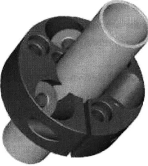
perpendicular pair of linkages (creating a five-bar closed chain linkage) to directly control pitch and yaw. The first of these, the Immersion Impulse Engine, uses a linear capstan drive with a cable running the length of the tool in order to actuate the insertion axis (Rosenberg, 1996). The Bleuler Lab at the Ecole Polytechnique developed a similar device, and have designed a crossed-roller bearing structure which supports both the linear and rotational of motion using pairs of opposing rollers angled at +/- 45 degrees from the tool shaft. This configuration is shown in Figure 3-2.
Figure 3-2. Combined bearing to support linear and rotational motion of the tool shaft developed by the Bleuler Lab (Vollenweider, 1999).
Limited information was available about this device, but it was understood that when the tool is moved in pure insertion the rollers turn in the same direction, and when the motion is pure rotation, the rollers turn opposite one another. These axes are apparently not actuated, but it is conceivable to design active degrees of freedom on this principle (Vollenweider, 1999).
The next pair of devices are again closed-chain linkages which make use of two slotted links to support the pitch and yaw axes. The first of these, developed by Forschungszentrum
Karlsruhe (FZ Karlsruhe) is actually not a force-feedback device but rather a passive position input device bearing a kinematic configuration similar to that found in some joysticks; again, it is plausible to consider an actuated version of this device. In this design, the tool passes through the crossing point of the two curved, slotted links, thus dictating the position of the tool within a semispherical workspace around the pivot at the intersection of these axes (Krumm, 1999). The second device was made by the University of Hull VEGA group and uses a slightly different method: the center of curvature of one curved link is coincident with the center of a straight link to which the pivot of the tool is affixed. Here, sliding contact is made with only the curved link. This device does not include an insertion degree of freedom (University of Hull, 1999).
Finally, the Hauptabteilung Ingenieurtechnik (HIT) device (5) could be found only as a rendered model on the FZ Karlsruhe webpage, but from this rendition can be described as an open-chain serial manipulator (Krumm, 1999).
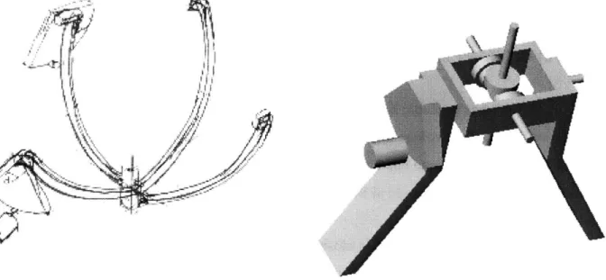
Taken together, this collection of previous work constituted a very comprehensive examination of the design options for these axes. Still, a couple of concepts were generated, including one inspired by the structure of the FZ Karlsruhe device and a differential-based device are shown in Figure 3-3.
Figure 3-3. Concepts generated in brainstorming.
The first of these was essentially an inverted version of the FZ Karlsruhe input device in which the slotted links were replaced by rails on which rolling element bearings could be mounted. In the second design, a first motor would pitch a second stage which supported a cable differential capable of providing yaw and rotation feedback in parallel. Actuation for the linear insertion motion could be added to either of these using a linear capstan or crossed rollers.