Science Arts & Métiers (SAM)
is an open access repository that collects the work of Arts et Métiers Institute of Technology researchers and makes it freely available over the web where possible.
This is an author-deposited version published in: https://sam.ensam.eu
Handle ID: .http://hdl.handle.net/10985/16558
To cite this version :
Aude BOUDELIER, Mathieu RITOU, Sébastien GARNIER, Benoit FURET - Cutting force model for machining of CFRP laminate with diamond abrasive cutter - Production Engineering - Vol. 12, n°2, p.279-287 - 2018
Any correspondence concerning this service should be sent to the repository Administrator : archiveouverte@ensam.eu
https://doi.org/10.1007/s11740-018-0813-4
Cutting force model for machining of CFRP laminatewith diamond
abrasive cutter
A. Boudelier1,2 · M. Ritou1 · S. Garnier1 · B. Furet1
Abstract
The article presents a cutting force model for trimming operations of CFRP laminate with diamond abrasive cutters. Those tools are more and more encountered on industrial applications of CFRP trimming, due to their abrasion resistance and their low cost. Contrary to endmills, they consist of a large number of cutting grits, randomly distributed around the tool. To tackle the issue, a continuous model of tool engagement is proposed. Validity of the approach is verified. A mechanical model of cutting forces, adapted to CFRP laminate, is then presented. The evolution of specific cutting coefficient in relation to fibres orientation is investigated through a piecewise constant model. It leads to the proposal of a sine model for the specific cut‑ ting coefficients. The simulated forces are in good agreement with the experimental results of cutting tests, carried out in multidirectional CFRP laminate for different fibres orientation and widths of cut. Cutting mechanisms are finally discussed depending on fibres orientation.
Keywords Cutting force model · Composite · Trimming · Multidirectional CFRP laminate · Diamond abrasive cutter · Cutting mechanism
1 Introduction
Machining of composite laminates is often difficult because of their mechanical and thermal properties: heterogeneity, anisotropy and low thermal conductivity [18]. Moreover, their high abrasiveness, notably mentioned by Ramkumar et al. [13] in drilling operations and Dumas et al. [7] in mill‑ ing operations, conducts to premature tool wear. That is why diamond abrasive cutters, constituted of small diamond grits (Fig. 1), have been specifically developed for CFRP trim‑ ming operations. In comparison with carbide or polycrys‑ talline diamond tools (PCD), tool life and productivity are improved while material integrity is respected. Moreover, costs are reduced.
Very few studies concern diamond abrasive cutters. Collingan and Ramulu [6] characterised trimmed sur‑ faces depending on tool grits size and feedrate. They also
performed preliminary tests to study influence of these parameters on cutting forces. Boudelier et al. [5] studied the CFRP machinability with diamond abrasive cutters. However, no cutting force model has been proposed for this tool technology whereas it is necessary in order to optimize cutting conditions and avoid material integrity defects.
Slamani et al. [15] studied the cutting force during the robotized trimming of CFRP. Force models have been pro‑ posed for orthogonal cutting with carbide [2] and PCD tools Wang et al. [12, 19]. Influence of fibres orientation, feed rate and cutting speed has essentially been studied. Empirical [20], numerical [1, 10, 14] and analytical models have been developed. The latter are based on a tangential—radial cut‑ ting force approach. At a macroscopic scale, the influence of fibres orientation can be integrated into the specific cut‑ ting coefficients through sine [3, 8, 16] or polynomial mod‑ els [17]. At a microscopic scale, approaches based on the chip formation were developed, considering fibres breaking mechanisms [2, 11, 22]. Also, Yuan [21] proposed a force model for the ultrasonic machining of CFRP.
In this paper, an analytical model of cutting force for trimming operations of multidirectionnal CFRP laminate with diamond abrasive cutters is presented. Contrary to end‑ mills, diamond cutters consist of a multitude of grits with
* M. Ritou
mathieu.ritou@univ‑nantes.fr
1 LS2N (Laboratory of Digital Sciences of Nantes, UMR
CNRS 6004), Universite de Nantes, 44035 Nantes, France
2 Laboratoire Arts et Metiers ParisTech d’Angers (LAMPA),
irregular shapes that are randomly distributed around the tool [9]. That is why a continuous model of tool engagement is proposed. Secondly, as the influence of fibres orientation on the specific cutting coefficients is unknown, a first inves‑ tigation is carried out based on a piecewise constant model. The results lead to the proposition of a sine model of specific cutting coefficients. Then, accuracy of the model is evalu‑ ated and compared to experiments carried out over the entire range of fibres orientation (− 90° to + 90°). Finally, results of the model are expressed in the fibres reference system in order to discuss cutting mechanisms depending on fibres orientation.
2 Tool engagement models
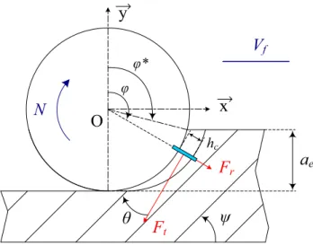
2.1 Cutting edge modelClassical milling cutters rely on a given number of cutting edges. Tool engagement is modelled by localized engage‑ ments of cutting edges. Then, cutting forces generated by each cutting edge during material removal are proportional to chip thickness. Tangential and radial forces, applied by tool on material, are respectively defined by the following expressions:
where Kt and Kr are the tangential and radial specific cutting coefficients (MPa), fz is the feed per tooth (mm/rev/tooth), ap the depth of cut (mm), φ the tooth angular position.
In the case of machining of CFRP laminates, the spe‑ cific cutting coefficients vary with fibre orientation θ that corresponds to the angle between cutting speed direction (1)
Ft(𝜑) = Kt(𝜃) ⋅ fz⋅ sin(𝜑).ap
Fr(𝜑) = Kr(𝜃) ⋅ fz⋅ sin(𝜑).ap
and fibre orientation of the considered unidirectional ply in the laminate (Fig. 2). During tool revolutions, it evolves with the tool angular position.
2.2 Continuous model of tool engagement
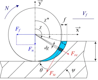
Considering trimming operations with diamond abrasive cutters, cutting models must be adapted. Indeed, a dia‑ mond abrasive cutter is close to a grinding tool but with a larger grit size. Contrary to tools with cutting edges, it relies on a large number of grits, with a random distribu‑ tion of height and position around the tool body (Fig. 1). From one tool to another, the distribution is different. Contrary to endmills, multiplicity and randomness of cut‑ ting grits lead to constant cutting forces during machin‑ ing. Consequently, the classical approach with a localized engagement of each cutting edge is not appropriated.
The assumption is made that the grits distribution around the tool is homogenous and uniform. This is the reason why a continuous tool engagement model is pro‑ posed in the paper. At each instant, it is considered that the diamond abrasive cutter generates cutting forces all along the tool engagement domain. The domain is discretized into elementary sectors dχ (Fig. 3). In order to obtain the elementary tangential Fte (χ) and radial Fre (χ) forces for each elementary sector dχ, angular specific cutting coef‑ ficients Kt (θ)/2π and Kr (θ)/2π must be introduced:
where f is the feed per revolution (mm/rev).
(2)
Fte(𝜒) =Kt(𝜃)
2 ⋅ 𝜋 ⋅ f ⋅ ap⋅ sin(𝜒 )
Fre(𝜒) = Kr(𝜃)
2 ⋅ 𝜋 ⋅ f ⋅ ap⋅ sin(𝜒 )
Fig. 1 Diamond abrasive cutter with grits size of 852 µm
N
a
eV
fψ
θ
x
y
φF
rF
t hc φ*O
2.3 Coherence between the two approaches
The objective of the paragraph is to demonstrate that Kt (θ), which has been introduced in the expression of elementary tangential force with diamond abrasive cutter approach (Eq. 2), is similar to the one considered with endmills (Eq. 1). To do so, the mechanical works of the spindle dur‑ ing a revolution are compared for the two tool engagement approaches.
In case of machining with endmills, the spindle work Wc during one tool revolution is the sum of the work of each cutting edge j. It can be obtained by summing the instantane‑ ous spindle power during one tool revolution period:
where T is the tool revolution period, Vc the tool cutting speed and R the tool radius. Considering that Vc=R.dφ/dt, and introducing Eq. [1] in (3), the spindle work can be expressed as:
In case of machining with diamond abrasive cutter, the instantaneous spindle power Pd resulting from the elemen‑ tary tangential forces Fte (χ) can be expressed as:
From Eq. [2], it follows that:
(3) Wc= Z ∑ j=1 T ∫ 0 Vc⋅ Ft⋅ dt (4) Wc= R ⋅ f ⋅ ap⋅ 𝜋 ∫ 𝜑∗ Kt(𝜃) ⋅ sin(𝜑) ⋅ d𝜑 (5) Pd= 𝜋 ∫ 𝜒∗ Vc⋅ Fte(𝜒) ⋅ d𝜒
As the tool is considered as continuously engaged (Fig. 3), the spindle power is constant. Thus, the spindle work for abrasive cutter Wd is simply given by:
As the period T = 2πR/Vc, the work can be written as:
The analytical expressions of the spindle work (Eqs. 4 and 8) are identical for the two tool engagement models. Consequently, the specific cutting coefficients that will be identified in the paper can be compared with ones obtained for other cutting tool technologies.
3 Cutting force model for multidirectional
laminate
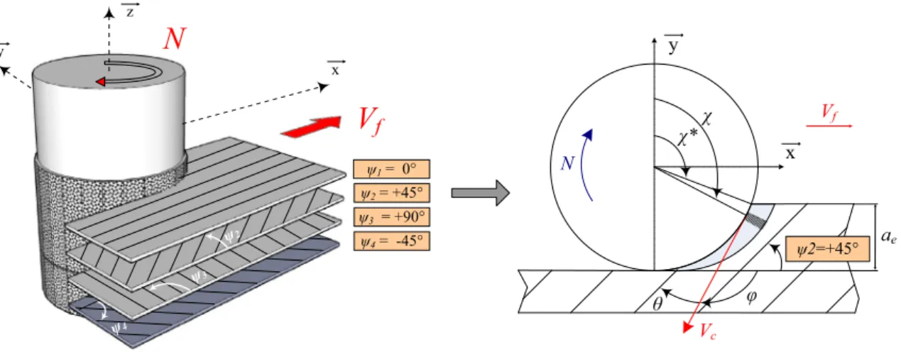
The CFRP multidirectional laminates of aeronautic struc‑ ture consist in a stack of plies with, generally, unidirectional carbon fibres (see Fig. 4); according to the laminate lay‑up that defines the sequence of ply orientations (see lay‑up in Table 1). ψ represents the fibre orientation of a given ply, in relation to feed direction.
Let’s consider the machining of a given ply with a dia‑ mond abrasive cutter, the local depth of cut corresponds to the ply thickness e. The feed force Ff (ψ) and the normal force Fn (ψ) can be obtained by summing the elementary forces along the tool engagement domain. After projection in the feed reference system (x,y), they can be expressed by the following expressions:
where ψ represents the fibre orientation in relation to feed direction. θ is the relative orientation between fibre and cut‑ ting direction:
In order to determine the average cutting forces gener‑ ated during the trimming of a multidirectional laminate, a mixture approach is used [16, 1720]. It assumes that the (6) Pd = Vc⋅ f ⋅ ap⋅ 𝜋 ∫ 𝜒∗ Kt(𝜃) 2.𝜋 ⋅ sin(𝜒 ) ⋅ d𝜒 (7) Wd= T ∫ 0 Pd⋅ dt = Pd⋅ T (8) Wd= R ⋅ f ⋅ ap 𝜋 ∫ 𝜒∗ Kt(𝜃) ⋅ sin(𝜒) ⋅ d𝜒 (9) [ Ff(𝜓) Fn(𝜓) ] = f 2.𝜋⋅ e ⋅∫ 𝜋 𝜒∗ sin(𝜒) ⋅ [ cos 𝜒 sin 𝜒 − sin 𝜒 cos 𝜒 ] ⋅ [ Kt(𝜃) Kr(𝜃) ] ⋅ d𝜒 (10) 𝜃= 𝜓 + 𝜒 𝜃 ∈ ]−𝜋∕ 2;𝜋∕ 2]
N
a
eV
fψ
θ
x
y
χF
reF
te χ* dχf
F
nF
finteractions between plies are neglected. Indeed, the inter‑ face between two plies is only composed of polymer matrix. Its mechanical behaviour during trimming is negligible in comparison with plies one’s. This hypothesis will be vali‑ dated in a following section. Consequently, the cutting forces can be simply obtained by summing the forces necessary to machine each unidirectional ply of the laminate (Fig. 4):
where m is the number of different ply orientations, nψi the number of ply oriented at an angle of ψi degrees and ei the ply thickness, for a given orientation i.
4 Model of specific cutting coefficients
At this step of the study, the evolution of the specific cutting coefficients in relation to the relative fibre orientation θ is unknown. This is the reason why the expression of Kt (θ) (11) [ Ff Fn ] = f 2 ⋅ 𝜋 ⋅ m ∑ i=1 n𝜓i⋅ ei⋅∫ 𝜋 𝜒∗ sin(𝜒) ⋅ [ cos 𝜒 sin 𝜒 − sin 𝜒 cos 𝜒 ] ⋅ [ Kt(𝜃) Kr(𝜃) ] ⋅ d𝜒
and Kr (θ) are, in a first approach, modelled by a piecewise constant function in order to observe their evolution. 4.1 Investigation of the influence of fibres
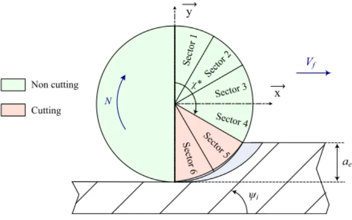
orientation on specific cutting coefficients The relative fibre orientation θ varies from − π/2 to + π/2. It is divided into nz different sectors of βz degrees. The specific cutting coefficients Kt (θ) and Kr (θ) are assumed constant for each sector. As the feed direction and the ply orientation
ψ remain identical during the cutting tests, the relative fibre
orientation θ also remains identical considering a given sec‑ tor of the tool (Fig. 5).
Consequently, the tangential and radial specific cutting coefficients are considered constant for each sector of the tool. Hence, only tool sectors will be considered. In this way, the feed force can be expressed as:
(12) Ff= f 2.𝜋 ⋅ m ∑ i=1 n𝜓i⋅ ei⋅ [ n z ∑ j=nze Kt(𝜃i j)⋅ ∫ j⋅𝛽z (j−1)⋅𝛽z sin(𝜒) ⋅ cos(𝜒) ⋅ d𝜒 + nz ∑ j=nze Kr(𝜃i j) ⋅ ∫ j⋅𝛽z (j−1)⋅𝛽z sin2(𝜒) ⋅ d𝜒 ] ψ1= 0° ψ4= -45° ψ3= +90° ψ2= +45°
V
fN
N ae x y χ* Vf ψ2 ψ3 ψ4 x z y θ Vc ψ2=+45° φ χFig. 4 Example of configuration of a multidirectional laminate, composed of m = 4 plies with unidirectional fibres Table 1 Mechanical properties
of carbon/epoxy material T800‑M21 (Hexcel)
Number of plies 37
Ply thickness 0.27 mm
Fibre volume fraction 56.6%
Laminate Density Compression modulus Tensile modulus 1580 kg/m3 136 GPa 172 GPa Lay up (90/− 45/0/45/0/45/0/− 45/0/0/0/0/− 45/90/90/45/0/90/ 90/0/45/90/− 45/90/− 45/0/0/0/0/− 45/0/45/0/45/0/− 45/90)
where θij is the relative fibre orientation of an angular sec‑ tor j, for a ply orientation i; and nze is the index of the first cutting sector of the tool, evaluated by the floor function of
nz.χ*/π + 1.
In this way, the Feed and Normal force models lead to a linear combination of the specific cutting coefficients, which will simplify their identification. Since the radial and tangential specific cutting coefficients are represented by a piecewise constant function, Eq. [12] can be expressed as a matrix product of the specific cutting coefficients K:
where ncut is the number of cutting tests. Therefore, the specific cutting coefficients can be identified by matrix inver‑ sion: K = A− 1.F.
4.2 Experimental setup
An aeronautic CFRP laminate of T800‑M21 was trimmed to carry out the experiments. The laminate was composed of 37 plies of unidirectional graphite fibre fabric, made by alternating four fibres orientations (Table 1). The matrix used was a thermosetting epoxy resin M21.
The diamond abrasive cutter used during the experiments was composed of natural diamond grits fixed with a nickel bond on a cylindrical body by electro deposition (Fig. 1). A 16 mm tool diameter with 852 µm grits size was used. Widths of cut of 16 mm (slot) and 5.94 mm (in down‑mill‑ ing) were machined. For a discretization of the tool engage‑ ment in 12 sectors (nz=12) in the piecewise model (Fig. 5), these two widths of cut have solicited respectively 12 (χ*=0°) or 5 tool sectors (χ*=105°). For each width of cut, 12 machining directions from ψ = 0° to 180° were studied.
Trimming tests were carried out on a three‑axis Huron KX30 milling machine, equipped with a 28,000 RPM − 40 kW Kessler spindle. Cutting forces were measured using a 9255B (13) F= A.K with F= [ Ff Fn ] 2ncut,1 , K= [ Kt Kr ] 2nz, 1 and A2ncut,2nz
Kistler three‑component dynamometer. It was mounted between the workpiece and the table of the machining cen‑ tre. Contrary to endmills, diamond abrasive cutters lead to constant cutting forces during cuts. So, for each run, average values of feed force Ff and normal force Fn are evaluated and resultant of cutting forces F is calculated.
All the experiments were carried out with external and internal water‑based coolant, and industrial HSM cutting con‑ ditions were used, as defined in Table 2.
4.3 Results of the investigation
The specific cutting coefficients of the piecewise model have been identified by matrix inversion (Eq. 12) and based on the feed forces Ff and normal forces Fn of the ncut =24 cuts of the experiments. Results are illustrated in Fig. 6.
Experimental results show that the mean value of tangen‑ tial specific cutting coefficient is 1050 MPa and mean radial coefficient is 2360 MPa. Moreover, it is shown that fibres ori‑ entation significantly affects the specific cutting coefficients, and consequently on cutting forces. Indeed, variations around the average values are important. Tangential coefficient varies from 80 to 1780 MPa and radial coefficient varies from 780 to 3680 MPa. That is why considering the fibres orientation in cutting force model is necessary.
However, a constant piecewise model is not robust and could lead to different shapes after identifications in relation to the noise in the experimental results. Consequently, based on the observations with the piecewise model, a simplified analytical model is proposed to describe the evolution of the specific cutting coefficients in relation to fibres orientation. 4.4 Specific cutting coefficients model
Due to the previous results (Fig. 6), an analytical model of the specific cutting coefficients in relation to fibres orientation is proposed: (14) Kt(𝜃) = Ktm+ Kta⋅ sin(2 ⋅ 𝜃 + 𝜓t) Kr(𝜃) = Krm+ Kra⋅ sin(2 ⋅ 𝜃 + 𝜓r) N ae ψi x y χ* Vf Sector 1 Sector 2 Sector 3 Sector 4 Sector 5 Sector 6 Non cutting Cutting
Fig. 5 Piecewise constant model
Table 2 Cutting conditions
Cutting speed 1400 m/min
Spindle speed 27,850 RPM
Feed per revolution 0.25 mm/rev
Depth of cut 9.96 mm
Widths of cut 16 and 5.94 mm
Machining direction − 75°, − 60°, − 45°, − 30°,
− 15°, 0°, 15°, 30°, 45°, 60°, 75°, 90°
where Ktm and Krm are the mean values, Kta and Kra their amplitude and ψt and ψr their phase angle. In accord‑ ance with previous investigation, a 2θ appears since θ is π‑periodic. Finally, the expressions of cutting forces (11) can be expressed as:
In order to simplify the identification of model param‑ eters, the model can be linearized:
Thus, Eq. [15] can be expressed as a linear combination of the parameters of specific cutting coefficient model:
It can be expressed as a matrix product:
with F is the matrix containing the experimental cutting forces of the ncut experiments, A the matrix representing chip sections, and K the matrix containing the specific cutting coefficients (a0,a1,a2,b0,b1,b2). These parameters (15) [ Ff Fn ] = f 2 ⋅ 𝜋 ⋅ m ∑ i=1 n𝜓 i⋅ ei⋅∫ 𝜋 𝜒∗ sin(𝜒) ⋅ [ cos 𝜒 sin 𝜒 − sin 𝜒 cos 𝜒 ] ⋅ [ Ktm+ Kta. sin(2.𝜃 + 𝜓t) Krm+ Kra. sin(2.𝜃 + 𝜓r) ] ⋅ d𝜒 (16) Kt(𝜃) = a0+ a1⋅ sin(2 ⋅ 𝜃) + a2⋅ cos(2 ⋅ 𝜃) Kr(𝜃) = b0+ b1⋅ sin(2 ⋅ 𝜃) + b2⋅ cos(2 ⋅ 𝜃) (17) with | | | | | | | a0= Ktm a1= Kta⋅ cos (𝜓t) a2= Kta⋅ sin (𝜓t) and | | | | | | | b0= Krm b1= Kra⋅ cos (𝜓r) b2= Kra⋅ sin (𝜓r) (18) Ff = f 2 ⋅ 𝜋 ⋅ m ∑ i=1 n𝜓i⋅ ei⋅ ( ao⋅ ∫ 𝜋 𝜒∗ sin(𝜒) ⋅ cos(𝜒) ⋅ d𝜒 + a1⋅ ∫ 𝜋 𝜒∗
sin(𝜒) ⋅ cos(𝜒) ⋅ sin(2 ⋅ 𝜃) ⋅ d𝜒
+ a2⋅∫ 𝜋
𝜒∗
sin(𝜒) ⋅ cos(𝜒) ⋅ cos(2 ⋅ 𝜃) ⋅ d𝜒 + bo⋅ ∫ 𝜋 𝜒∗ sin2(𝜒) ⋅ d𝜒 +b1⋅∫ 𝜋 𝜒∗ sin2(𝜒) ⋅ sin(2 ⋅ 𝜃) ⋅ d𝜒 + b2⋅ ∫ 𝜋 𝜒∗ sin2(𝜒) ⋅ cos(2 ⋅ 𝜃) ⋅ d𝜒 ) (19) F2n cut,1= A2ncut,6⋅ K6,1
of the analytical model can hence be identified by matrix inversion (Eq. 19).
5 Results
All the experiments presented in Table 2, i.e. 24 couples of feed/normal forces, have been considered in order to identify the parameters of the specific cutting coefficients model (Eq. 14) through matrix system inversion (Eq. 19). Results are presented in Table 3 and illustrated in Fig. 7.
Maximum tangential and radial specific cutting coef‑ ficients are obtained respectively for a fibre orientation of −54° and − 40° whereas their minimum corresponds to an orientation of 36° and 50°.
Considering the identified model of specific cutting coefficient, feed and normal forces have been calculated (Eq. 15). Simulated cutting forces are compared with experiments in Fig. 8.
The prediction of feed and normal forces is in accord‑ ance with the experimental data. The relative errors are respectively estimated at ± 7.8% and ± 5.8% (or ± 39 N and ± 24 N) for machining operation with a low width of
Fig. 6 Evolution of the specific cutting coefficients. a Kt(θ) and b Kr(θ) identified through a piecewise constant model
-900 -60 -30 0 30 60 90 500 1000 1500 2000 2500 3000 3500 4000 φr (deg) Kt ( θ) (MPa ) -900 -60 -30 0 30 60 90 500 1000 1500 2000 2500 3000 3500 4000 θr (deg) Kr (θ ) (MPa ) ψ (deg) ψ nz=12 βz=15° average a nz=12 b βz=15° average Kt (θ) (Mpa) Kr (θ) (Mpa) θ (deg) θ (deg)
Table 3 Identified parameters of the specific cutting coefficient model
Ktm 1053.7 MPa Krm 2361.5 MPa
Kta 189.8 MPa Kra 1082.2 MPa
cut (5.94 mm) whereas they are evaluated at ± 3.2% and ± 6.1% (± 46 N and ± 39 N) for a 16 mm tool engagement.
6 Discussion
First point of discussion concerns the levels of specific cut‑ ting coefficients. During machining with diamond abra‑ sive cutters, and contrary to machining with endmills, the radial component is more important than the tangential one
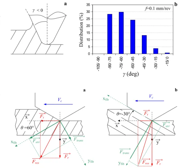
(Fig. 7). Tool geometry explains this trend. Indeed, rake angles are generally positive for milling with carbide or PCD tools (from 0 to 18°) [2, 19]. Consequently, cutting configuration is favourable and specific cutting coefficients associated to the couple Tool/Material are low. During machining operation with diamond abrasive cutters, cutting is less efficient. Indeed, the rake angles are highly negatives because grits have rather a spherical shape. By tool scan‑ ning, Boudelier et al. [4] established that the average rake angle is ‑65° (Fig. 9). Consequently, level of specific cutting coefficients is higher.
In order to explain the influence of fibres orientation on the variations of specific cutting coefficients, results have been transposed to an orthogonal cutting configuration (Fig. 10). The grit is represented with the average rake angle. A chip section of 1 mm2 has been considered (f = 0.1 mm/ rev, ap=10 mm). Tangential Ft, radial Fr and resultant Fres forces have been simulated depending on fibres orientation, using the previously identified parameters (Table 3). Then, the resultant force Fres have been projected onto the fibres reference system (xfib; yfib). Two components are obtained:
Faxi oriented in the fibres direction and Ftrans orthogonal to the fibres (Fig. 10). Results are shown in the Fig. 11.
Firstly, the lowest resultant force is obtained for a fibers orientation of about 60°. In that case, the grit cutting face is nearly perpendicular to fibres axis (Fig. 10a). Transverse force
Ftrans is negligible and only an axial force Faxi is generated
Fig. 7 Analytical model of the specific cutting coefficients in relation to fibre orientation, a Kt(θ) and b Kr(θ), identified from the experi‑ ments
Fig. 8 Experimental and simu‑ lated feed forces Ff (a–c) and
normal forces Fn (b–d), ae =
16 mm (a–b) and ae = 5.94 mm
(Fig. 11). A compressive load is applied along fibres direction and a significant shear at the fibre–matrix interface appears. It is very favourable to crack initiation and propagation. Indeed, the fibre–matrix interface is considered as the weak point of polymer matrix composites due to their low interlaminar shear strength [17]. As resultant force is minimal, this configuration of fibres orientation is optimum for cutting operation.
The highest resultant force is obtained for fibres orienta‑ tion around − 30°. In that case, the grit cutting face is nearly parallel to fibres axis (Fig. 10b). In this configuration, a signifi‑ cant transverse force Ftrans is generated, perpendicularly to the grit cutting face. Fibers are compressed the one on the other. Besides, axial force Faxi applied on fibres is very low. That leads to very low shear at the fibre–matrix interface. As the weakness of the material is lowly solicited, this configuration is unfavorable for the cut.
7 Conclusions
A cutting force model dedicated to the machining of multidi‑ rectional CFRP laminate with diamond abrasive cutters was proposed. The analytical approach is based on the variation of specific cutting coefficients depending on fibres orienta‑ tion. The following conclusions can be drawn:
1. The model allows accurate prediction of cutting forces during trimming of multidirectional CFRP with dia‑ mond abrasive tools, over the entire range of fibres ori‑
Fig. 9 a Definition of grits rake angle, b Distribution of grits rake angle on a diamond abra‑ sive cutter (grits size of 852 µm)
f= 0.1 mm/ tr 0 5 10 15 20 25 30 35 -1 05 /-90 -9 0/ -7 5 -7 5/ -6 0 -6 0/ -4 5 -4 5/ -3 0 -3 0/ -1 5 -1 5/ 0 γ < 0
a
b
γ (deg)
Distribution (%) f=0.1 mm/revFig. 10 Cutting forces projec‑ tion onto fibres reference system
Vc Ft Fr Ftrans Faxi Vc y x θ=-30° Ftrans y x θ =60° Ft Fr xfib
yfib yfib Fres
xfib
b a
Faxi Fres
entation (− 90° to + 90°) and for different widths of cut. Indeed, the simulated forces were in good agreement with the experimental results. Model error was evaluated at ± 7.8% for feed force and ± 5.8% for normal force. 2. An original approach was proposed in order to consider
the large number of grits that are randomly distributed around the tool. Conversely to the local engagement of endmill cutting edge, a continuous engagement of the tool was introduced. Coherence with endmill model was verified. This approach represents a significant improve‑ ment over previous models and could be extended to grinding applications.
3. Variations of specific cutting coefficients depending on fibres orientation were investigated using a piecewise constant model. It led to the proposal of a sine model for the specific cutting coefficients. Combined with a mixture approach, accurate prediction of cutting forces during trimming operation of multidirectional laminate was obtained.
4. Results of the model were transposed to an orthogonal cutting operation and cutting forces were expressed in the fibres reference system. Cutting mechanisms were then discussed depending on fibres orientation in order to explain the variation of specific cutting coefficients.
Acknowledgements This work was carried out within the context of the working group Manufacturing’21 which gathers 16 French research laboratories. The topics approached are: modelling of the manufactur‑ ing processes, virtual machining, and emergence of new manufacturing methods.
References
1. Arola D, Sultan MB, Ramulu M (2002) Finite element modeling of edge trimming fiber reinforced plastics. J Manufac Sc Eng Trans ASME 124(1):32–41
2. Bhatnagar N, Ramakrishnan N, Kaik NK, Komanduri R (1995) On the machining of fiber reinforced plastic (FRP) composite laminates. Int J Mach Tools Manuf 35(5):701–716
3. Bonnet C, Benmohammed B, Poulachon G, Rech J, Girard Y (2011) CFRP drilling model: fiber orientation influence on mechanical load and delamination. Adv Mater Res 223:111–121 4. Boudelier A, Ritou M, Garnier S, Furet B (2011) Optimisation of process parameters in cfrp machining with diamond abrasive cutters. Adv Mater Res 223: 774–783. https ://doi.org/10.4028/ www.scien tific .net/AMR.223.774
5. Boudelier A, Ritou M, Garnier S, Furet B. (2013) Investigation of CFRP machining with diamond abrasive cutters. Revue des
Composites et des Matériaux Avancés 23(3):425–436. https ://doi. org/10.3166/RCMA.23.425‑436
6. Collingan K, Ramulu M (1999) Edge trimming of graphite/epoxy with diamond abrasive cutters. J Manuf Sci Eng 121:647–655.
https ://doi.org/10.1115/1.28330 89
7. Dumas C, Boudelier A, Caro S, Garnier S, Ritou M, Furet B (2011) Development of a robotic cell for trimming of compos‑ ite parts. Mech Indus 12(6):487–494. https ://doi.org/10.1051/ meca/20111 03
8. Karpat Y, Bahtiyar O, Deger B (2012) Mechanistic force model‑ ling for milling of unidirectionnal carbon fiber reinforced poly‑ mer laminates. Int J Mach Tools Manuf 56:79–93. https ://doi. org/10.1016/j.ijmac htool s.2012.01.001
9. Malkin SK (1989) Grinding technology: theory and applications of machining with abrasives. Ellis Horwood Limited, Chister 10. Nayak D, Bhatnagar N, Mahajan P (2005) Machining studies of
UD‑GFRP composites part 2: finite element analysis. Mach Sci Technol 9(4):503–528
11. Puw HY, Hocheng H (1998) Chip formation model of cutting fiber‑reinforced plastics perpendicular to fiber axis. Trans ASME 120:104–114
12. Ramulu M (1997) Machining and surface integrity of fibre‑rein‑ forced plastic composites. Sadhana 22(3):449–472
13. Ramkumar J, Malhotra SK, Krishnamurthy R (2004) Effect of workpiece vibration on drilling of GFRP laminates. J Mater Pro‑ cess Technol 152:329–332
14. Venu Gopala Rao G, Mahajan P, Bhatnagar N (2008) Three‑ dimensional macro‑mechanical finite element model for machin‑ ing of unidirectional‑fiber reinforced polymer composites. Mater Sci Eng 498:142–149
15. Mohamed Slamani S, Gauthier J‑F, Chatelain (2015) A study of the combined effects of machining parameters on cutting force components during high speed robotic trimming of CFRPs. Measurement 59:268–283. https ://doi.org/10.1016/j.measu remen t.2014.09.052
16. Sheikh‑Ahmad J, Tworney J, Kalla D, Lodhia P (2007) Multiple regression and committee neural network force predition models in milling FRP. Mach Sci Technol 11(3):391–412
17. Sheikh‑Ahmad J (2009) Machining of polymer composites, Springer, New York
18. Teti R (2002) Machining of composite materials. CIRP Ann Manufac Technol 51:611–634
19. Wang DH, Ramulu M, Arola D (1995) Orthogonal cutting mecha‑ nisms of graphite/epoxy composite. Part I: unidirectional lami‑ nate. Int J Mach Tools Manuf 35:1623–1638
20. Wang DH, Ramulu M, Arola D (1995) Orthogonal cutting mech‑ anisms of graphite/epoxy composite. Part II: multi‑directional laminate. Int J Mach Tools Manuf 35(12):1639–1648
21. Yuan S, Zhang C, Amin M, Fan H, Liu M (2015) Development of a cutting force prediction model based on brittle fracture for carbon fiber reinforced polymers for rotary ultrasonic drilling. Int J Adv Manuf Technol. https ://doi.org/10.1007/s0017 0‑015‑7269‑x
22. Zhang LC, Zhang HJ, Xiang XM (2001) A force prediction model for cutting unidirectional fibre‑reinforced plastics. Mach Sci Tech‑ nol 5(3):293–305