Science Arts & Métiers (SAM)
is an open access repository that collects the work of Arts et Métiers Institute of Technology researchers and makes it freely available over the web where possible.
This is an author-deposited version published in: https://sam.ensam.eu
Handle ID: .http://hdl.handle.net/10985/12537
To cite this version :
Elise GRUHIER, Frédéric DEMOLY, Samuel GOMES - A spatiotemporal information management framework for product design and assembly process planning reconciliation -Computers in Industry - Vol. 90, p.17-41 - 2017
A spatiotemporal information management framework for
product design and assembly process planning
reconciliation
Abstract
This paper introduces an innovative framework for product design and assembly process planning reconciliation. Nowadays, both product lifecycle phases are quasi concurrently performed in industry and this configura-tion has led to competitive gains in efficiency and flexibility by improving designers’ awareness and product quality. Despite these efforts, some lim-itations/barriers are still encountered regarding the lack of dynamical rep-resentation, information consistency and information flow continuity. It is due to the inherent nature of the information created and managed in both phases and the lack of interoperability between the related information sys-tems. Product design and assembly process planning phases actually gener-ate heterogeneous information, since the first one describes all information related to “what to be delivered” and the latter rationalises all information with regards to “how to be”. In other words, the integration of assembly planning issue in product design requires reconciliation means with appro-priate relationships of the architectural product definition in space with its assembly sequence in terms of time. Therefore, the main objective is to provide a spatiotemporal information management framework based on a strong semantic and logical foundation in product lifecycle management (PLM) systems, increasing therefore actors’ awareness, flexibility and ef-ficiency with a better abstraction of the physical reality and appropriate information management procedures. A case study is presented to illustrate the relevance of the proposed framework and its hub-based implementation within PLM systems.
Keywords: Product Lifecycle Management, Ontology, Mereotopology,
Assembly oriented design, Product architecture, Assembly planning, Reconciliation
Contents
1 Introduction 2
2 Heterogeneity management issues in engineering 5
3 Research background: Theory, ontology and approach 8
3.1 JANUS as a spatiotemporal mereotopology-based theory . . . 8
3.2 PRONOIA2 as a spatiotemporal ontology . . . 10
3.3 PROMA as an integrated management approach . . . 12
3.4 Motivation . . . 13
4 Spatiotemporal information management framework 14
4.1 Management of product-process information consistency . . . 16
4.2 Information flow through PLM . . . 20
4.3 Representation of design and assembly evolutions within a
CAD application . . . 31
5 Case study in a drones-based application 34
5.1 Case study: Drones-based design for medical emergency . . . 34
5.2 MERCURY deployment regarding assembly evolution . . . . 36
5.3 MERCURY deployment regarding design evolution . . . 45
6 Discussions 49
7 Conclusions and future work 50
1. Introduction
Over the last two decades, manufacturing industry has been progres-sively forced to compact its product lifecycles by ensuring a certain level of flexibility and efficiency as competitive edges, especially in the product de-velopment phase where design activities and decisions have a great impact on downstream processes. This has been done by considering the capture and integration of lifecycle constraints and knowledge in product design so as to deliver lifecycle friendly products. Nowadays, product design and assembly planning phases are almost concurrently processed in industry. This means that such effort has anyway provided competitive advantages in efficiency and flexibility by improving designers’ awareness and product quality. De-spite these efforts, some limitations are still encountered in product design regarding the lack of dynamical representation, information consistency and
Nomenclature
PLM Product Lifecycle Management
PDM Product Data Management
MPM Manufacturing Process Management
CAD Computer-Aided Design
ASP Assembly Sequence Planning
ASDA Assembly Sequence Definition Algorithm
AOD Assembly Oriented Design
JANUS Joined AwareNess and Understanding in
assembly-oriented deSign with mereotopology
PROMA Product RelatiOnships Management Approach
PRONOIA2 PROduct relatioNships description based On
mereotopologIcAl theory 2
MUVOA MUlti-Views Oriented Assembly
MERCURY a ManagEment framework appRoaCh of prodUct and
process Relationships in assemblY and design phases
ASDA Assembly Sequence Definition Algorithm
BOM Bill Of Material
eBOM engineering Bill Of Material
mBOM manufacturing Bill Of Material
BOR Bill Of Relation
DMU Digital Mock-Up
GIS Geographical Information System
OWL Ontology Web Language
SWRL Semantic Web Rule Language
XML eXtensive Markup Language
information flow continuity. This is due to the inherent nature of the infor-mation created and managed in both phases and the lack of interoperability between the related information systems.
Product design and assembly planning phases actually generate hetero-geneous information. Indeed product design addresses the description of all information aligned to “what to be delivered”, while assembly process planning focuses on the definition of all information related to “how to be assembled”. In other words, the integration of assembly planning issue in product design requires reconciliation means with appropriate relationships of the architectural product definition in space with its assembly sequence in terms of time. The entire understanding of how parts are assembled
within the embodiment design process is a critical issue and hence requires an appropriate context associated to assembly oriented design (AOD) issue. Actually the architectural definition of the product over the design process is defined by aggregating numerous design decisions/changes and multiple assembly constraints, which are generally triggered by either product ar-chitect or the designer, or better yet by the assembly planner in the AOD context.
From an information system point of view, product design and assembly process become more and more knowledge-intensive and therefore demand adapted and intelligent environment able to ensure dynamical representa-tion, information consistency and information flow continuity in PLM sys-tems. Currently, multiple PLM systems covers the beginning of the product lifecycle, such as product data management (PDM), manufacturing process management (MPM) and computer aided design (CAD) systems to name a few. Such systems have been introduced to ensure the management of the entire digital mock-up (DMU) of the product including its data structure and geometric definition, and its related manufacturing and assembly pro-cesses. As a result, some interoperability issues remain to be tackled since such systems consider spatial and temporal information without appropri-ate semantic and logical relationships [32]. Moreover, the fact of considering such heterogeneous points of view about the product development generally leads to inconsistencies, multiple design iterations and a lack of information continuity [49, 51]. This operational challenge is emphasised by considering the proactive nature of assembly oriented design philosophy, which leads to propose a specific orchestration of the product-process information flows including appropriate viewpoints.
Some similar issues exist in the domains of geographic information sys-tem (GIS) and building information modelling (BIM), where ontology model is commonly considered as a solution to solve heterogeneity issues [27]. As such, one promising way to overcome this limitation is to introduce semantic and logical layers to product architecture definition via a multi-layer ontol-ogy [12]. Built on this, PRONOIA2 (PROduct relatioNships description based On mereotopologIcAl theory 2) ontology has been developed and will be considered as a foundational basis for the proposed framework. The on-tology will provide a useful bridge in order to connect current PDM, MPM and CAD data models and ensure information flow continuity and orches-tration.
As a consequence, this paper focuses on product design and assembly planning reconciliation in the context of AOD, which intends to consider as-sembly process planning issue in the embodiment design stage in a proactive
manner. Here the main objective is to provide a spatiotemporal information management framework based on a strong semantic and logical foundation in PLM systems, increasing therefore actors’ awareness, flexibility and ef-ficiency with a better abstraction of the physical reality and appropriate information management procedures. In this context, the entire and seam-less integration of assembly planning in product design has to be ensured with consistent relationships in the embodiment design phase to ensure a reliable product definition [29].
Firstly, the paper presents a brief literature survey on heterogeneity man-agement issues in product design and assembly planning. Then, in section 3, research background introduces the JANUS (Joined AwareNess and Un-derstanding in assembly-oriented deSign with mereotopology) theory based on mereotopology, the PRONOIA2 ontology, and the product relationships management approach (PROMA), considered here as the foundation of the proposed framework. Section 4 presents the core of the contribution with a spatiotemporal information management framework so as to manage prod-uct evolution from a design and assembly points of view. In section 5, a case study based on drones’ design is described in order to illustrate the relevance of the proposed framework and its hub-based implementation within PLM systems. Finally, the advantages and limits of the framework are discussed in section 6, and conclusions and future work are given.
2. Heterogeneity management issues in engineering
Some research issues remain to be tackled in PLM systems and more especially in PDM and MPM systems [28], where critical information is still lacking in order to have a full understanding of the design and process activ-ities. As an example, PDM systems currently manage purely spatial prod-uct information embedded in documents with various functionalities such as versioning, bill of material (BOM) management, workflow management, check-in/check-out procedures, change and configuration management and so on [21]. It intends to ensure that the right information is available for the right person at the right time and in the right format. Despite the in-formation brought by PDM systems, few even none inin-formation about the relationships between parts and changes undergone by the product during its development is captured and managed. For instance, some comments on product documents’ iterations enable the understanding of what has been changed between the different versions of a file, but a lack of semantic de-scription of changes in such systems is highlighted. Besides, MPM systems
are restricted to manage temporal information. The description of relation-ships between assembly operations are actually limited to precedence and equal relationships [31].
The current issue of PDM and MPM systems in industry is their uni-directional way of reconciliation, which leads to inconsistent product defi-nition over space and time, especially if a concurrent engineering strategy is adopted. Indeed, such procedure exists in MPM systems and enables a kind of continuity of product-process information via the engineering BOM (eBOM) and manufacturing BOM (mBOM) reconciliation link, but limited to a structural level. At this stage, it is vital to work at an architectural level, enabling the link of product and process models in the spatiotemporal dimension in order to better represent real phenomena, otherwise the lack of information about product evolution will be propagated on CAD models with a static description of the product. David and Rowe [6] went beyond such barrier and emphasised that PLM systems need a complex ontological model to process and integrate such information diversity. An effort to a sin-gle integrated system linking PLM systems in order to avoid heterogeneity issues has also been studied in [15].
Regarding information consistency in design engineering, Louhichi and Rivest [26] focused their efforts to maintain consistency between CAD work packages and the global product DMU . The same authors aim to control the DMU evolution, as well as the modification undergone. In addition, Chen and Luo [4] have made consistent the information travelling from de-sign to construction phases. The benefits of such an approach are to get a better visualisation and coordination of architecture, engineering and con-struction with less mistakes and omissions, therefore improving the produc-tivity and support for scheduling. Heterogeneity management is a recurrent
issue, which is encountered in many engineering projects. For instance,
BIM has attempted to manage spatial and temporal information. Spatial (i.e. building) and temporal (i.e. construction activities) information is sup-ported during the development process of a construction project [24]. BIM also aids stakeholders to schedule activities and manage changes during the project [36]. A planning is generally placed on top of current design tools in the form of a time sequence. So the model is constructed with the following data structure: product, organisation and process. Contrary to the spatial and temporal information, here spatiotemporal dimension is not covered.
In the context of GIS, Straume [48] works with land management tools so as to have a consistent description over space and time. As such, land changes over time can be identified and team partners can collaborate.
interoperabil-ity, which is the ability of a system to share information with other system. Similar works, developed by Pittet et al. [35], try to make homogeneous the information exchange representation between stakeholders in the do-main of facility management projects and BIM. An ontology has been built to organise and structure knowledge generated by each stakeholder during the lifecycle of the building. In cross-domains applications, CAD and GIS have been integrated by Peachavanish et al. [32]. This has facilitated in-teroperability between GIS (to perform location related to the analysis of components at different scales) and CAD (to capture and represent infor-mation about components) inforinfor-mation. Such research works have provided better support in engineering and construction.
During the product development process, many versions of items and files are instantiated due to the different design options and alternatives generated. As such, each time a design change is made, the files are iterated or a new version is created. Gartner Group [37] states that 54% of manu-facturing companies lack a unique repository to review and track changes across their products. As a consequence, specific procedures are needed to support changes and modifications so as to control information flows through the product lifecycle [46]. An engineering change is an alteration made to any parts, drawings or software that has already been released during the product design process [38]. The draft standard ISO 11442-6 presents the following examples [34], such as the change of a part depending on altered function or production requirements, the introduction of a new part or the replacement of a part. As such, the need to capture the change of position and geometry in space over time is highlighted [33]. Hoffman and Joan-Arinyo [22] define the events which imply changes (e.g. the element has been moved, deleted or joined with another element). Their classification focuses on elements, but not on the associations between these ones. Indeed, the product is continuously changing over its lifecycle and changes need to be captured, interpreted and understood. Making early design decisions has benefits but often requires modifications or engineering changes [44]. That is the reason why changes have to be managed in the early embodiment design stages in order to ensure a seamless control of product changes [10]. Engineering change management (ECM) is a business process in which product changes will be done (documents), and is part of configuration man-agement in PDM systems [30]. Indeed, the fact of managing changes will increase stakeholders’ knowledge on the product as they will better under-stand product and process evolutions [20]. ECM procedure controls changes workflow in order to keep track on who did what and when. The main research work in this domain focused on changes occurred during the
man-ufacturing and production phases. The impact of these changes on the product and on the delivered products is also studied [52]. In industry, ECM is recognised as an issue that receives too little attention relative to its importance [50]. Indeed, ECM becomes harder and harder when different data management systems (e.g. PDM and MPM) are implemented in the company [30]. Current PDM and MPM systems lack a full reconciliation enabling a consistent product definition and information traceability [46]. A solution is to create an environment that encourages a strong relationship between the engineering and manufacturing departments [45].
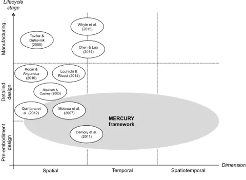
Figure 1 maps existing management frameworks from literature accord-ing to the type and the dimension of the entities to be managed, as well as the temporal position in the product life cycle. Such representation highlights a lack of spatiotemporal information (i.e. changes) management since most of the frameworks focus on the management of information in the spatial dimension and few of them in the temporal dimension. As a consequence, this figure introduces the MERCURY framework to manage spatial, tempo-ral and spatiotempotempo-ral information in the context of AOD so as to support product design and assembly planning reconciliation. This framework will be presented in more details in later sections of this paper.
3. Research background: Theory, ontology and approach
This section aims to introduce the foundation on which the proposed framework is based. It actually describes a theory built on a perdurantist philosophy and a dedicated multi-layer ontology (i.e. meta-, domain- and application-ontology) [? ].
3.1. JANUS as a spatiotemporal mereotopology-based theory
A mereotopological theory, called JANUS, has been introduced in [19], in order to formalise tacit knowledge covering product design and assem-bly process planning phases. The main objective of JANUS is therefore to qualitatively describe product evolution (i.e. in terms of changes over time) in the context of AOD based on a perdurantism philosophy. Perdurantism states that an object can evolve over time and space, since it is composed of different temporal parts through its existence. This theory is based on Smith’s spatial mereotopological primitives [42] and has been extended to the temporal and spatiotemporal dimensions. Smith’s primitives (such as Part of , Overlap or Tangent , etc.) are seen as useful to describe the physical relationships between two mechanical parts and are shown in Fig-ure 2 and Table 1. The temporal dimension is inspired from Allen’s proposal
Pre -e mb od ime nt de si gn MERCURY framework Demoly et al. (2011) Chen & Luo
(2014) Detailed de si gn
Spatial Temporal Spatiotemporal
Kocar & Akgunduz (2010) Lifecycle stage Dimension Whyte et al. (2015) Tavčar & Duhovnik (2005) Quintana et al. (2012) Motawa et al. (2007) Louhichi & Rivest (2014) Rouibah & Caskey (2003) Ma nu fa ct uri ng …
Figure 1: Map of existing management frameworks over lifecycle phases and dimensions
[1] and the previously developed spatial entities. So temporal primitives can associate two assembly operations and are presented in Table 1.
In addition to the spatial and temporal dimensions, a novel dimen-sion has been developed so as to describe objects evolution over space and time. The spatiotemporal dimension highlights two novel notions, called spatiotemporal regions (i.e. swept volume) and spatiotemporal primitives (i.e. classified into design changes, kinematic and technological pairs posi-tioning) [41, 47]. Here, design changes represent the intrinsic evolution of a product over time and kinematic pair positioning defines how a part is moving to be positioned in a specific manner with its physically connected parts. Mereotopological primitives have also been developed to enable the capture of design intents through the AOD process [40, 39]. Based on such a theory, the product evolution in the context of AOD can be described and fully understood by the product architect. Moreover, the JANUS theory has been built to also dynamically represent the product from design and assembly planning perspectives. As such, spatial (i.e. mechanical part) and temporal (i.e. assembly operation) objects can be related in the early design
stages via appropriate spatiotemporal relationships.
Figure 2: Smith’s spatial mereotopological primitives [42]
3.2. PRONOIA2 as a spatiotemporal ontology
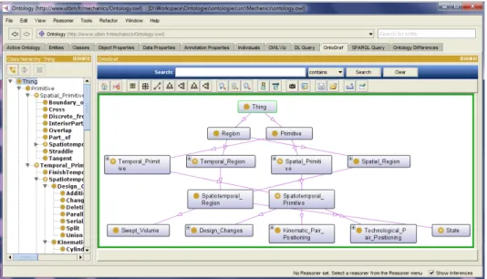
Based on JANUS mereotopological theory, PRONOIA2 ontology has been developed in order to be machine interpretable within PLM systems [18]. The objective is to solve the heterogeneity issue with semantics and logics so as to establish relationships among different dimensions and do-mains, as well as to ensure the management of information from PDM and MPM and CAD systems from a central place. PRONOIA2 is composed of a meta-, domain- and application-ontology. Figure 3 presents a part of the
ontological model. It has been developed using Prot´eg´e Editor and
Ontol-ogy Web Language 2 (OWL2) to describe classes and properties. Based on this knowledge structure, description logics (DL) and semantic web rule lan-guage (SWRL) rules have been set up with restrictions in order to facilitate semantic reasoning and consistency checking. Here information consistency
can be checked during the design process with HermiT reasoner in Prot´eg´e.
In addition, PRONOIA2 enables stakeholders (i.e. product architect, as-sembly planner and designer especially) to work collaboratively using the same semantics and makes the information exchange more effective [16]. This ontology aims to be integrated with PDM, MPM and CAD systems so as to ensure better information flows and then better data utilisation for decision making in AOD. As a result, existing heterogeneity gap can be minimised, since spatial and temporal information can now be reconciliated from a semantic and logical point of view. Last but not least, the ontology is expected to provide a better understanding [43] of the evolution of the product structure in the context of AOD.
T able 1: Spatial and temp oral mereotop ological primiti v es use d in JANUS [19] Definition Mereotop ological description Spatial x is part of y x P y := ∀ z (z O x → z P y ) x o v erlaps y x O y := ∃ z (z P x ∧ z P y ) x is discrete from y x D y := ¬ x O y x is In teriorP art of y x IP y := x P y ∧ ¬ x T y x crosses y x X y := ¬ x P y ∧ ¬ x D y x straddles y x St y := ∀ z (x IP z → z X y ) x is b oundary of y x B y := ∀ z (x P x → z St y ) x is tangen t of y x T y := ∃ z (z P x ∧ z B y ) Temp oral a is temp orally part of b bPt a := ∀ c( cOt b → cPt a ) a is start temp orall y part of b bPts a := ∃ c( bPt a ∧ cTt b ∧ c<a ) a is finish temp orally part of b bPtf a := ∃ c( bPt a ∧ bTt c ∧ a<c ) a is temp orally in terior part of b bIPt a := bPt a ∧ ¬ bPts a ∨ ¬ bPtf a a temp orally o v erlap s b bOt a := ∃ c( cPt b ∧ cPt a ) a temp orally precedes b a<b := ∃ c( a Tt c ∧ bPtf c) a is temp orally tangen t to b bTt a := ∃ c( cPts a ∧ cBt b) a is temp orally equal to b b= a := bIPt a ∧ a IPt b
Figure 3: Top-level vision of the PRONOIA2 ontology classes
3.3. PROMA as an integrated management approach
PROMA (PrOduct Relationships Management Approach) has been de-veloped to cover product relationships management issue in PLM [7] so as to increase their capabilities. In this approach, product-process information is reconciliated via a bill of relations (BOR), where part-to-part relationships are captured but not defined according to a spatiotemporal semantic. Such relationships can be related to assembly skeletons that are managed in a CAD BOM so as to support designers’ activities in CAD modelling stage. At this stage, no interface skeleton, such as introduced in JANUS theory, has been considered yet. Moreover, a MUVOA (MUlti-Views Oriented As-sembly) model [8] has been presented to highlight the link between product architect’s and assembly planner’s viewpoints in their related domains (i.e. respectively product design and assembly planning). It can be observed that an interface domain is not specified in this MUVOA model because of the lack of spatiotemporal information integration. The PROMA approach will be considered as a strong basis for the elaboration of the MERCURY framework in order to cover towards the spatiotemporal dimension, which enables considering product evolution in the context of AOD and changes in product design. By adding such a critical dimension, it will be needed and possible to (i) manage spatiotemporal information, (ii) keep traceability of
product-process information and (iii) reason at a logical and semantic level in order to ensure information consistency in product design and assembly planning phases.
3.4. Motivation
As stated in the above-mentioned sections, reconciliation between prod-uct design (covered by PDM systems and CAD applications) and assembly process planning (covered by MPM systems) information is widely consid-ered as a huge challenging issue. Indeed, such heterogeneous information needs to be managed with a seamless integration so as to cover spatial, tem-poral and spatiotemtem-poral issues. By considering spatiotemtem-poral description in PLM systems, the product evolution in terms of design changes and as-sembly will be captured and managed so as to increase awareness of involved actors in the AOD context. Built on this, needs have been highlighted to develop a spatiotemporal information management framework supporting product design and assembly planning reconciliation and enabling a consis-tent product description over space and time based on a previous elaborated theory and developed ontology (Step 3 of Figure 4). Such ambition repre-sents the last part and the outcome of a much larger research project, which aims to support the description and representation of object-process opera-tion relaopera-tionships over time and space within PLM systems.
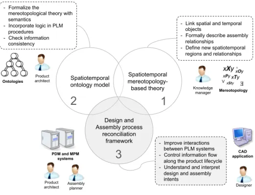
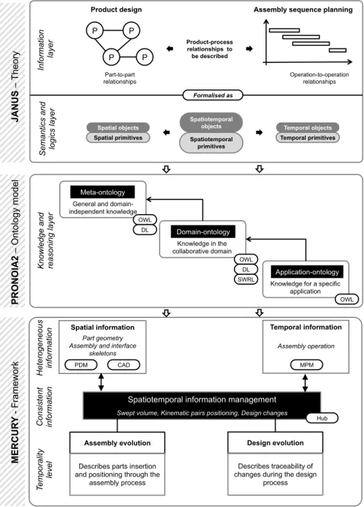
Built on these stakes, Figure 5 introduces the integration of a novel framework called MERCURY (ManagEment framework appRoaCh of prod-Uct and process Relationships in assemblY and design phases) within previ-ously developed PRONOIA2 ontology and JANUS theory. The objective of the theory is to qualitatively describe product-process relationships so as to support product evolution in the context of AOD [19]. Such mereotopolog-ical formalisation has enabled the development of a multi-layer ontology in order to tackle heterogeneous issues in assembly oriented design [18]. Here the theory and the related ontology provides a semantic and logical foun-dation to associate spatial and temporal information so as to reconciliate PDM and MPM systems in an efficient manner. By bridging these two in-formation systems, product design and evolution over time can be managed so as to enhance dynamic aspect in product design. The main objective of MERCURY is to introduce a novel information management layer (i.e. spatiotemporal layer) in the design process in order to manage assembly and design changes that a product undergoes. With such a framework, a better articulation between product design and assembly planning is enabled. As a result, the MERCURY framework aims to (i) reconciliate heterogeneous information in the spatial and temporal dimensions in the beginning of the
Spatiotemporal ontology model Spatiotemporal mereotopology-based theory Design and Assembly process reconciliation framework
- Link spatial and temporal objects
- Formally describe assembly relationships
- Define new spatiotemporal regions and relationships
- Improve interactions between PLM systems - Control information flow
along the product lifecycle - Understand and interpret
design and assembly intents
- Formalize the
mereotopological theory with semantics - Incorporate logic in PLM procedures - Check information consistency Designer Knowledge manager Product architect Ontologies CAD application
2
Mereotopology3
Assembly planner PDM and MPM systems1
Product architectFigure 4: Overall vision of the research
embodiment design stage, (ii) manage and control the reconciliation from PDM and MPM systems and (iii) integrate the reconciliated information within CAD applications.
4. Spatiotemporal information management framework
The proposed spatiotemporal information management framework (MER-CURY) can be applied on two different applications: (i) the management of assembly evolution in the context of AOD and (ii) the management of changes during the design process. In the first application, assembly evo-lution mainly concerns the product move during the assembly process (e.g. kinematic and technological pairs positioning). On the other hand, the sec-ond application is focused on design evolution by describing design changes during the design process.
JA N U S – T he ory
General and domain-independent knowledge
Knowledge in the collaborative domain
Knowledge for a specific application Meta-ontology Domain-ontology Application-ontology OWL SWRL DL OWL DL OWL P P P P Part-to-part relationships Operation-to-operation relationships Product-process relationships to be described In fo rma tio n la ye r Se ma nt ics and lo gi cs la ye r Spatial objects Spatial primitives Temporal objects Temporal primitives Spatiotemporal objects Spatiotemporal primitives Formalised as PR O N O IA 2 – Ontology mo de l Kn ow le dg e and re aso ni ng la ye r
Product design Assembly sequence planning
MER C U R Y - F ra me w ork Het ero ge ne ou s in fo rma tio n
Spatiotemporal information management
Swept volume, Kinematic pairs positioning, Design changes
Assembly evolution Design evolution
PDM MPM
Hub CAD
Describes parts insertion and positioning through the
assembly process
Describes traceability of changes during the design
process C on si st en t in fo rma tio n Te mp ora lit y le ve l Spatial information Part geometry Assembly and interface
skeletons
Temporal information
Assembly operation
4.1. Management of product-process information consistency
In the context of AOD, two dimensions can be considered since product design relates to the spatial (e.g. mechanical part) dimension and assembly process planning to the temporal (e.g. assembly operation) one. Indeed in current engineering activities, the product architect mainly deals with spatial objects while the assembly planner works with temporal objects. Here the main objective is to associate spatial and temporal objects via spatiotemporal objects (i.e. swept volumes) and relationships such as previ-ously described in JANUS theory (see Figure 6). The management of such spatiotemporal relationships will ensure a better interaction, coordination of product-process information [3] and information flow consistency. This will lead to the consideration of changes and a consistent product definition over space and time.
Spatial
objects Spatiotemporal objects Temporal objects
Part
Part
Operation Relation
Figure 6: Association between spatial and temporal objects through spatiotemporal rela-tionships
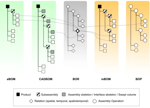
From another perspective, the fact of associating spatial and temporal objects is seen as a critical step towards the reconciliation of data struc-tures in PDM-MPM systems and CAD application. Figure 7 shows the introduction of the bill of relations (BOR) in order to capture and manage part-to-part relationships over time from a central place. This means that the set of information flows can be orchestrated from this specific structure, and all related structures (i.e. eBOM, CADBOM, mBOM and BOP) can be managed in a consistent and bidirectional manner. PDM systems usually manage data structures within the eBOM and related product configura-tions, while MPM systems work with mBOM and BOP (bill of processes)
to define assembly sequences and process plans. The idea is then to in-corporate spatiotemporal relationships within a BOR in the embodiment design stage, so as to bridge the gap of information heterogeneity between product design and assembly process planning. Here, spatiotemporal rela-tionships are defined as novel technical objects, which link part-to-part re-lationships (including spatial primitives and spatial objects) with assembly operations (temporal objects) so as to generate swept volumes (spatiotem-poral objects). Spatiotem(spatiotem-poral relationship is vital to describe part-to-part relationships over time and also design changes during the product design process. This novel primitive (e.g. RevoluteOP ) can be directly associated to a part-to-part relation (e.g. revolute pair) within an assembly oriented context. Actually, the revolute pair only describes the final state of the kinematic pair between two physical parts, while RevoluteOP represents all states when two discrete parts are moving to be positioned in a revolute manner.
Product Subassembly Assembly skeleton / Interface skeleton / Swept volume Assembly Operation
eBOM CADBOM BOR mBOM BOP
Relation (spatial, temporal, spatiotemporal)
Figure 7: Introduction of the BOR as a reconciliation structure between PDM, MPM and CAD systems
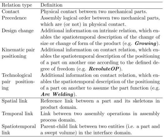
parts and assembly operations in order to increase efficiency in product de-sign. The spatiotemporal relationships therefore give a great understanding of how parts are being connected in a dynamic way [3]. A relationship is here considered as the means to establish, represent or maintain a consistent link between two technical entities [9]. This one also gives information about product evolution, rationalises design intents, captures changes carried out over space and time and ensures the consistency of product-process defini-tion [51]. In our context, mereotopological primitives and their ontological implementation enable the introduction of a spatiotemporal layer within PLM systems, by capturing five kinds of relationships and three kinds of association links as described below (the first two relations are reused from [9]) in Table 2.
Table 2: List of the relation types used in MERCURY
Relation type Definition
Contact Physical contact between two mechanical parts.
Precedence Assembly logical order between two mechanical parts,
which are (or not) in physical contact.
Design change Additional information on intrinsic relation, which
en-ables the spatiotemporal description of the change of size or change of form of the product (e.g. Growing ). Kinematic pair
positioning
Additional information on contact relation, which en-ables the spatiotemporal description of the positioning of a part on another one according to the defined de-gree of freedom (e.g. RevoluteOP ).
Technological
pair
position-ing
Additional information on contact relation, which en-ables the spatiotemporal description of the positioning of a part on another to assume the part function (e.g. Arc Welding ).
Spatial link Reference link between a part and its skeletons in
product domain.
Temporal link Link between two assembly operations in assembly
process domain. Spatiotemporal
link
Parent-child link between two entities (i.e. a part and a swept volume) in the interface domain.
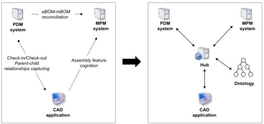
Figure 8 shows an emergent shift in information systems implementa-tion. Actually, current implemented PLM systems in industry are generally
related to each other in pairs in order to exchange information [5]. It should be noted that system-to-system connections works in a non-reciprocal man-ner (e.g. PDM to MPM and CAD to MPM in Figure 8) and therefore provide weak interoperability capacity [32]. Here the management of het-erogeneous information highlights the need of a seamless connection between information systems [32]. As a consequence, a hub-and-spokes architecture is proposed so as to ensure the orchestration of information flows and solve interoperability issues (right part of the Figure 8). The hub aims at intro-ducing a top-management level to manage new technical objects and their inferred relationships (especially in the spatiotemporal dimension), and en-suring a better coordination of the PLM systems in the architectural design stage. The final objective is to enhance a continuity of product descrip-tion/definition over space and time by introducing a novel spatiotemporal management framework. Hub CAD application PDM system MPM system Ontology CAD application MPM system PDM system Assembly feature cognition Check-in/Check-out Parent-child relationships capturing eBOM-mBOM reconciliation
Figure 8: Shift in PLM systems implementation from current industrial usage to a hub-and-spokes architecture
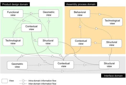
The AOD philosophy requires the association and integration of spe-cific viewpoints related to product design and assembly process planning domains. As such, the proposed efforts are based on the MUVOA model [9], which aims to separate and link concerns of both domains. Built on this, Figure 9 presents the relationships (intra-domain and inter-domain) between the views (e.g. structural, functional, contextual and so on) in the product design and assembly process domain, and also between both domains via a novel domain, the interface domain (related to the
spatiotem-poral dimension). In this specific domain, three views have been introduced (namely contextual, structural and geometric views) in order to describe the BOR, swept volumes and spatiotemporal relationships to name a few. For instance, this framework proposes to link the contextual view of the product domain and the contextual view in the assembly process domain through an added contextual view in the interface domain so as to promote information flow continuity in AOD. Table 3 shows the different views within their do-mains and the involved stakeholders. It should be noted that a novel actor has been introduced in order to cover the interface domain, the mediator. An example of technical objects for each view is also introduced.
Functional view
Structural view Geometric
view Behavioral view
Contextual view Technological view Structural view Contextual view Technological view
View Intra-domain information flow
Structural view Contextual view Geometric view
Product design domain Assembly process domain
Interface domain Inter-domain information flow
Figure 9: Adapted MUVOA model linking product design and assembly process domains through the interface domain
4.2. Information flow through PLM
This section introduces the information flow through PLM systems. In Figure 10, the hub is linked to PRONOIA2 ontology with a double arrow, which ensures the interoperability between systems by providing semantics among PDM, MPM and CAD systems. Semantics provides a common vo-cabulary between stakeholders involved in a project and gives via ontology
T able 3: Link b et w ee n stak e holders and views in pro duct and assem bly pro cess Domain View Sta k eholder T ec hnical ob ject Pro duct F unctional Pro duct arc hitect T ec hnic a l function T ec hnological Pro duct arc hitect & Designer T ec hnological pair Structural Pro duct arc hitect Pro duct config uration, eBOM Geometric Designer Assem bly constrain t, part geometry Con textual Assem bly planner & Pro duct arc hitect Kinematic pair, con tact relation Assem bly Structural Assem bly planner mBOM and BOP pro c ess Con textual Assem bly planner Precedence constrain ts and pro duction con text Beha vioural Assem bly planner Assem bly sequence and pro cess plan T ec hnological Assem bly planner T ec hnological pairs and assem bly tec hnologies In terfa c e Structural Mediator BOR Geometric Mediator Assem bly and in terface sk eleton, S w ept v olume Con textual Mediator Kinematic & tec hnological pa ir p ositioning & Design cha nge (e.g. Union, Gro wing and Deformation)
a support to knowledge management. Besides, double arrows are present at each link in order to ensure seamless data changes at any time and informa-tion flow in a bidirecinforma-tional manner. As such, bridges enable the importainforma-tion and exportation of information from one information system to another. The hub is therefore considered as the dashboard, which controls informa-tion flow between engineering and manufacturing.
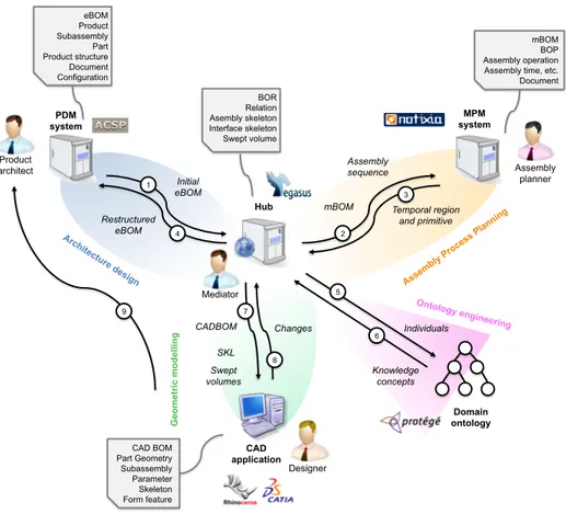
The entities, which are defined and managed within PLM systems (i.e. PDM and MPM systems) and CAD application, are also presented in Fig-ure 10. Dotted arrows represent information as data input the hub, and full arrows are dedicated to information generated from information sys-tems and applications. The PDM system exports the eBOM defined by the product architect and receives the restructured eBOM based on the gener-ated assembly sequence. The MPM system receives the mBOM after that the assembly sequence has been defined by ASDA algorithm and exports the temporal regions and primitives. As for CAD application receives the CAD BOM and sends back the geometric information (such as geometric skeletons), as well as the changes made by the designer along the design process. All steps of Figure 10 are described in the upcoming paragraphs.
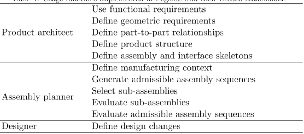
The hub – called Pegasus [7] – has been developed with Rhapsody soft-ware, which uses graphical models to generate software applications. Rhap-sody facilitates collaboration and supports information tracking [23]. This modelling environment based on UML (Unified Modelling Language) has been used to assist stakeholders in managing information through visualisa-tion. The proposed hub is a web-based system and a mediator application between information systems (i.e. PDM and MPM) and CAD tools in AOD [7]. Its role is to manage product relationships and control information (with spatial, temporal and spatiotemporal dimensions) flow between information systems and ontology with internal regulation procedures, so as to bridge the heterogeneity gap between engineering and manufacturing. Moreover, Pegasus provides a decision-making support for sub-assemblies (SA) selec-tion and assembly operaselec-tion structures generaselec-tion by capturing design for assembly (DFA) rules. So Pegasus’ purpose is to bring concurrent engineer-ing benefits into the product design and assembly sequence plannengineer-ing stages. This hub has been improved in order to consider the new functionalities and new entities to be managed. Table 4 specifies the eleven functions imple-mented in Pegasus and the associated stakeholders. Here the MERCURY framework starts at the architectural design phase, by considering as data input defined functions and preliminary solutions. The proposed framework ensures the orchestration of information flows, reasoning capacity and then product-process reconciliation from a central place. The different steps of
PDM system MPM system CAD application Domain ontology Initial eBOM Restructured eBOM Temporal region and primitive Assembly sequence Knowledge concepts Individuals CADBOM Changes Hub Mediator Product architect Assembly planner Designer Ontology engineering G eo m etr ic modelling mBOM SKL Swept volumes 1 4 2 3 5 6 7 8 9 eBOM Product Subassembly Part Product structure Document Configuration BOR Relation Asembly skeleton Interface skeleton Swept volume mBOM BOP Assembly operation Assembly time, etc. Document CAD BOM Part Geometry Subassembly Parameter Skeleton Form feature
Figure 10: Main orchestration and reconciliation mechanisms within MERCURY and Pegasus
MERCURY framework can be deployed as follows:
Step 1 The product architect defines the eBOM in the PDM system. Then, Pegasus is automatically and directly populated with the spatial infor-mation from PDM. Spatial inforinfor-mation corresponds to spatial region (e.g. part). The product architect also provides the part-to-part re-lationships within a graph (e.g. precedence, contact, kinematic pairs and technological pairs) in Pegasus. Spatiotemporal regions (i.e. parts which are going to move to be positioned in their final state) and kine-matic pairs positioning are then computed from this aforementioned information.
Step 2 Based on the part-to-part relationships, the ASDA algorithm com-putes several admissible assembly sequences, on which the assembly planner will select the most appropriate one. Built on this, the mBOM is automatically exported to the MPM system, where assembly oper-ations are defined from a technological perspective. As for the assem-bly sequence, operation-to-operation relationships are refined by using Precedence and temporal primitives.
Step 3 Manufacturing relational information is then sent to Pegasus. Step 4 The eBOM, built on the assembly sequence and its related
sub-assembly levels, is updated to the PDM system.
Step 5 All engineering and manufacturing data are sent to PRONOIA2 ontology so as to populate the application-ontology layer. Spatial, temporal and spatiotemporal information is automatically sorted out in the conceptual model (i.e. PRONOIA2 ontology), which is the top layer of the proposed framework.
Step 6 Then Pegasus synchronises the information from PDM and MPM systems through the PRONOIA2 ontology. Here the BOR is generated based on the previoulsy generated kinematic pairs positioning. Step 7 The spatiotemporal graph of assembly evolution is generated from
the eBOM, mBOM, swept volumes, kinematic pairs and temporal
primitives within Pegasus. This enable the definition of assembly,
interface skeletons as well as the CAD BOM and the simplified swept volumes in the CAD application. By considering this AOD context, the designer can build parts’ geometry.
Step 8 Based on the assembly skeleton structure, the designer can allocate volume, shape and values related to each skeleton. The relational ge-ometric information is then sent to Pegasus, which will capture the design and assembly intents. In addition, the designer has the op-portunity to undertake changes, which are managed by automatically updating the BOR. Swept volumes or changed parts are dynamically represented and designers can directly see the impacts of changes. If other changes are required, then new information is again updated. Changes are captured in the spatiotemporal graph of design evolu-tion, computed from changes listed by the designer along the design process. Changes can be visualised and dynamically carried out.
Table 4: Usage functions implemented in Pegasus and their related stakeholders
Product architect
Use functional requirements Define geometric requirements Define part-to-part relationships Define product structure
Define assembly and interface skeletons
Assembly planner
Define manufacturing context
Generate admissible assembly sequences Select sub-assemblies
Evaluate sub-assemblies
Evaluate admissible assembly sequences
Designer Define design changes
Step 9 Once designer has defined all product geometric characteristics, the CAD models can be stored by using check-in/check-out procedures in the PDM system.
If a part is missing or the designer wants to change something, then he can restart the whole procedure in order to visualise new results. Moreover, the Pegasus application has been updated by integrating a domain-ontology and an application-ontology and representation means. Pegasus plays now a role of a semantic Web-service. An API (Application Programming Inter-face) has been created to extract relevant information from PDM and MPM systems and automaticall transfer it into the data model of Pegasus (devel-oped with Rhapsody IBM software). Since the application-ontology does not use the same IT language as PLM systems and as they do not deal with the same information, the information needs to be converted with developed plug-in to be accessible to PRONOIA2 ontology. The inference reasoner (here HermiT 1.3.7) of the ontology processes checking procedure and en-sures the consistency of the model. The ontology also enables structuring information and bringing semantics and logics in PLM systems. Pegasus and PRONOIA2 ontology (i.e. conceptual model) ensure interoperability and consistency between information systems and applications covering en-gineering and manufacturing departements with real-time information flow. Figure 11 presents how ontological information is integrated into informa-tion systems and applicainforma-tion. Indeed, PRONOIA2 ontology is composed of six relevant parts (such as temporal primitives, spatial primitives, spa-tiotemporal primitives, spatial region, temporal region and spaspa-tiotemporal
region), such as represented in Figure 3. Here, spatial regions are defined in the PDM system, temporal regions in the MPM system and remaining information within the hub and PRONOIA2 ontology.
Figure 11: Ontological information integrated into PDM and MPM systems and the hub application
Moreover, Table 5 introduces the novel functionalities and the associated mereotopological concepts (such as proposed in [19]) embedded in Pegasus. In this table, the novel information is described in the second row, the input/output information (i.e. information imported from one system and exported to PRONOIA2 ontology through the hub) in the third row and the information tracking is shown in the last row. It should be noticed that the JANUS mereotopological theory has been entirely used within the hub so as to carry out its functionalities.
Figure 12 and Figure 13 have been introduced so as to describe MER-CURY framework procedures about assembly and design evolutions. The proposed flowcharts present mechanisms (i.e. grey boxes) and related in-put/output information (i.e. white boxes). These mechanisms match the steps 1, 6, 7 and 8 of Figure 10. Figure 12 and Figure 13 focus on the as-sembly evolution application and design evolution application respectively. Here, the paper contributes to the generation of a BOR bridging spatial and temporal information, a CAD BOM, swept volumes and two spatiotempo-ral graphs. More precisely, the BOR links PDM and MPM heterogeneous information with dedicated relationships, introduced in the JANUS theory [19], such as kinematic pairs positioning and design changes. As such, Pega-sus behaves like a mediator. Besides, the assembly and interface skeletons
T able 5: F unctionalities and mereotop ological concepts of the h ub F unctionali tie s Mereotop ological concepts Information Definition of c on tact relationship Spatial primitiv e Definition of prece dence relationship T emp oral primitiv e Definition of kinematic pair Spatial primitiv e Creation of kinematic pair p ositioning Spatiotemp oral primitiv e Definition of te chnological pair Spatiotemp oral primitiv e Definition of des ign changes relationship Spatiotemp oral primitiv e Definition of te mp oral pri m iti v e T emp oral primitiv e Creation of sw ept v olume Spatiotemp oral region Input\ Output information Imp ort and exp ort of eBOM Spatial region Imp ort and exp ort of spatiotemp oral primitiv e Spatiotemp oral primitiv e Imp ort and exp ort of assem bly op eration T emp oral re gion Information traceability Represen tation of part-to-part relationships graph Spatial region, temp oral and spatiotemp oral primitiv es Represen tation of purely spatial graph S patial region and spatiotemp oral primitiv e Represen tation of the BOR Spatial, tem p oral and spatiotemp oral regions and spa-tiotemp oral primitiv e Represen tation of assem bly e v olution graph Spatial, temp oral and spatiotemp oral regions, and temp oral and spatiotemp oral primitiv es Represen tation of change definition graph Spatial and temp oral regions, and temp oral and spa-tiotemp oral primitiv es Represen tation of design ev olution graph Spatial, temp oral and spatiotemp oral regions, and temp oral and spatiotemp oral primitiv es
are defined in the JANUS theory with the description of spatiotemporal relationships. In addition, the related swept volumes provides a better un-derstanding about how parts are being assembled at the early design stages. This also brings awareness to designer on how parts move during the as-sembly. At the end of Step 7, if the designer does not need to modify the product, the flowchart is over, otherwise the designer can keep on with step 8.
At the step 7 of the framework, a novel graph (such as introduced in [19]) has been introduced to support product evolution in the context of AOD based on assembly planning. Leonardo Da Vinci [11] states that “a picture is worth a thousand words”. Actually, designers will be more aware of changes with a graph, which can visually explain an idea by outlining parts and rela-tionships between them. The emergence process has already been followed in order to succeed to develop representations to designers. This leads to knowledge acquisition [17]. This graph is required, as current CAD trees do not introduce temporal and spatiotemporal information. They just show the history of the model building at the final design phase. As such they deal with static and purely spatial information. Although, this information is not enough to understand why the product is the way it is at the end of the design process. The spatiotemporal graph gives to product architect and designer the opportunity to have an overall view of the product assem-bly evolution by representing milestones in collaborative project. Indeed it federates, represents and links spatial and temporal information. With such a graph, stakeholders can understand how entities are linked over space and time, and how they interact. As such, the information propagation through design and manufacturing structures is managed. Table 6 introduces the link between the new views of the MUVOA model (see Figure 9) and the MERCURY framework. This table highlights the reasons why the MUVOA model has been improved.
To sum up, MERCURY has been inspired by the musical domain. An orchestra is for instance composed of wind (here PDM system) and brass (here MPM system) instruments. The orchestra is guided by the conductor (here the hub), which gives the rhythm. Each family of instruments (here information systems) includes musicians (here agents). Each musician will make his own sound (here link between the information systems and hub), which will be heard by the conductor. All sounds, coming from wind and brass instruments, create a sheet music (here the ontology is instantiated). If music is created by all instruments family, then it is a full symphony.
START
Define kinematic pairs and precedence relationships
END
Kinematic pairs
Convert into kinematic pairs positioning
Precedence constraints
Kinematic pairs
positioning primitives Temporal Spatiotemporal regions Compute spatiotemporal
regions
Generate the BOR
Generate the spatiotemporal graph for assembly evolution
Assembly evolution graph
Generate design space in CAD application
BOR
Design space
Figure 12: Flowchart of the proposed framework to manage “assembly evolution” within Pegasus hub
No START
Define design changes
END Design changes
Manage dynamic changes
Update the BOR
Represent swept volumes and dynamic in CAD
Dynamic CAD model Other change required? Generate spatiotemporal graph of design evolution
Spatiotemporal graph of design
evolution
Yes
Figure 13: Flowchart of the proposed framework to manage “design evolution” within Pegasus hub
Table 6: Link between new product-process views of the MUVOA model and the MER-CURY framework
View Related step
number
Reason for this improvement
Geometric 1 Need of managing new entities describing
evolutions during the assembly and design process
Contextual 7 and 8 Need of new tools enabling describing
prod-uct evolution during the assembly process so as to keep tracking of product architect’s in-tents, as well as need of new tools enabling changes description so as to keep a track of designer’s intents
Structural 6 Need of a new structure for design
infor-mation based on relationships, as new spa-tiotemporal entities are used and required to be integrated
4.3. Representation of design and assembly evolutions within a CAD appli-cation
Current CAD tools (e.g. Catia V5) can only design static spatial product[2] and represent the final state of the physical model [13]. They are considered as endurant software, which is currently their major drawback [25]. In real world, products are dynamically evolving over space and time. As such,
Rhinoceros software1 (i.e. perdurant software) with its Grasshopper2
plug-in, which are open-source, has been exploited, so as to instantaneously visu-alize assembly and design evolutions of products. This visual programming tool can generate geometry with interactive modification [6]. The overall objective of using Grasshopper is for the designer to control all evolutions that the product could encounter during the early product development pro-cess. By doing so, JANUS mereotopological theory has been implemented within a CAD tool (Rhinoceros) and via dedicated algorithmic procedures (similar to building blocks) developed within Grasshopper (see example in
1https://www.rhino3d.com/en
2
Figure 14).
Figure 14: Dynamic representation of Decrease relationship within Rhinoceros and Grasshopper
Figure 14 presents an example of design evolution, namely the Decrease relationship. This product has been first designed in Catia V5 and then
transferred to Rhinoceros. Here, the red part needs to be rescaled and
decreased because of the designers experience. The designer just uses the developed boxes in Grasshopper (e.g. Decrease box) and links it to the changing parts in Rhinoceros (e.g. link with the Shaft). The designer dy-namically and separately changes the x,y,z dimensions of the parts. Here, the parts have been decreased of 60% in the x dimension, 50% in the y
dimension and 80% in the z dimension. After choosing the right length and width, a smaller product is obtained, controlled by the red box for the shaft and the blue box for the bearing. The smaller product has been moved to the right side of the figure so as to have a better visualization. Here the shaft and the bearing have been linked through scaling parameters. As such, the relationships between these two parts is ensured over time even when the product undergoes changes. Figure 15 represents the swept volume (i.e. in red) of the bearing, resulting from the RevoluteOP primitive. A box named “swept volume” has been developed with Grasshopper in order to visualize the move of the part on the product. As such, swept volume is automatically created after defining the start and end interface (based on interface skeletons previously described in JANUS theory), as well as the directed curve of the move (based on the assembly skeletons). With such a representation, designer can dynamically see parts’ moves (from a starting interface to the final position in the product assembly) and the space needed during the assembly process.
Figure 16 presents the creation of the swept volume of the CylindricalOP from step 1 to step 4. The different pictures below explain the main steps of the swept volume creation within CAD tools. For the simplified swept volume generation, interface skeleton is extended. On the contrary here in step 4, Part 5 is extended to generate Swept volume 5. The figure also compares the reasoning of the theory (from left to right on the chronological order) and within CAD tools (from right to left). Some similarities appear between the description of the theory and the one of the CAD tool. In both descriptions, skeletons are used to generate the swept volume. In CAD tool, the final state of the assembly with its skeleton is considered and the path of the part, as well as its swept volume afterwards. In the JANUS theory, discrete parts are considered and the swept volume is created when a part is moving to get to its position in the assembly. In future works, all kine-matic pairs, technological pairs and design changes should be represented with Grasshopper. The main advantage of this plug-in is that the change, defined at the step 8 of the framework (cf. Figure 10), is instantaneously represented and the designer can dynamically play with it. As such, de-sign process is no more static and can now be considered as dynamic with product design evolution over time.
Figure 15: Dynamic representation of the swept volume resulting from the Revolute relationship within Rhinoceros and Grasshopper
5. Case study in a drones-based application
5.1. Case study: Drones-based design for medical emergency
The case study is solved by following the different steps of the proposed framework (cf. Figure 10). The objective of this case study is to design a medical drone. Medical drone is mainly used to reduce the delay between the
Figure 16: Comparison between JANUS theory and CAD application reasoning on assem-bly evolution
alert time and the intervention time. This time can actually be crucial for heart attacks, research of victims and so on. First, functional analysis has been carried out in order to understand the needs and find some preliminary solutions (cf. Table 7). After defining the requirements, some pre-concepts have been drawn. Based on morphogenesis, one solution is illustrated in Figure 17. Here, the case study has been simplified and only described a part of the whole assembly. The case study border has been marked out in Figure 17 with a black circle.
Table 7: Functions and related solutions for the case study
Functions Solutions
Fly in order to bring medical equipment Four drive turbines
Land on every kind of grounds Landing gear with three legs
Go anywhere Retractable rear arms
Studied sub-assembly in the case study
Figure 17: Representation of a pre-concept using morphogenesis
5.2. MERCURY deployment regarding assembly evolution
Define eBOM The eBOM is composed of ten parts, represented in ACSP PDM system on Figure 18 and by circles on Figure 19.
Define kinematic pairs and precedence relationships The part-to-part relationships are defined in a directed graph (cf. Figure 19) by the
Figure 1 8: eBOM defined in A CSP as PDM system
product architect representing the contextual view of the proposed
model. In this graph, the contact (i.e. link between two circles),
precedence relationships (i.e. arrow) and kinematic pairs between two parts can be visualised. At the same time, a purely spatial graph is created in the right side of Figure 19. This graph represents the final state of the assembly process. With such a graph, stakeholders can know for instance if a part is at the core of the assembly. The green indicator means that steps have already been done, orange indicator means “work in progress” and red means that works need to be done later.
Figure 19: Contextual view of Pegasus hub
Deduce spatiotemporal regions and convert kinematic pairs positioning Each spatiotemporal region is deduced from the part-to-part relation-ships graph. In fact, spatiotemporal regions are presented as the parts touching the end of the arrow in Figure 19. Here the swept volumes (i.e. spatiotemporal regions) are Swept volume 2, Swept volume 4, Swept volume 7, Swept volume 9, Swept volume 10, Swept volume SA1, Swept volume SA3 and Swept volume SA4. Kinematic pairs position-ing are also directly generated from the defined kinematic pairs. For in-stance, Revolute pair is converted into RevoluteOP with the JANUS theory. The parts and skeletons are listed in Table 8, where k and f are respectively the assembly and interface skeletons. In brackets,
Table 8: Parts list of the case study No Part name 1 Drone leg 2 Piston rod 3 Pneumatic cylinder 4 Spring 5 Frame
6 Rack and pinion 7 Rack and pinion motor
8 Cog
9 Propeller support 10 Propeller
Table 9: Assembly skeletons and interface skeletons list of the case study
No Assembly skeleton No Interface skeleton k1 Line (4-2) f1 Surface (4-2)
k2 Point (2-1) f2 Surface (2-1)
k3 Plane (7-6) f3 Surface (7-6)
k4 Plane (SA3-SA2) f4 Surface (SA3-SA2)
k5 Line (SA4-5) f5 Surface (SA4-5)
k6 Line (10-9) f6 Surface (10-9)
k7 Plane (10-9) f8 Surface (9-8)
k8 Line (9-8) f9 Surface (SA1-5)
k9 Line (SA1-5) f10 Surface (4-3)
k10 Plane (4-3)
both parts and sub-assemblies linked with the skeleton are mentioned. These skeletons depends on the chosen spatiotemporal relationships and their related mereotopological description.
Generate assembly sequence Based on part-to-part relationships, the ASDA algorithm generates a relevant assembly sequence, which can be expressed as:
Assembly = [SA1 ; 5 ; SA4 ]
Assembly = [[1 ; 2 ; 3 ; 4 ] ; 5 ; [SA3 ; SA2 ; 10 ]] Assembly = [[1 ; 2 ; 3 ; 4 ] ; 5 ; [[8 ; 9 ] ; [6 ; 7 ] ; 10 ]]
(denoted SA1 ), which represents the landing system. Besides, the spa-tial regions 6 and 7 are embedded in a Sub-Assembly (denoted SA2 ) to represent the rack and pinion system and the spatial regions 8 and 9 are embedded in a Sub-Assembly (denoted SA3 ) for the arm sys-tem. Finally, the spatial regions SA3, SA2 and 10 are embedded in a Sub-Assembly (denoted SA4 ). The assembly sequence is exported to MPM and then refined by the assembly planner. Operations are defined from the assembly sequence. Here, the different assembly
op-erations are expressed within Notixia3 MPM system (cf. Figure 20).
The restructured eBOM (cf. Figure 21) considers the parts, as well as the sub-assemblies previously detected.
Figure 20: Representation of the assembly sequence planning within MPM system (i.e. Notixia)
For this case study, the third level of PRONOIA 2 has been auto-matically populated with previous information. The individuals are
shown in Figure 22 and are linked together with properties. This
figure is composed of nine states represented in the middle. The
dif-3
Figure 21: Restructured eBOM of the case study within PDM system (i.e. ASCP)
ferent states allow visualising what happens in the context of AOD and show the product evolution over space and time. After populat-ing the ontology, designers can check that the application-ontology is composed of all concepts needed in the description of product-process evolution through AOD as well as their consistency. The ontology in its current shape proposes some available queries to designers so as to look for information requests in a collaborative assembly design environment. In addition, the reasoner can query the ontology and give designers suggestions on how parts will be assembled over time. So it could also provide some design recommendations to support de-signers. After having added information into PRONOIA2, designers have a suitable design context based on perdurantist vision to define consistent mechanical assembly.
Figure 22: Instances of the on tology with the “kinematic pairs p ositi oning” primitiv es for the case study
eBOM, BOP, swept volumes and kinematic pairs positioning.
Generate the spatiotemporal graph If the instantiated information in PRONOIA2 ontology is consistent, the “assembly evolution” spatiotem-poral graph can be generated. All information is gathered to describe product evolution, horizontally read from left to right (cf. Figure 23). Hence, spatial (i.e. mechanical part), temporal (i.e. assembly opera-tion) and spatiotemporal (i.e. swept volume in the context of AOD) re-gions are represented and linked with primitives. Only rere-gions, which undergo a change at a specific assembly operation OPi, are presented at OPi in order to facilitate understanding of the reader. Here, changes are considered when novel spatiotemporal relationships appear. As such, the product architect and designer can understand what hap-pens for each operation, especially where a part is situated and linked regarding to others, and which part is moving. In that case, the de-signer knows which part is evolving (and becomes a swept volume) and which part remains static. In fact, the designer can follow how each object is evolving over time and what are the changes that the product undergoes in the context of AOD. For instance, he can read, through the spatiotemporal graph of the hub application, that at OP30, Swept volume 2 is moving to be positioned in a SphericalOP manner on Part 1. Then this representation, embedded in Pegasus hub, provides an overview of the product evolution along its assembly sequence to the product architect and designer before starting the product mod-elling phase in CAD. This representation therefore introduces a novel working support to the product architect and designer by giving them an overview of product-process evolution. Table 10 compares current CAD information and our proposed graph. Current CAD tools do not capture temporal (i.e. assembly sequence) and spatiotemporal infor-mation (i.e. spatial evolution of the product over time). Therefore, some information is missing in actual CAD tools.
Generate skeletons, simplified swept volumes, and CAD BOM Assembly and interface skeletons are generated based on the selected kinematic
pairs positioning. For each spatiotemporal relationship, related
skele-tons have been defined in JANUS theory. The different skeletons
are represented in Figure 24. Here the future CAD BOM has been rethought. The CAD BOM includes spatiotemporal information. From these relationships, specific skeletons (denoted SKL) and swept vol-umes (denoted SV) are created. This information has been included